EP1482765A2 - Baking method for heating an object (an inner pipe, an outer pipe) - Google Patents
Baking method for heating an object (an inner pipe, an outer pipe) Download PDFInfo
- Publication number
- EP1482765A2 EP1482765A2 EP04291314A EP04291314A EP1482765A2 EP 1482765 A2 EP1482765 A2 EP 1482765A2 EP 04291314 A EP04291314 A EP 04291314A EP 04291314 A EP04291314 A EP 04291314A EP 1482765 A2 EP1482765 A2 EP 1482765A2
- Authority
- EP
- European Patent Office
- Prior art keywords
- baking
- pipe
- heating
- heat
- baking method
- Prior art date
- Legal status (The legal status is an assumption and is not a legal conclusion. Google has not performed a legal analysis and makes no representation as to the accuracy of the status listed.)
- Withdrawn
Links
Images

Classifications
-
- H—ELECTRICITY
- H05—ELECTRIC TECHNIQUES NOT OTHERWISE PROVIDED FOR
- H05B—ELECTRIC HEATING; ELECTRIC LIGHT SOURCES NOT OTHERWISE PROVIDED FOR; CIRCUIT ARRANGEMENTS FOR ELECTRIC LIGHT SOURCES, IN GENERAL
- H05B3/00—Ohmic-resistance heating
- H05B3/40—Heating elements having the shape of rods or tubes
- H05B3/42—Heating elements having the shape of rods or tubes non-flexible
-
- F—MECHANICAL ENGINEERING; LIGHTING; HEATING; WEAPONS; BLASTING
- F16—ENGINEERING ELEMENTS AND UNITS; GENERAL MEASURES FOR PRODUCING AND MAINTAINING EFFECTIVE FUNCTIONING OF MACHINES OR INSTALLATIONS; THERMAL INSULATION IN GENERAL
- F16L—PIPES; JOINTS OR FITTINGS FOR PIPES; SUPPORTS FOR PIPES, CABLES OR PROTECTIVE TUBING; MEANS FOR THERMAL INSULATION IN GENERAL
- F16L59/00—Thermal insulation in general
- F16L59/06—Arrangements using an air layer or vacuum
-
- F—MECHANICAL ENGINEERING; LIGHTING; HEATING; WEAPONS; BLASTING
- F16—ENGINEERING ELEMENTS AND UNITS; GENERAL MEASURES FOR PRODUCING AND MAINTAINING EFFECTIVE FUNCTIONING OF MACHINES OR INSTALLATIONS; THERMAL INSULATION IN GENERAL
- F16L—PIPES; JOINTS OR FITTINGS FOR PIPES; SUPPORTS FOR PIPES, CABLES OR PROTECTIVE TUBING; MEANS FOR THERMAL INSULATION IN GENERAL
- F16L59/00—Thermal insulation in general
- F16L59/06—Arrangements using an air layer or vacuum
- F16L59/065—Arrangements using an air layer or vacuum using vacuum
-
- H—ELECTRICITY
- H05—ELECTRIC TECHNIQUES NOT OTHERWISE PROVIDED FOR
- H05B—ELECTRIC HEATING; ELECTRIC LIGHT SOURCES NOT OTHERWISE PROVIDED FOR; CIRCUIT ARRANGEMENTS FOR ELECTRIC LIGHT SOURCES, IN GENERAL
- H05B3/00—Ohmic-resistance heating
- H05B3/40—Heating elements having the shape of rods or tubes
- H05B3/54—Heating elements having the shape of rods or tubes flexible
- H05B3/58—Heating hoses; Heating collars
Definitions
- the present invention relates to a baking method for heating an object to remove gas molecules occluded in the object. More specifically, the present invention relates to a baking method most suitable for baking a superconducting cable, various pipes such as a cold water pipe, a feed water pipe, an LNG pipe, a refrigerant pipe, a hot water pipe, a hot water supply line, and a heating medium pipe, pipe fittings, and a heat insulation pipe or a heat insulation vessel used as a piping instrument.
- various pipes such as a cold water pipe, a feed water pipe, an LNG pipe, a refrigerant pipe, a hot water pipe, a hot water supply line, and a heating medium pipe, pipe fittings, and a heat insulation pipe or a heat insulation vessel used as a piping instrument.
- heat processing For production of a vacuum double heat insulation pipe having a vacuum layer formed between an inner pipe and an outer pipe, for example, heat processing called baking to heat the heat insulation pipe is performed to remove gas molecules occluded in a material of the heat insulation pipe to enhance a degree of vacuum.
- heat processing called baking to heat the heat insulation pipe is performed to remove gas molecules occluded in a material of the heat insulation pipe to enhance a degree of vacuum.
- heat processing called baking to heat the heat insulation pipe is performed to remove gas molecules occluded in a material of the heat insulation pipe to enhance a degree of vacuum.
- heat processing for the baking, roughly two methods are known.
- One method is heating an object by arranging heating means such as a heater near the heat insulation pipe (for example, see Japanese Patent Laying-Open No. 9-296779 and No. 11-125609).
- the other method is introducing heated gas into the vacuum layer of the heat insulation pipe and then exhausting the gas (for example, see Japanese Patent Laying-Open No. 9-273659).
- a baking object is heated from the outside of the vacuum layer mainly with conductive heat from the heater.
- a member of the baking object which faces the vacuum layer cannot be heated directly, and energy is highly lost from a heat source.
- the member facing the vacuum layer can be heated more efficiently by arranging the heater inside the vacuum layer, it is not practical because the heater and a wiring thereof release gas that decreases a degree of vacuum and, in addition, it complicates the configuration to remove the wiring from the vacuum layer to an atmospheric side.
- a baking device becomes so large and complicated that a space for setting the device is limited.
- a baking device becomes larger by installation of the heater, which limits a place for setting.
- the larger the surface area of the member facing the vacuum layer is, the larger the heater and a power supply thereof become, and the wiring of the heater will also be complicated.
- the heating means such as a heater, a size of the baking object that can be heated is then limited.
- portions of the baking device located near the heater are also heated, extra portions other than the baking object are also heated to high temperature (such as 70 °C or higher). Therefore, as prescribed heat resistance is also needed for the elements used in the heated portions, selection of the elements is limited.
- a required amount of gas increases in proportion to a baking time.
- Nitrogen gas or the like is used as the heated gas, and thus a cylinder to feed the gas and heating means for the gas are included in the baking device. For a longer baking time, the amount of gas needed increases, and thus a large cylinder is required which leads to upsizing of the device. In addition, as the object is indirectly heated with the heated gas, the heating is not energy-efficient.
- the heated gas is usually introduced from one end side of the heat insulation pipe and exhausted from the other end side.
- temperatures of the heated gas are different at the inlet and outlet of the gas, it is difficult to uniformly heat the baking object.
- the vacuum layer is large and long, the effect is conspicuous and the object is hardly baked to uniform temperature.
- the heated gas cannot be fed again once evacuation is started after the heating of the object with introduced heated gas, even when a temperature in the vacuum layer decreases. Therefore, effect of the baking cannot be exerted efficiently.
- an object of the present invention is to provide a baking method which enables energy-efficient heating.
- Another object of the present invention is to provide a baking method which enables uniform heating of a long or large object.
- the present invention achieves the foregoing objects by making a baking object itself a heat production element.
- a baking method of the present invention is a baking method for heating an object having a vacuum layer formed therein to remove gas molecules occluded in the object, characterized in that the object itself is made to be a heat production element for heating.
- a baking object itself a heat production element
- the object can directly be heated, which enhances energy efficiency of heating.
- configuration of a baking device can be simplified as additional heating means such as a heater or gas is not required.
- a vacuum double heat insulation pipe is generally formed with an inner pipe and an outer pipe made of metal, and is conductive. When the object as such is energized, the object itself can easily produce heat.
- the members are electrically insulated from each other and each member is separately energized.
- the plurality of members are made of different materials or have different shapes or sizes, and may have values of resistance different from each other.
- attained temperatures or times to reach to the attained temperatures may differ with the same amount of passed current, which results in uneven heating.
- separate energization for each member enables substantially uniform heat production as the whole object.
- the members are electrically insulated from each other.
- Means for the insulation is not limited.
- the baking object is a vacuum double heat insulation pipe having inner and outer pipes, for example, the inner and outer pipes can be electrically insulated from each other with an insulation flange located between the pipes.
- the insulation flange is mounted so as to block opening ends of the inner and outer pipes, and a commercially available product can be utilized as the flange.
- the baking method of the present invention can be applied to baking of a vacuum heat insulation structure.
- the method is most suitable for baking, for example, a superconducting cable, various pipes such as a cold water pipe, a feed water pipe, an LNG pipe, a refrigerant pipe, a hot water pipe, a hot water supply line, and a heating medium pipe, pipe fittings, and a heat insulation pipe or a heat insulation vessel used as a piping instrument.
- a baking method of the present invention is described, in which a baking object is a vacuum double heat insulation pipe for a superconducting cable.
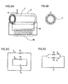
- the heat insulation pipe has an inner pipe 1 and an outer pipe 2 arranged coaxially and spaced apart from each other. Though these inner and outer pipes 1, 2 may be straight tubes, corrugated metal pipes are used in this embodiment in consideration of bendability.
- opening ends of two pipes 1, 2 are sealed with an annular conductive flange 3 to bring pipes 1, 2 into conduction, and a vacuum layer is formed between inner and outer pipes 1, 2.
- a radiant heat reflector (not shown) such as Super Insulation (trade name) is usually accommodated.
- the vacuum layer is formed by evacuation from an exhaust port 4 projectingly mounted on outer pipe 2. Electrodes are then mounted on both end portions of the heat insulation pipe, and an energization device 5 is connected via a lead.
- FIG. 1C shows an equivalent circuit of the baking device.
- a calorific value per unit length of the heat insulation pipe can be expressed as RI 0 2 (W/m), where R ( ⁇ /m) represents resistance per unit length, V (V) represents a voltage of the energization device, and I 0 (A) represents a total current, and a calorific value of the whole length can be controlled uniformly by controlling current value I 0 .
- the calorific value per unit length can be considered as substantially even.
- wall surfaces of inner and outer pipes facing the vacuum layer can be heated concurrently and substantially uniformly.
- conduction and convection of heat within the vacuum layer are substantially ignorable when an insulation layer has a high degree of vacuum, small amount of heat escapes from a surface of the inner pipe to the periphery when the inner pipe is heated, and a temperature of the inner pipe can be controlled economically with small amount of passed current.
- heating of inner and outer pipes may become uneven when the inner and outer pipes have significantly different values of resistance.
- inner pipe 1 and outer pipe 2 are insulated from each other and each of pipes 1, 2 is independently energized to enable uniform heating.
- a heat insulation pipe used in this embodiment is similar to that in the first embodiment.
- an insulation flange 6 is used as a flange to seal end portions of two pipes.
- the insulation flange is an annular flange formed with inner and outer edge portions of metal and a middle portion of insulation material. Shapes and materials of insulation flange 6 are not limited, provided that the flange has a function of insulating pipes 1, 2.
- an insulation flange manufactured by Cosmotec co., ltd can be applied, which is commercially available as a vacuum airtight component.
- the inner and outer pipes electrically insulated with insulation flange 6 are then respectively connected to independent energization devices 5A and 5B.
- uniform baking of the whole heat insulation pipe is enabled by controlling currents of energization devices 5A, 5B so as to provide uniform temperatures of inner and outer pipes 1, 2.
Landscapes
- Engineering & Computer Science (AREA)
- General Engineering & Computer Science (AREA)
- Mechanical Engineering (AREA)
- Thermal Insulation (AREA)
- Resistance Heating (AREA)
- Superconductors And Manufacturing Methods Therefor (AREA)
- Pipe Accessories (AREA)
- Muffle Furnaces And Rotary Kilns (AREA)
Abstract
Description
Claims (5)
- A baking method for heating an object (1, 2) having a vacuum layer formed therein to remove gas molecules occluded in said object (1, 2); characterized in that
said object (1, 2) itself is made to be a heat production element for heating. - The baking method according to claim 1, characterized in that
said object (1, 2) is made of conductive metal and said object (1, 2) is energized for heat production. - The baking method according to claim 2, characterized in that
said object (1, 2) is formed with a plurality of members, and
the members are electrically insulated from each other and each member is independently energized so that the object produces heat substantially uniformly. - The baking method according to claim 3, characterized in that
the plurality of members forming said object (1, 2) are an inner pipe (1) and an outer pipe (2), and
the inner pipe (1) and outer pipe (2) are electrically insulated from each other with an insulation flange located between the pipes. - The baking method according to claim 2, characterized in that
said object (1, 2) is a heat insulation pipe of a superconducting cable.
Applications Claiming Priority (2)
| Application Number | Priority Date | Filing Date | Title |
|---|---|---|---|
| JP2003148420A JP4528495B2 (en) | 2003-05-26 | 2003-05-26 | Baking method of heat insulation pipe for superconducting cable |
| JP2003148420 | 2003-05-26 |
Publications (2)
| Publication Number | Publication Date |
|---|---|
| EP1482765A2 true EP1482765A2 (en) | 2004-12-01 |
| EP1482765A3 EP1482765A3 (en) | 2007-03-28 |
Family
ID=33128207
Family Applications (1)
| Application Number | Title | Priority Date | Filing Date |
|---|---|---|---|
| EP04291314A Withdrawn EP1482765A3 (en) | 2003-05-26 | 2004-05-25 | Baking method for heating an object (an inner pipe, an outer pipe) |
Country Status (5)
| Country | Link |
|---|---|
| US (1) | US7002116B2 (en) |
| EP (1) | EP1482765A3 (en) |
| JP (1) | JP4528495B2 (en) |
| KR (1) | KR100824227B1 (en) |
| CN (1) | CN100379318C (en) |
Cited By (1)
| Publication number | Priority date | Publication date | Assignee | Title |
|---|---|---|---|---|
| CN108851244A (en) * | 2018-07-24 | 2018-11-23 | 深圳麦克韦尔股份有限公司 | Toast the heating component of smoking set and vacuum heat-insulation |
Families Citing this family (10)
| Publication number | Priority date | Publication date | Assignee | Title |
|---|---|---|---|---|
| JP4565385B2 (en) * | 2004-12-01 | 2010-10-20 | 住友電気工業株式会社 | Vacuum insulation tube |
| JP4730520B2 (en) * | 2005-04-20 | 2011-07-20 | 住友電気工業株式会社 | Baking method |
| JP4919402B2 (en) * | 2006-08-31 | 2012-04-18 | Necトーキン株式会社 | Piping heater |
| KR100820359B1 (en) * | 2006-10-31 | 2008-04-07 | 주식회사 디엠에스 | Lamp firing device |
| JP5168367B2 (en) * | 2011-01-21 | 2013-03-21 | 住友電気工業株式会社 | Long body |
| JP2016192858A (en) * | 2015-03-31 | 2016-11-10 | 昭和電線ケーブルシステム株式会社 | Cryogenic cable system and baking method of cryogenic cable system |
| CN106556618B (en) * | 2016-10-20 | 2019-06-28 | 中国空间技术研究院 | A kind of vacuum bakeout test method of spacecraft cable system |
| CN108072171A (en) * | 2016-11-16 | 2018-05-25 | 北京北方华创微电子装备有限公司 | The heating unit and semiconductor processing equipment of gas piping |
| CN109595430B (en) * | 2019-01-09 | 2024-04-30 | 上海电缆研究所有限公司 | A take out mouthful device for vacuum sleeve |
| CN115978924A (en) * | 2022-12-19 | 2023-04-18 | 江苏天合储能有限公司 | Pole heating vacuum baking device and baking method thereof |
Family Cites Families (17)
| Publication number | Priority date | Publication date | Assignee | Title |
|---|---|---|---|---|
| JPS5167515A (en) * | 1974-12-10 | 1976-06-11 | Furukawa Electric Co Ltd | DANNETSUKANRO |
| JPS5442124U (en) * | 1977-08-31 | 1979-03-22 | ||
| JPS58140987A (en) * | 1982-02-15 | 1983-08-20 | 東レ株式会社 | Composite carbon heater |
| EP0082678B1 (en) * | 1981-12-18 | 1987-08-26 | Toray Industries, Inc. | Improved electric resistance heating element and electric resistance heating furnace using the same as heat source |
| JPS5925936B2 (en) * | 1981-12-18 | 1984-06-22 | 東レ株式会社 | heating furnace |
| JPS60113892A (en) * | 1983-11-18 | 1985-06-20 | 日立電線株式会社 | Vacuum evacuating method of refrigerant transport pipe |
| JPS62141391A (en) * | 1985-12-17 | 1987-06-24 | 日本鋼管株式会社 | Method of heat-insulating double pipe type heaing pipeline |
| IT1205085B (en) * | 1987-06-24 | 1989-03-10 | Getters Spa | VACUUM INSULATED ELECTRIC SUPERCONDUCTOR WITH THE USE OF A GETTER DEVICE |
| JPH01150096A (en) * | 1987-12-04 | 1989-06-13 | Hitachi Metals Ltd | Conduit having heat-insulating function |
| JP2520050Y2 (en) * | 1991-11-21 | 1996-12-11 | 日本鋼管工事株式会社 | Composite rubber packing for water stop device |
| JPH05198353A (en) * | 1992-01-22 | 1993-08-06 | Sanko Kogyo Kk | Heating device for gas passage forming equipment |
| CH688328A5 (en) * | 1993-07-12 | 1997-07-31 | Sgl Carbon Ag | Electrical heating. |
| JPH09273659A (en) * | 1996-04-03 | 1997-10-21 | Hitachi Ltd | Vacuum equipment baking equipment |
| JPH09296779A (en) * | 1996-05-07 | 1997-11-18 | Nippon Sanso Kk | Vacuum evacuation method and apparatus |
| JPH103825A (en) * | 1996-06-12 | 1998-01-06 | Toshiba Corp | Superconducting bus line |
| US5791377A (en) * | 1996-07-08 | 1998-08-11 | Yazaki Corporation | Electrically heated conduit |
| JPH11125609A (en) * | 1997-10-23 | 1999-05-11 | Tosei Electro Beam Kk | Method for testing baking of vacuum double pipe |
-
2003
- 2003-05-26 JP JP2003148420A patent/JP4528495B2/en not_active Expired - Fee Related
-
2004
- 2004-05-24 KR KR1020040036811A patent/KR100824227B1/en not_active Expired - Fee Related
- 2004-05-25 EP EP04291314A patent/EP1482765A3/en not_active Withdrawn
- 2004-05-25 CN CNB2004100459273A patent/CN100379318C/en not_active Expired - Fee Related
- 2004-05-25 US US10/852,163 patent/US7002116B2/en not_active Expired - Fee Related
Cited By (1)
| Publication number | Priority date | Publication date | Assignee | Title |
|---|---|---|---|---|
| CN108851244A (en) * | 2018-07-24 | 2018-11-23 | 深圳麦克韦尔股份有限公司 | Toast the heating component of smoking set and vacuum heat-insulation |
Also Published As
| Publication number | Publication date |
|---|---|
| CN1573200A (en) | 2005-02-02 |
| JP2004353681A (en) | 2004-12-16 |
| JP4528495B2 (en) | 2010-08-18 |
| US20040238528A1 (en) | 2004-12-02 |
| US7002116B2 (en) | 2006-02-21 |
| CN100379318C (en) | 2008-04-02 |
| KR20040101918A (en) | 2004-12-03 |
| HK1069429A1 (en) | 2005-05-20 |
| EP1482765A3 (en) | 2007-03-28 |
| KR100824227B1 (en) | 2008-04-24 |
Similar Documents
| Publication | Publication Date | Title |
|---|---|---|
| US7002116B2 (en) | Baking method | |
| KR101360878B1 (en) | Modular Heater Systems | |
| CN117051383A (en) | Heating furnaces and semiconductor equipment | |
| JP4584722B2 (en) | Plasma processing apparatus and semiconductor device manufactured by the same | |
| EP1707858A1 (en) | Vacuum heat insulation valve | |
| US20250003065A1 (en) | Method and apparatus for gas and vapor deposition precursor delivery heater | |
| US20140097176A1 (en) | Heater assembly | |
| JP2022546917A (en) | electric heater | |
| CN207910216U (en) | A kind of cooling device for power cable fusion splice stranded conductor | |
| KR20000047882A (en) | An electric continuous flow heater and a method for its manufacture | |
| JPH11108283A (en) | Heated piping and semiconductor manufacturing equipment | |
| CN116437507A (en) | A kind of heating equipment, semiconductor coating equipment and heating method | |
| CN117894658A (en) | Plasma etching equipment, dielectric window heating device and system | |
| JP4822893B2 (en) | Wiring structure of heater for vacuum pump device | |
| CN206602675U (en) | A kind of heater wire of flat conductor structure | |
| CN209759571U (en) | Evaporation source heating electric lead-in device and vacuum evaporation coating equipment | |
| JP5331582B2 (en) | Heating device with cooling function | |
| KR101959266B1 (en) | Fixing jig apparatus for discharge line of the semiconductor manufacturing equipment | |
| JPH02192592A (en) | Vacuum heat treatment furnace | |
| CN114622078B (en) | Heat treatment method for long tubular workpiece | |
| EP3506763A1 (en) | Improved electrical energy transfer system for a wire mesh heater | |
| JP2976337B1 (en) | Defrost equipment | |
| JPH0235292A (en) | Composite tube for transporting fluid | |
| CN206963096U (en) | A kind of temp auto-controlled heating tape with temperature control element | |
| CN105658035A (en) | Special-shaped heat-conducting cable with installation fins |
Legal Events
| Date | Code | Title | Description |
|---|---|---|---|
| PUAI | Public reference made under article 153(3) epc to a published international application that has entered the european phase |
Free format text: ORIGINAL CODE: 0009012 |
|
| AK | Designated contracting states |
Kind code of ref document: A2 Designated state(s): AT BE BG CH CY CZ DE DK EE ES FI FR GB GR HU IE IT LI LU MC NL PL PT RO SE SI SK TR |
|
| AX | Request for extension of the european patent |
Extension state: AL HR LT LV MK |
|
| PUAL | Search report despatched |
Free format text: ORIGINAL CODE: 0009013 |
|
| AK | Designated contracting states |
Kind code of ref document: A3 Designated state(s): AT BE BG CH CY CZ DE DK EE ES FI FR GB GR HU IE IT LI LU MC NL PL PT RO SE SI SK TR |
|
| AX | Request for extension of the european patent |
Extension state: AL HR LT LV MK |
|
| RIC1 | Information provided on ipc code assigned before grant |
Ipc: H05B 3/42 20060101ALI20070219BHEP Ipc: H05B 3/58 20060101AFI20041001BHEP |
|
| 17P | Request for examination filed |
Effective date: 20070405 |
|
| AKX | Designation fees paid |
Designated state(s): DE FR GB IT |
|
| 17Q | First examination report despatched |
Effective date: 20080709 |
|
| RAP1 | Party data changed (applicant data changed or rights of an application transferred) |
Owner name: SUMITOMO ELECTRIC INDUSTRIES, LTD. |
|
| STAA | Information on the status of an ep patent application or granted ep patent |
Free format text: STATUS: THE APPLICATION HAS BEEN WITHDRAWN |
|
| 18W | Application withdrawn |
Effective date: 20120326 |