EP1482445A2 - Image interpolation apparatus and method - Google Patents
Image interpolation apparatus and method Download PDFInfo
- Publication number
- EP1482445A2 EP1482445A2 EP20040101746 EP04101746A EP1482445A2 EP 1482445 A2 EP1482445 A2 EP 1482445A2 EP 20040101746 EP20040101746 EP 20040101746 EP 04101746 A EP04101746 A EP 04101746A EP 1482445 A2 EP1482445 A2 EP 1482445A2
- Authority
- EP
- European Patent Office
- Prior art keywords
- image signals
- interpolation
- input image
- given number
- input
- Prior art date
- Legal status (The legal status is an assumption and is not a legal conclusion. Google has not performed a legal analysis and makes no representation as to the accuracy of the status listed.)
- Withdrawn
Links
Images


Classifications
-
- G—PHYSICS
- G06—COMPUTING; CALCULATING OR COUNTING
- G06T—IMAGE DATA PROCESSING OR GENERATION, IN GENERAL
- G06T3/00—Geometric image transformation in the plane of the image
- G06T3/40—Scaling the whole image or part thereof
- G06T3/4023—Decimation- or insertion-based scaling, e.g. pixel or line decimation
-
- B—PERFORMING OPERATIONS; TRANSPORTING
- B60—VEHICLES IN GENERAL
- B60N—SEATS SPECIALLY ADAPTED FOR VEHICLES; VEHICLE PASSENGER ACCOMMODATION NOT OTHERWISE PROVIDED FOR
- B60N2/00—Seats specially adapted for vehicles; Arrangement or mounting of seats in vehicles
- B60N2/80—Head-rests
- B60N2/894—Head-rests with rods solidly attached to the back-rest
-
- B—PERFORMING OPERATIONS; TRANSPORTING
- B60—VEHICLES IN GENERAL
- B60N—SEATS SPECIALLY ADAPTED FOR VEHICLES; VEHICLE PASSENGER ACCOMMODATION NOT OTHERWISE PROVIDED FOR
- B60N2/00—Seats specially adapted for vehicles; Arrangement or mounting of seats in vehicles
- B60N2/80—Head-rests
- B60N2002/899—Head-rests characterised by structural or mechanical details not otherwise provided for
Abstract
Description
- The present invention relates to an image interpolation apparatus comprising a digital interpolation filter means.
- It is often necessary to change the resolution of an image signal, for instance to match the pixels available in a display device, such as a liquid crystal display panel. When the resolution has to be increased, linear interpolation is used in the vertical and/or the horizontal directions.
- US-A-6281873 discloses a method for performing vertical scaling and filtering with the aid of a single processor by using a poly-phase filter.
- Hereinbelow, the term, "image interpolation apparatus" means an apparatus for increasing the resolution of an image signal by increasing the number of pixels using an interpolation method. Such image interpolation apparatuses can be found in image display apparatuses. Other names for such apparatuses include scaler, format transform apparatus and image up-scaling apparatus.
- Examples of interpolation methods include bi-linear interpolation and cubic convolution interpolation. The bi-linear interpolation and cubic convolution interpolation methods use finite impulse response (FIR) filters.
- The bi-linear interpolation method interpolates an input signal using a 2-tap filter with the characteristic shown in Figure 1A. In this method only the two immediately on either side of the location of the new pixel are used.
- The cubic convolution interpolation interpolates an input signal using a 4-tap filter with the characteristic shown in Figure 1B. In this method two pixels on either side of the location of the new pixel are used.
- However, neither of these methods is optimal for all signals. For example, if the cubic convolution interpolation method is used, high frequency regions of the image are degraded.
- Specifically, when pixels P1 to P8, sampled as shown in Figure 2A, are interpolated using cubic convolution interpolation, it can be seen that pixels interpolated in section II are relatively dim compared to sections I and III as shown in Figure 2B. Accordingly, in this case, it is desirable to use another interpolation in section II, which produces less degradation.
- An image interpolation apparatus, according to the present invention, is characterised by control means for changing the transfer function of filter means in dependence on a frequency-related parameter of the image signal being interpolated.
- The control means may be configured to determine whether the pattern of brightness of pixels in a moving window meets a predetermined criterion or predetermined criteria and change the transfer function of the filter means (350) in dependence on the result of said determination. The length of the moving window is preferably not shorter than the largest number of taps employed in said filter means. The criterion or criteria may comprise the presense of a run of three inter-pixel periods during which the brightness changes by an amount greater than a predetermined negative number or a run of three inter-pixel periods during which the brightness changes by an amount less than a predetermined positive number. The predetermined negative and positive numbers have magnitudes that are small compared with the maximum magnitude that the image signal pixel brightness may have so as to provide a degree of noise immunity. The criterion or criteria comprise a plurality of instances of no change in brightness over an inter-pixel period.
- The filter means may comprises an FIR filter with variable coefficients which can be changed by the control means to change the transfer function of the filter means. Alternatively, separate filters may be used. Preferably, there is a memory for storing a plurality of sets of coefficients, each set corresponding to a different filter tranfer function, e.g. a 4-tap filter transfer function and an 8-tap filter transfer function.
- Further preferred and optional features of the present invention are set forth in claims 11 to 25 appended hereto.
- An embodiment of the present invention will now be described, by way of example, with reference to Figures 3 to 8 of the accompanying drawings, in which:
- Figures 1A and 1B illustrate the characteristics of 2-tap and 4-tap filters used in conventional interpolation methods;
- Figures 2A and 2B illustrate a problem that arises in the use of cubic convolution interpolation;
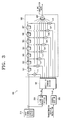
- Figure 3 is a block diagram of an image interpolation apparatus according to the present invention;
- Figure 4 shows eight sequentially input image signals to illustrate the generation of a filter selection signal;
- Figure 5 illustrates the case in which the filtering selection section of the apparatus in Figure 3 determines whether the eight input image signals belong to a graphic region or an edge region;
- Figures 6A and 6B illustrate interpolation positions calculated, according to a resolution transformation ratio, in the control section shown in Figure 3;
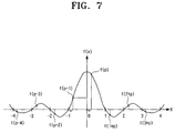
- Figure 7 illustrates a method of producing interpolation coefficients with the aid of given interpolation positions calculated in the control section shown in Figure 3; and
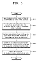
- Figure 8 is a flowchart illustrating an image interpolation method performed by the image interpolation apparatus shown in Figure 3.
-
- Referring to Figure 3, an
image interpolation apparatus 300 according to the present invention comprises an imagesignal storage section 310, afiltering selection section 320, acontrol section 330, acoefficient storage section 340 and aninterpolation filter 350. - The
image interpolation apparatus 300 is an apparatus for up-scaling, i.e. increasing the resolution of, input image signals of a first resolution to output image signals of a second resolution according to a predetermined resolution transformation ratio. The resolution transformation ratio is the ratio of the input and output image signal resolutions. - The image
signal storage section 310 stores image signals input from an image signal source. The imagesignal storage section 310 provides the input image signals for thefiltering selection section 320 and theinterpolation filter 350 under the control of thecontrol section 320 to be described later. - The
filtering selection section 320 analyzes changes in the brightness of the input image signals provided from from the imagesignal storage section 310. Thefiltering selection section 320 outputs a filtering selection signal for controlling the selection of one filter from a plurality of different filters on the basis of the analysis of the signal brightness. Specifically, thefiltering selection section 320 determines the frequency of the input image signals and outputs an appropriate filtering selection signal. - In the present embodiment, a 4-tap filter using cubic convolution interpolation and an 8-tap filter using poly-phase interpolation used by way of example. The 4-tap filter is used for low frequency image signals, i.e. those having a frequency lower than a reference frequency, and the 8-tap filter is used for image signals having a frequency higher than the reference frequency.
- More specifically, the
filtering selection section 320 determines whether there exists a pattern in which the brightness of the input image signal continuously increases or decreases over a previously established time for a given number of pixels. If it is determined that such a pattern exists, thefiltering selection section 320 determines it to be a low frequency region and outputs a filtering selection signal for selecting the 4-tap filter. Whereas, if it is determined that such a pattern does not exist, thefiltering selection section 320 outputs a filtering selection signal for selecting the 8-tap filter. - If the brightness does not change by more than a reference value between two successive input pixels, the
filtering selection section 320 determines that the previously determined pattern, (i.e. increasing or decreasing) is continuing. The use of the reference value is to prevent an edge region from being determined to be a high frequency region by recognizing the edge as image signals interleaved with a noise signal. - When the brightness comparison for the given number of input pixels is completed, the oldest pixel is cleared from the given number of pixels and a new pixel input into the
filtering selection section 320. Thus, thefiltering selection section 320 operates on a pixels in a moving window. - In the present example, the moving window is eight pixels wide and the filtering selection signal is generated by analysing the brightness of eight input pixels and determining whether there exists a pattern where the brightness continuously increases or decreases across four pixels, i.e. three inter-pixel periods.
- In Figure 4, the first to the eighth input pixels, x(n) to x(n+7) in the moving window, are expressed in terms of brightness. In addition, the numbers below the first to eighth input image signals x(n) to x(n+7) are the corresponding brightness levels.
- Referring to Figure 4(a), it can be seen that the brightness decreases over the first three inter-pixel periods, i.e. from the first input pixel x(n) to the fourth input pixel x(n+3), while the brightness increases over the next three inter-pixel periods from the fourth input pixel x(n+3) to the seventh input pixel x(n+6). In this case, the
filtering selection section 320 outputs the 4-tap filter selection signal. - The
filtering selection section 320 calculates the differences in brightness between pair of successive pixels and if the brightness decreases, a brightness change value is set to '1', while if the brightness levels increase, a brightness change value is set to '0' instead. Thefiltering selection section 320 determines whether the brightnesses form an increase pattern or a decrease pattern, from the brightness change values. For example, in Figure 4(a), the brightness decreases between the first input image signal x(n) and the second input image signal x(n+1), and the brightness change value is set to '0'. Whereas, the brightness increases between the fourth input image signal x(n+3) and the fifth input image signal x(n+4) and the brightness change value is set to '1'. In this example, there is consequently a run of three "0"s followed by a run of three "1"s. Therefore, thefiltering selection section 320 outputs a selection signal for the 4-tap filtering during these runs. - Referring to Figure 4(b), it can be seen that the brightness of the sixth to eighth input pixels is the same. Because the brightness increased between the fifth input pixel x(n+4) and the sixth pixel x(n+5), the
filtering selection section 320 treats the sixth to eighth pixels as part of a sequence of increasing brightness. Therefore, thefiltering selection section 320 determines that the brightness has an increasing pattern from the fifth to eighth input pixels x(n+4) to x(n+7) over three consecutive inter-pixel periods and, thus, thefiltering selection section 320 outputs the 4-tap filtering selection signal. - Referring to Figure 4(c), it can be seen that there is no interval in which the brightness continuously increases or decreases over three consecutive inter-pixel periods between the first and eighth input pixels x(n) to x(n+7). In this case, the
filtering selection section 320 outputs the 8-tap filtering selection signal. - Referring to Figure 4(d), the brightness decreases between the first input pixel x(n) and the second input pixel x(n+1), whereas the brightness increases between the second input pixel x(n+1) and the third input pixel x(n+2). However, because the difference between the brightness of the second input pixel x(n) and the second input pixel x(n+1) is lower than a previously established reference level, e.g. 5, the
filtering selection section 320 treat the actual increase between the second and third pixels as a continuation of a decreasing pattern. This is identically applied to the brightness levels between the third input image signal x(n+2) and the fourth input image signal x(n+4). In the case shown in Figure 4d, thefiltering selection section 320 determines that the brightness levels form a decrease pattern, of which the brightness levels continuously decrease over three consecutive times and thus thefiltering selection section 320 outputs the 4-tap filtering selection signal. - In addition, the
filtering selection section 320 can detect graphic regions and edge regions. If the pixel brightness does not change over a plurality of pixels a plurality of times, thefiltering selection section 320 that the pixels belong to a graphic region or an edge region and outputs the 4-tap filtering selection signal because because a ringing phenomenon occurs if the 8-tap filter is used on graphic or edge regions. - For example, when the brightnesses of the first to eighth input pixels x(n) to x(n+7) are as shown in Figure 5, there exist three sections (indicated by dotted lines), in each of which two consecutive input pixels have equal brightnesses. Therefore, the
filtering selection section 320 determines that pixels belong to a graphic region or an edge region and thus thefiltering selection section 320 outputs the 4-tap filtering signal. In Figure 5, the numbers below the first to eighth input image signals x(n) to x(n+7) are the brightnesses of the respective pixels. - The
control section 330 controls the input rate of the input image pixels from the imagesignal storage section 310 into theinterpolation filter 350 according to the resolution transformation ratio. This is the case in which the present invention relates to image up-scaling, or an increase in resolution. In the case of image down-scaling, or a decrease in resolution, thecontrol section 330 controls the output rate of the output image pixels from theinterpolation filter 350. In addition, thecontrol section 330 calculates an interpolation position for each of the given number of input image pixels input into thefiltering selection section 320 according to the resolution transformation ratio. - Figures 6A and 6b are drawings for illustrating interpolation positions calculated according to a predetermined resolution transformation ratio in the control section shown in Figure 3.
- Referring to Figure 6A, the white circles indicate positions of input image signals and the black circles indicate interpolation positions calculated according to a resolution transformation ratio.
- Specifically, if the transformation ratio is 1:2 as shown in Figure 6A, the scale factor in the horizontal direction is 0.5. Therefore, if horizontal interpolation is executed by using 8-tap poly-phase interpolation kernel as shown in Figure 6B, it can be seen that the interpolation positions for the input pixels correspond to -3.5, -2.5, -1.5, - 0.5, +0.5, +2.5 and +3.5, respectively. As another example, if the resolution transformation ratio is 3:5, the scale factor in the horizontal direction is 0.6.
- The
coefficient storage section 340 stores interpolation coefficients corresponding to a plurality of interpolation positions, that is, tap weight values, in which the interpolation coefficients of tap weight values are classified by the filters. The interpolation coefficients can be calculated by using the 8-tap poly-phase interpolation kernel as shown in Figure 7. - Figure 7 illustrates a method for producing coefficients on the basis of the predetermined interpolation positions calculated in the control section of Figure 3.
- Referring to Figure 7, in the 8-tap poly-phase interpolation kernel, eight input pixels participate in interpolation. In addition, when a plurality of interpolation positions are (p-4), (p-3), (p-2), (p-1), (p), (p+1), (p+2) and (p+3), a plurality of interpolation coefficients needed for obtaining final interpolation data are f(p-4), f(p-3), f(p-2), f(p-1), f(p), f(p+1), f(p+2) and f(p+3). Here, p is a relative positional value in each tap interval.
- These interpolation coefficients are previously calculated using the 8-tap poly-phase interpolation kernel and stored in the
coefficient storage section 340. For example, if each interval between taps is divided into 32 sections, interpolation positions in an interval between taps will have relative positional values such as 0, 1/32, 2/32,3/32, ... , 31/32, 1, respectively, and vertical and horizontal interpolation coefficients corresponding to respective interpolation positions are calculated in advance and stored in thecoefficient storage section 340. Meanwhile, each interval between taps is capable of being divided into another number of sections, such as 16 sections, 64 sections, etc. - The
coefficient storage section 340 stores horizontal interpolation coefficients for 4-tap filtering and 8-tap filtering. Therefore, thecoefficient storage section 340 outputs horizontal interpolation coefficients corresponding to the filtering selection signal output from thefiltering selection section 320 and to a given number of interpolation positions calculated from thecontrol section 330. - That is, when the 8-tap filtering is selected by the
filtering selection section 320, thecoefficient storage section 340 outputs eight interpolation coefficients. Whereas, if the 4-tap filtering is selected by thefiltering selection section 320, thecoefficient storage section 340 outputs eight interpolation coefficients, in which 2 taps at each end of the 8-taps have an interpolation coefficient of '0'. This is because theinterpolation 350 to be described later is provided with eightmultipliers 371 to 378, and the 4-tap filtering performs interpolation using four interpolation coefficients. - The calculation of interpolation positions and filtering coefficients corresponding to respective interpolation positions according to a resolution transformation ratio is an already known technology and thus one skilled in the art knows such a technology. Therefore, detailed description thereof is omitted.
- The
interpolation filter 350 selectively provides a desired one of at least two FIR filters for executing interpolation in the horizontal direction using interpolation coefficients outputted from thecoefficient storage section 340. A 4-tap filter and an 8-tap filter may provide the at least two FIR filters. However, it is possible to use not only a 4-tap filter but also a 2-tap filter. In addition, theinterpolation filter 350 calculates final interpolation data in the horizontal direction using a given number of input image signals sequentially input from the imagesignal storage section 310 and a given number of interpolation coefficients output from thecoefficient storage section 340. - For this purpose, the
interpolation filter 350 includes first toseventh delays 361 to 367, first toeighth multipliers 371 to 378 and anadder 380. - The first to
seventh delays 361 to 367 (in the drawing, reference symbol 'D' refers to 'delay') delay the input image signals input from the image signal storage section for a predetermined length of time, and output delayed input image signals to the second toeighth multipliers 372 to 378. Therefore, if the input image signal x(n) is delayed in thefirst delay 361, the sixth input image signal x(n-6) is delayed in theseventh delay 367 for a predetermined length of time. - More specifically, the
first delay 361 receives the input image signal x(n) and outputs the first delayed pixel x(n-1) delayed for a predetermined length of time to thesecond delay 362 and thesecond multiplier 372. - The
second delay 362 delays the first delay image signal x(x-1) input from thefirst delay 361 for a predetermined length of time and then outputs the second delay pixel x(n-2) delayed for the predetermined length of time to thethird delay 363 and thethird multiplier 373. - The third to
sixth delayers 363 to 366 receive input image signals and output delay signals after delaying the input image signals for a predetermined length of time, in a same manner as described above. Therefore, detailed description is omitted. - In addition, the
seventh delay 367 delays the sixth delayed pixel x(n-6) input from thesixth delay 366 for a predetermined length of time and outputs the seventh delay image signal x(n-7) delayed for the predetermined length of time to theeighth multiplier 378. - The first to
eighth multipliers 371 to 378 multiply the brightness levels of input image signals delayed in each of the delayers and the interpolation coefficients outputted from thecoefficient storage section 340 and corresponding to the input image signals, respectively. - In more detail, the
first multiplier 371 multiplies the input pixel x(n) from the imagesignal storage section 310 and an interpolation coefficient corresponding to the input pixel x(n), thereby producing a first interpolation data. - In addition, the
second multiplier 372 multiplies the first delay pixel x(n-1) from thefirst delay 361 and an interpolation coefficient corresponding thereto, thereby producing second interpolation data. - Similarly, the third to
eighth multipliers 371 to 378 respectively multiply the second to seventh delay pixels x(n-2) to x(n-7) from the second toseventh delays 361 to 367 and interpolation coefficients corresponding thereto, thereby producing third to eighth interpolation data. - In this case, if the 8-tap filter is selected by the
filtering selection section 320, thecoefficient storage section 340 outputs eight interpolation coefficients corresponding to the multipliers, respectively. Meanwhile, if the 4-tap filter is selected by thefiltering selection section 320, thecoefficient storage section 340 outputs '0' for interpolation coefficients corresponding to the first, second, seventh andeighth multipliers multipliers 371 to 378, respectively. As a result, theinterpolation filter 350 will adaptively apply any one of the 4-tap filter and the 8-tap filter according to the brightness pattern of the input image signals, thereby producing final interpolation data. - The
adder 380 adds all the first to eighth interpolation data output from the first toeighth multipliers 371 to 378, thereby outputting final interpolation data. As a result, theinterpolation filter 350 will execute horizontal up-scaling of input image signals through horizontal interpolation. - Referring to Figures 3 to 8, at first, the
filtering selection section 320 analyzes a brightness level pattern for a given number of input image signals sequentially input from the image signal storage section (step 810). If step 810 is executed, thefiltering selection section 320 outputs a selection signal for a desired one of the 4-tap filter and 8-tap filter to the coefficient storage section according to the analyzed brightness level pattern (step 820). Here, the brightness level pattern means a run of increasing or decreasing brightness.. - The
control section 330 calculates interpolation positions relative to the input pixels in accordance with the resolution transformation ratio, and then outputs the calculated interpolation positions to the coefficient storage section 340 (step 830). When step 830 is executed, thecoefficient storage section 340 outputs the given number of the coefficients corresponding to the filtering selection signal and to the calculated interpolation positions output from step 820 and step 830, respectively (step 840). - After step 840, the
interpolation filter 350 multiplies the input pixel x(n) and the first to seventh delayed pixels x(n-1) to x(n-7) from the imagesignal storage section 310 by respective coefficients and produces first to eighth interpolation data. Theinterpolation filter 350 adds the first to eighth interpolation signals together and outputs the final interpolation data (step 850). As a result, the interpolation of input image signals are executed by using a desired filter selected by thefiltering selection section 320. - The image interpolation apparatus and method are described above in connection with the cases in which any one of a 4-tap filter which is a cubic convolution interpolation filter and an 8-tap filter which is a poly-phase interpolation filter is adaptively selected to interpolate an image. However, it is also possible to apply a 2-tap filter instead of the 4-tap filter.
- In addition, although the image interpolation apparatus and method are described only in connection with the horizontal interpolation, it is of course possible to apply the present invention to vertical interpolation.
- Furthermore, the image interpolation apparatus and method can execute more clear interpolation by determining whether input image signals belong to a graphic region or an edge region by determining frequencies according to brightness levels of input image signals.
- As described above, according to the image interpolation apparatus and method, it is possible to interpolate an image by selectively applying filters different from each other according to frequencies of input images when up-scaling and transforming an image input with a predetermined resolution into another image of a different resolution. Therefore, in image interpolation, high frequency image signals are interpolated by using an 8-tap filter, whereby it is possible to avoid degradation of image quality caused, for example, by aliasing, while low frequency image signals are interpolated by using a 4-tap filter, whereby it is possible to avoid degradation of image quality caused, for example, by ringing.
Claims (25)
Applications Claiming Priority (2)
| Application Number | Priority Date | Filing Date | Title |
|---|---|---|---|
| KR1020030033183A KR20040100735A (en) | 2003-05-24 | 2003-05-24 | Image interpolation apparatus, and method of the same |
| KR2003033183 | 2003-05-24 |
Publications (2)
| Publication Number | Publication Date |
|---|---|
| EP1482445A2 true EP1482445A2 (en) | 2004-12-01 |
| EP1482445A3 EP1482445A3 (en) | 2005-03-23 |
Family
ID=33129035
Family Applications (1)
| Application Number | Title | Priority Date | Filing Date |
|---|---|---|---|
| EP04101746A Withdrawn EP1482445A3 (en) | 2003-05-24 | 2004-04-26 | Image interpolation apparatus and method |
Country Status (5)
| Country | Link |
|---|---|
| US (1) | US20040234165A1 (en) |
| EP (1) | EP1482445A3 (en) |
| JP (1) | JP4037841B2 (en) |
| KR (1) | KR20040100735A (en) |
| CN (1) | CN100380956C (en) |
Cited By (1)
| Publication number | Priority date | Publication date | Assignee | Title |
|---|---|---|---|---|
| WO2008038238A2 (en) * | 2006-09-26 | 2008-04-03 | Nokia Corporation | Adaptive interpolation filters for video coding |
Families Citing this family (21)
| Publication number | Priority date | Publication date | Assignee | Title |
|---|---|---|---|---|
| US7254277B2 (en) * | 2002-12-30 | 2007-08-07 | Texas Instruments Incorporated | Image processing with minimization of ringing artifacts and noise |
| DE602005015572D1 (en) * | 2004-05-11 | 2009-09-03 | Nxp Bv | PROCESS FOR PROCESSING IMAGE DATA |
| US7450784B2 (en) * | 2004-08-31 | 2008-11-11 | Olympus Corporation | Image resolution converting device |
| KR100707268B1 (en) * | 2005-10-08 | 2007-04-16 | 삼성전자주식회사 | Image interpolation apparatus and method thereof |
| CN1953504B (en) * | 2005-10-21 | 2010-09-29 | 意法半导体研发(上海)有限公司 | An adaptive classification method for CFA image interpolation |
| EP1977395B1 (en) | 2006-01-27 | 2018-10-24 | Imax Corporation | Methods and systems for digitally re-mastering of 2d and 3d motion pictures for exhibition with enhanced visual quality |
| JP2007208894A (en) * | 2006-02-06 | 2007-08-16 | Olympus Corp | Image resolution converting apparatus |
| CN102685533B (en) | 2006-06-23 | 2015-03-18 | 图象公司 | Methods and systems for converting 2d motion pictures into stereoscopic 3d exhibition |
| US20080285888A1 (en) * | 2007-05-15 | 2008-11-20 | Yang-Hung Shih | Image resizing device and parameter adjusting method thereof |
| KR100922376B1 (en) * | 2007-07-31 | 2009-10-19 | 경희대학교 산학협력단 | Method for resizing image using interpolation filter selected in block transform domain based on characteristic of image |
| CN102246223B (en) * | 2009-03-17 | 2013-09-11 | 华为技术有限公司 | Method and device for image resizing |
| CN102511048B (en) * | 2009-12-31 | 2015-08-26 | 塔塔咨询服务有限公司 | A kind of method and system comprising the video area of text for pre-service |
| US20110298972A1 (en) * | 2010-06-04 | 2011-12-08 | Stmicroelectronics Asia Pacific Pte. Ltd. | System and process for image rescaling using adaptive interpolation kernel with sharpness and de-ringing control |
| CN102469310B (en) * | 2010-11-19 | 2015-02-04 | 深圳市云宙多媒体技术有限公司 | Sub-pixel interpolation method and system |
| KR101526321B1 (en) * | 2014-01-02 | 2015-06-11 | 주식회사 칩스앤미디어 | Method for scaling a resolution and an apparatus thereof |
| CN105805778A (en) * | 2014-12-31 | 2016-07-27 | 天长市地震办公室 | A safe lighter |
| KR101653572B1 (en) * | 2015-01-23 | 2016-09-05 | 한국외국어대학교 연구산학협력단 | Apparatus and method for high speed interleaving of signals |
| KR101522260B1 (en) * | 2015-01-27 | 2015-05-26 | 주식회사 칩스앤미디어 | Method for scaling a resolution and an apparatus thereof |
| KR101522261B1 (en) * | 2015-01-27 | 2015-05-26 | 주식회사 칩스앤미디어 | Method for scaling a resolution and an apparatus thereof |
| KR102407932B1 (en) | 2017-10-18 | 2022-06-14 | 삼성디스플레이 주식회사 | Image processor, display device having the same, and method of driving display device |
| CN116740579B (en) * | 2023-08-15 | 2023-10-20 | 兰陵县城市规划设计室 | Intelligent collection method for territorial space planning data |
Citations (2)
| Publication number | Priority date | Publication date | Assignee | Title |
|---|---|---|---|---|
| US6281873B1 (en) | 1997-10-09 | 2001-08-28 | Fairchild Semiconductor Corporation | Video line rate vertical scaler |
| US20030021475A1 (en) | 2001-07-23 | 2003-01-30 | Micron Technology, Inc. | Image resizing using short asymmetric FIR filters |
Family Cites Families (8)
| Publication number | Priority date | Publication date | Assignee | Title |
|---|---|---|---|---|
| DE3854171T2 (en) * | 1987-06-09 | 1995-12-21 | Sony Corp | Evaluation of motion vectors in television pictures. |
| GB2231460B (en) * | 1989-05-04 | 1993-06-30 | Sony Corp | Spatial interpolation of digital video signals |
| US6424749B1 (en) * | 1999-03-30 | 2002-07-23 | Matsushita Electric Industrial Co., Ltd. | System and method for scaling combined video and computer generated imagery |
| US6556193B1 (en) * | 1999-04-02 | 2003-04-29 | Teralogic, Inc. | De-interlacing video images using patch-based processing |
| EP1114511A1 (en) * | 1999-04-22 | 2001-07-11 | Koninklijke Philips Electronics N.V. | Sample rate converter |
| AUPQ377899A0 (en) * | 1999-10-29 | 1999-11-25 | Canon Kabushiki Kaisha | Phase three kernel selection |
| US6782143B1 (en) * | 1999-12-30 | 2004-08-24 | Stmicroelectronics, Inc. | Method and apparatus for processing an image |
| DE10112275B4 (en) * | 2001-03-14 | 2005-01-20 | Rohde & Schwarz Gmbh & Co. Kg | interpolator |
-
2003
- 2003-05-24 KR KR1020030033183A patent/KR20040100735A/en not_active Application Discontinuation
-
2004
- 2004-03-29 JP JP2004097019A patent/JP4037841B2/en not_active Expired - Fee Related
- 2004-04-20 CN CNB2004100350552A patent/CN100380956C/en not_active Expired - Fee Related
- 2004-04-26 EP EP04101746A patent/EP1482445A3/en not_active Withdrawn
- 2004-05-24 US US10/851,203 patent/US20040234165A1/en not_active Abandoned
Patent Citations (2)
| Publication number | Priority date | Publication date | Assignee | Title |
|---|---|---|---|---|
| US6281873B1 (en) | 1997-10-09 | 2001-08-28 | Fairchild Semiconductor Corporation | Video line rate vertical scaler |
| US20030021475A1 (en) | 2001-07-23 | 2003-01-30 | Micron Technology, Inc. | Image resizing using short asymmetric FIR filters |
Cited By (2)
| Publication number | Priority date | Publication date | Assignee | Title |
|---|---|---|---|---|
| WO2008038238A2 (en) * | 2006-09-26 | 2008-04-03 | Nokia Corporation | Adaptive interpolation filters for video coding |
| WO2008038238A3 (en) * | 2006-09-26 | 2008-07-10 | Nokia Corp | Adaptive interpolation filters for video coding |
Also Published As
| Publication number | Publication date |
|---|---|
| EP1482445A3 (en) | 2005-03-23 |
| CN100380956C (en) | 2008-04-09 |
| KR20040100735A (en) | 2004-12-02 |
| CN1574950A (en) | 2005-02-02 |
| US20040234165A1 (en) | 2004-11-25 |
| JP4037841B2 (en) | 2008-01-23 |
| JP2004348117A (en) | 2004-12-09 |
Similar Documents
| Publication | Publication Date | Title |
|---|---|---|
| EP1482445A2 (en) | Image interpolation apparatus and method | |
| KR100707268B1 (en) | Image interpolation apparatus and method thereof | |
| NL1029328C2 (en) | Device and method for image interpolation. | |
| US6681059B1 (en) | Method and apparatus for efficient video scaling | |
| US20050134731A1 (en) | Method of converting resolution of video signals and apparatus using the same | |
| US8907973B2 (en) | Content adaptive image restoration, scaling and enhancement for high definition display | |
| US20070041438A1 (en) | Sampling rate conversion device and method, and audio device | |
| KR20050041849A (en) | Method and apparatus for image interpolation based on adaptive polyphase filters | |
| JP2003520358A (en) | Image interpolation and decimation using a continuously variable delay filter with a polyphase filter | |
| EP0853292A2 (en) | Interpolator for and method of interpolating digital samples | |
| US20080012882A1 (en) | Digital Filter and Image Processing Apparatus Using the Same | |
| KR100667776B1 (en) | Method and apparatus for video image interpolation with edge sharpening | |
| KR101136688B1 (en) | Single-pass image resampling system and method with anisotropic filtering | |
| CN101888474A (en) | Video signal processing unit and display unit | |
| KR100641741B1 (en) | A digital filter and a method for filtering sample data | |
| US7318079B2 (en) | Method and device for filtering a video signal | |
| JP2507154B2 (en) | Filter device | |
| JP4206726B2 (en) | Interpolator | |
| JPH0546555B2 (en) | ||
| US6603888B1 (en) | Interpolating apparatus and method | |
| KR20050011241A (en) | Noise diminishing apparatus and a method thereof | |
| KR20020057527A (en) | Method and apparatus for interpolating image | |
| KR100283888B1 (en) | How to calculate filter coefficients for ghost eliminator | |
| JP2005012740A (en) | Image processor and image processing method | |
| KR0176130B1 (en) | Interpolation Filter Using Subfilter |
Legal Events
| Date | Code | Title | Description |
|---|---|---|---|
| PUAI | Public reference made under article 153(3) epc to a published international application that has entered the european phase |
Free format text: ORIGINAL CODE: 0009012 |
|
| AK | Designated contracting states |
Kind code of ref document: A2 Designated state(s): AT BE BG CH CY CZ DE DK EE ES FI FR GB GR HU IE IT LI LU MC NL PL PT RO SE SI SK TR |
|
| AX | Request for extension of the european patent |
Extension state: AL HR LT LV MK |
|
| PUAL | Search report despatched |
Free format text: ORIGINAL CODE: 0009013 |
|
| AK | Designated contracting states |
Kind code of ref document: A3 Designated state(s): AT BE BG CH CY CZ DE DK EE ES FI FR GB GR HU IE IT LI LU MC NL PL PT RO SE SI SK TR |
|
| AX | Request for extension of the european patent |
Extension state: AL HR LT LV MK |
|
| 17P | Request for examination filed |
Effective date: 20050806 |
|
| AKX | Designation fees paid |
Designated state(s): DE FR GB NL |
|
| 17Q | First examination report despatched |
Effective date: 20080424 |
|
| STAA | Information on the status of an ep patent application or granted ep patent |
Free format text: STATUS: THE APPLICATION IS DEEMED TO BE WITHDRAWN |
|
| 18D | Application deemed to be withdrawn |
Effective date: 20091103 |