TECHNICAL FIELD
The present invention relates to an optical device mainly
used to measure surface form of an object.
BACKGROUND ART
Many technologies which measure the surface form of an
object have been proposed. They are roughly divided into two
types: one type measures one point at a time and the other type
measures many points simultaneously. Although the one point
measurement type is highly accurate and reliable, a large amount
of measurement time, from several tens of minutes to several
hours, is needed when measuring a whole object surface. On the
other hand, while the many point simultaneous measurement type
has a feature of high-speed, it has difficulties in respect to
reliability and accuracy. A light section method, grating
projection phase shifting method, and measuring method using
confocal microscopy (hereinafter referred to as "confocal
method") , all of which are many point simultaneous measurement
types, have high reliability compared with other many point
simultaneous measurement methods that have been proposed at the
laboratory level and have already been used practically.
Although these methods are high in speed compared to the
one-point measurement type methods, it cannot be said that these
are sufficiently high in speed for in-line inspection in the
FA field.
As will be explained later in detail, the light section
method, the grating projection phase shifting method, and the
confocal method need an imaging device as a detector, and some
type of scanning which requires time. Usually, images are
acquired with the imaging device for every partial scanning.
After many repetitions of this process, the measurement is
completed. In practice, one measurement (of one field of view)
involves several tens to several hundreds of images either by
the light section method or the confocal method. A long
measurement time is unavoidable since an imaging cycle of a TV
camera as an imaging device is about 30 images per second. The
grating projection phase shifting method, although relatively
high in speed, needs at least three images which are captured
at the different time, therefore measurement of moving objects
is still impossible. The light section method, the grating
projection phase shifting method, and the confocal method are
described below in detail.
Fig. 11 is an example of the measurement system proposed
on the basis of the light section method. This system is highly
reliable with many practical applications as indicated in the
non-patent reference 1. The figure here shows only one slit
light scanning part on a side in order to explain only the main
points of the above-mentioned reference, while the slit light
scanning parts are on both the right and left sides in the
reference.
Images are continuously input to the image processing
device 115 by a television camera 114, while light from a laser
slit light source 111, scanned by a scanning mechanism 112,
irradiates an object 10 from an angle different from the optical
axis of the imaging lens 113. In one image as shown on the
display device 116 of Fig. 11, one slit will appear distorted
according to any irregularities on the surface of the object
10. While in Fig. 11 the slit light moves from the right to
the left until a slit scan is completed, images of 256 sheets
to 512 sheets are input. For every pixel of the image input,
the image processing device 115 detects the timing (for example,
tp in the figure) at which the value of the pixel becomes the
largest, that is, when the slit light passes over the position
on the object 10 with which the pixel corresponds, and
calculates the three-dimensional position of the object 10
surface as intersection P between the projection angle of the
slit light at that time and the angle of the main beam of the
imaging lens 113 determined by the position of each pixel.
(Uesugi Mitsuaki, 1993, The Optical Three-Dimensional
Measurement edited by Toru Yoshizawa, Shin-Gijyutu
Communications, page 39 - 52)
Fig. 12 is an example of a measurement system which uses
the confocal imaging system 121. As the confocal imaging system
121, any one of a laser scanning microscope, Nipkow board
scanning microscope, non-scanning confocal imaging system or
the like can be used, and the figure is simplified since any
one of these is sufficient.
The main feature of the confocal imaging system 121 is that
only the position 122, which is in focus, is imaged, i.e., hardly
any light from the portion which is out of focus will reach a
detector 123. The feature is called optical sectioning. When
the image is continuously input using the detector 123 while
moving an object 10 in the optical axis direction by a Z stage
124, only the in focus portion in the field of view is imaged
as shown in the display device 116 of Fig. 12 and this portion
expresses the contour line. While the object being moved
downward from top to bottom in the figure until a scan of the
Z stage 124 is completed, about several hundreds of images are
input. The image processing device 115 will detect the timing
for each pixel when the value of the pixel becomes maximum. That
is, the optical system focuses on the position of the object
10 with which the pixel corresponds, and the position of the
Z stage 124 at that time will itself express the relative height
of the surface of the object 10.
Next, the grating projection phase shifting method is
briefly explained using Fig. 13. The grating projecting method
projects a plurality of slit light rays simultaneously on an
object while the light section method projects one slit light
ray. A so-called sinusoidal grating 132 of the phase shifting
method, which will be explained below, is used to make
transmittance changes in a sinusoidal curve as shown in Fig.
14. The image of the sinusoidal grating 132 illuminated by a
lighting source 131 is projected onto the surface of an object
10 by the projection lens 133, and is imaged by an imaging lens
113 and a television camera 114 from a different angle. If the
phase of the grating pattern projected for each pixel of the
obtained image is known, the relative relief of the surface of
the object 10 can be obtained. The phase can be determined by
the phase shifting method. By shifting the sinusoidal grating
132 by a known value at least twice with the phase shifter 134,
at least three images of the projected grating with different
phases are taken. More than three values will be obtained for
every pixel from at least three or more images with different
phases, and since these values are considered to be values
sampled from the sinusoidal curve, the phase can be obtained
as the initial phase by fitting to the sinusoidal curve.
DISCLOSURE OF THE INVENTION
As mentioned above, both the light section method and the
confocal method also need to perform many image inputs and much
image processing for one measurement, therefore high-speed
measurement cannot be hoped for. Moreover, measurement of
moving objects is impossible even with the comparatively
high-speed grating projection phase shifting method since at
least three images with a time gap are required.
An object of the present invention is to realize high-speed
surface form measurement that can deal with moving objects.
In order to solve the above-mentioned technical problems,
the present invention proposes a polarization direction
detection type two-dimensional light reception timing
detection device comprising: a linear polarization rotation
means to linearly polarize incident light and to rotate the
polarization direction; an analyzing means to divide the
incident light which passes through the linear polarization
rotation means into at least two different linear polarization
components; at least two synchronized charge type imaging
devices that receive each divided incident light ray and convert
the light intensity into an electric signal, and output the
signal; and an image analysis device which analyzes a plurality
of image signals output from the charge type imaging devices.
The polarization direction detection type
two-dimensional light reception timing detection device can
have more reliability by equipping it with the depolarizing
means which converts the incident light to light with almost
no intensity change with respect to the polarization direction
before the incident light enters the linear polarization light
rotation means. The surface form measurement device by the
light section method comprises an imaging lens; a slit light
scanning means to illuminate an object plane of the imaging lens
with at least one slit light from an angle different from the
optical axis direction of the imaging lens, and to scan the slit
light over the object plane; and the polarization direction
detection type two-dimensional light reception timing
detection device wherein the charge type imaging devices have
been arranged at an image plane of the imaging lens; wherein
the field of view of the charge type imaging devices is scanned
by the slit light scanning means within one exposure time of
the charge type imaging devices, and the polarization direction
of the incident light to the analyzing means is rotated in
synchronization with the scanning of the slit light ray by the
linear polarization rotation means. Furthermore, the surface
form measurement device of the confocal method comprises a
confocal imaging optical system; a Z-direction scanning means
which changes the relative optical pass length between an obj ect
and the confocal imaging optical system; and the polarization
direction detection type two-dimensional light reception
timing detection device wherein the charge type imaging devices
have been arranged at an imaging plane of a confocal imaging
optical system; wherein, within one exposure time of the charge
type imaging devices, a measurement range is scanned by the
Z-direction scanning means, and the polarization direction of
reflective light from the object incident on the analyzing means
is rotated by the linear polarization rotation means in
synchronization with the scanning over the measurement range.
Furthermore, the surface form measurement device
comprises an imaging lens; an illuminating means to illuminate
an object simultaneously in pulses; and the polarization
direction detection type two-dimensional light reception
timing detection device wherein the charge type imaging devices
have been arranged at the image plane of the imaging lens;
wherein, within one exposure timeof the charge type imaging
devices, the whole measurement range is illuminated
simultaneously at least once by the illuminating means, and the
time by which the charge type imaging devices have received the
object reflected light is detected.
Constituting the surface form measurement device as
mentioned above, measurement is completed by only one exposure
time and the processing of several images taken simultaneously
without a time gap, thus high-speed measurement applicable also
to moving objects is attained.
BRIEF DESCRIPTION OF THE DRAWINGS
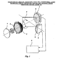
Fig. 1 is a figure for explaining a first embodiment of
the polarization direction detection type two-dimensional
light reception timing detection device of the present
invention.
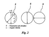
Fig. 2 is a figure for explaining polarization axis
directions of a polarizer and analyzers of the first embodiment
of the polarization direction detection type two-dimensional
light reception timing detection device.
Fig. 3 is a figure showing change of the incident light
intensity after the light has passed through the analyzers in
the first embodiment of the polarization direction detection
type two-dimensional light reception timing detection device.
Fig. 4 is a figure showing change of the light intensity
ratio after the light has passed through the analyzers in the
first embodiment of the polarization direction detection type
two-dimensional light reception timing detection device.
Fig. 5 is a figure for explaining a second embodiment of
the polarization direction detection type two-dimensional
light reception timing detection device of this invention.
Fig. 6 is a figure for explaining the polarization axis
directions of the polarizer and the analyzers in the second
embodiment of the polarization direction detection type
two-dimensional light reception timing detection device.
Fig. 7 is a figure showing change of the incident light
intensity after the light has passed through the analyzers in
the second embodiment of the polarization direction detection
type two-dimensional light reception timing detection device.
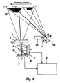
Fig. 8 is a figure for explaining the light section surface
form measurement system of the present invention.
Fig. 9 is a figure for explaining the function of the light
section surface form measurement system of the present
invention.
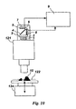
Fig. 10 is a figure for explaining the confocal surface
form measurement system of the present invention.
Fig. 11 is a figure for explaining the conventional light
section surface form measurement system.
Fig. 12 is a figure for explaining the conventional
confocal surface form measurement system.
Fig. 13 is a figure for explaining the conventional grating
projection phase shift surface form measurement system.
Fig. 14 is a figure for explaining the sinusoidal grating
used in the conventional grating projection phase shift surface
form measurement system.
Explanation of Symbols
1 Depolarizing means
2 Polarizer
3 Rotation mechanism
4 Non-polarizing beam splitter
5 and 6 Analyzer
7 and 8 Charge type imaging device
9 Image analysis device
10 Object
111 Laser slit light source
112 Scanning mechanism
113 Imaging lens
114 Television camera
115 Image processing device
116 Display device
121 Confocal imaging system
122 Position in focus
123 Detector
124 Z stage
502,503, and 504 Analyzer
505,506, and 507 Charge type imaging device
BEST MODE FOR CARRYING OUT THE INVENTION
Hereafter, with reference to the drawings, the form of the
embodiment of this invention will be explained in detail. The
first embodiment of the polarization direction detection type
two-dimensional light reception timing detection device of the
present invention is shown in Fig. 1.
Light propagated from the left-hand side is depolarized
by a depolarizing means 1. If the incident light is light with
a certain bandwidth, a so called "Lyot" depolarizer suits the
depolarizing means 1, which is made of two crystals, one of which
is a few times thicker than the other, bonded together in such
a way that the angle made by the two optical axes is 45 degrees.
Or if the incident light is linearlypolarized to a certain angle,
a 1/4 wave plate and the like may be used. It is necessary to
merely provide light which does not change a great deal in
intensity by the direction of the polarization when the light
is linearly polarized. It does not, however, need to be
completely depolarized. For example, it is sufficient also
when the light is circularly polarized, by a 1/4 wave plate,
as mentioned above. Moreover, there is, in some cases, no need
to use a depolarizing means 1, since the incident light itself
is already in a depolarized state because of the character of
the light source and an object to be used. Moreover, depending
on the kind of linear polarization rotation means explained
below, there is no need to depolarize the light.
Depolarized light (or circularly polarized light) is
incident on a linear polarization rotation means which consists
of a polarizer 2 and its rotation mechanism 3, and turns into
linear polarized light, the direction of the polarization
rotates as time progresses. The linear polarization rotation
means may be realized by elements with electro-optic effect,
magneto-optic effect, or the like so that the axis direction
of the linear polarized light is rotated (optical rotation) as
time progresses. For example, since the liquid crystal has
optical rotational power, it can rotate the polarization
direction of the linear polarized light after passing a fixed
polarizer electrically. In this case, the depolarizing means
1 is unnecessary.
The incident light which became linearly polarized light
with the rotating polarization direction reaches an analyzing
means which consists of a non-polarized beam splitter 4, and
two analyzers 5 and 6 with their optical axes mutually crossing
at a right angle. Regardless of the direction of polarization
using the non-polarizing beam splitter 4, the light wave is
split into two optical waves with the polarization states
remaining as before, and the energy becomes half respectively.
The components which are perpendicular to each other pass
through the individual analyzers 5 and 6, and the intensity of
each component is detected by two charge type imaging devices
7 and 8.
As an analyzing means, a polarizing beam splitter which
has functions of both the non polarizing beam splitter 4 and
analyzers 5 and 6 may, of course, be used because of a lower
optical loss. In order to raise the accuracy of the polarizing
characteristic, not only may the polarization beam splitter be
used, analyzers 5 and 6 may also be used.
Two charge type imaging devices 7 and 8 are disposed
optically in the same position. For example, when the devices
are used with a imaging lens, these are arranged so that the
light reception surface of the charge type imaging devices 7
and 8 may come to the image plane of the imaging lens, and this
optical distance (optical pass length) from the imaging lens
to the two charge type imaging devices 7 and 8 both completely
come to be the same. Moreover the pixels of the same coordinates
(xi, yi) of the charge type imaging devices 7 and 8 correspond
to the same position on the surface of an object. (This is not
an absolute condition. The condition is eased by having a
compensation means. But for the time being, it is assumed that
the above-mentioned condition is fulfilled here.) Moreover,
operation of these two charge type imaging devices 7 and 8 is
synchronized. That is, the release timing of each shutter and
the duration of shutter releasing are always in agreement, and
the obtained images are simultaneously sent to an image analysis
device 9 as electric signals. Inside of the image analysis
device 9, light reception timing is calculated for every pixel
from the two sheets of images obtained simultaneously from the
charge type imaging devices 7 and 8 respectively.
As the charge type imaging device, the most common device
at present is a two-dimensional CCD camera, but any
two-dimensional detection device of all pixel simultaneous
exposure types is appropriate.
The above is the structure of the first embodiment of the
polarization direction detection type two-dimensional light
reception timing detection device. Next, the function of this
device is described. This device can record the timing (time
difference) at which light arrives on each pixel within the
duration of one exposure of the charge type imaging devices 7
and 8 by the direction of polarization.
With reference to Figs. 2-4, the function is explained in
detail. As in Fig. 2, the polarization direction after
passing the linear polarization rotation means rotates at an
angular velocity ω with the initial state parallel to the
polarizer 5. Supposing a continuous light of constant
intensity is incident on the device, the intensity of the
incident light after passing through the two analyzers 5 and
6 will become as shown in Fig. 3. Here, when the polarization
direction is considered only between 0-π/2 after passing
through the linear polarization rotation means, the calculation
of the ratio of incident light intensities (b-a)/(a+b) after
passing through the two analyzers 5 and 6 will be as shown in
Fig. 4, and it becomes almost linear except at both ends, and
more correctly, it changes in a sinusoidal form.
The case of an incoming pulse-light and not a continuous
light is considered. Suppose that the polarization direction
after passing through the linear polarization rotation means
rotates 0-π/2 and the light comes only at the time ti. The
shutters of the charge type imaging devices 7 and 8 are released
in synchronization with a polarization direction rotation.
That is, suppose that while the polarization direction rotates
from 0 to π/2 and the shutters are kept released, the output
of ai and bi will be obtained according to the polarization
direction when the light reaches the charge type imaging
devices 7 and 8 respectively, as shown in Fig. 3. From these
values, i can be obtained by calculation of the ratio of
intensity (b-a)/(a+b), and by correspondence with the Fig. 4.
Moreover the time ti is derived by ti=i/ω. If pulse lights
reach to each pixel at different timings, and if the timings
are within the exposure duration of the charge type imaging
devices 7 and 8, the intensity ratio of each pixel shows the
polarization direction of each timing, thereby the light
reception timing of light can be calculated for every pixel with
the image analysis device 9.
The above is the first embodiment of the polarization
direction detection type two-dimensional light reception
timing detection device. Next, a second embodiment of the
polarization direction detection type two-dimensional light
reception timing detection device is explained using Figs. 5-7.
The second embodiment of the invention of the polarization
direction detection type two-dimensional light reception
timing detection device is shown in Fig. 5. Since the
depolarization means 1 and the linear polarization rotation
means are completely the same as those of the first embodiment,
their explanation is omitted. An incident light that has become
linearly polarized light with the rotating polarization
direction is split by a beam splitter 501 into three directions.
In the first embodiment, the number of division was two, and
the fact that light is divided into three directions differs
from the first embodiment. Although the explanation given
below is for the case where the number of divisions is three,
the number of directions is not necessarily restricted to three.
More than three directions are also acceptable.
A beam splitter 501 as shown in Fig. 5, as an example, is
realizable by using an amplitude division coatat the bonded
portion of a combination prism that is commonly used in a 3 CCD
type color camera. If the flux division ratio of the coat near
the side of the incident light is set to 1:2, and another coat
is set to 1:1, then division into three becomes possible. Four
right-angled prisms can be used by bonding them together. If
a coat with half flux division is used on all bonding planes,
light from an arbitrary direction is projected in an individual
direction with the 1/4 flux.
As shown in Fig. 6, incident light divided into three
reaches analyzing means consisting of three analyzers 502, 503,
and 504, for which the polarization directions differ by π/3,
from each other. Regardless of the direction of polarization,
the polarization state remains as is, and its flux is divided
into 1/3 to 1/4 by a beam splitter 501, and the intensity of
the light which passes through three sheets of analyzers 502,
503, and 504, with the polarization directions differing by π/3,
is detected by three charge type imaging devices 505, 506, and
507.
The three charge type imaging devices 505, 506, and 507
are arranged optically at the same position. For example, in
the case in which these devices are used with a imaging lens,
although these are arranged so that the light reception plane
of the charge type imaging devices 505, 506, and 507 comes to
the image plane of the imaging lens, this optical distance
(optical pass length) from the charge type imaging devices 505,
506, and 507 to the imaging lens becomes completely the same,
and the pixel of the same coordinates (xi, yi) of the charge
type imaging devices 505, 506, and 507 corresponds to the same
position on the object. (This condition is not absolute and
with some compensation means could be eased. For the time being,
explanation is given on the assumption that the above-mentioned
conditions are fulfilled here.) Moreover, operation of these
three charge type imaging devices 505, 506, and 507 is
synchronized. That is, the release timing of each shutter and
the duration of the shutter releasing are always in agreement,
and the obtained images are simultaneously sent to the image
analysis device 9 as electric signals. Inside the image
analysis device 9, light reception timings are calculated for
every pixel from three images obtained simultaneously from the
charge type imaging devices 505, 506, and 507, respectively.
The above is the structure of the second embodiment of the
polarization direction detection type two-dimensional light
reception timing detection device. Next, the function of this
device is described. This device can record the timing (time
difference) at which light arrives on each pixel within one
exposure of the charge type imaging devices 505, 506, and 507,
by the directions of polarization.
With reference to Figs. 6 and 7, the function will be
explained more specifically. As shown in Fig. 6, when the
polarization direction after being subjected to a linear
polarization rotation means rotates at an angular-velocity ω,
supposing that an initial state is parallel to an analyzer 502,
and a continuous light of constant intensity is incident on the
device, the change of the incident light intensity after passing
through three analyzers 502, 503, and 505, is sinusoidal
wave-like as shown in Fig. 7 with a phase shift of 2π/3
(polarization direction π/3)mutually.
Next, the case where the incident light is not continuous
but a pulse is considered. Suppose that the polarization
direction after passing through the linear polarization
direction rotation means rotates continuously, and light is
incident at an instant ti only. Supposing the shutters of the
charge type imaging devices 505, 506, and 507 are released at
the polarization direction = 0 and it is exposed until, for
example, =Nπ, as shown in Fig. 7, the outputs (ai, bi, and ci )
of the charge type imaging devices 505, 506, and 507 are obtained
respectively and the outputs (ai, bi, and ci ) correspond to
the polarization direction i of the timing when the light
enters.. Therefore i can be calculated from these values.
However, one must note that the calculated i contains
indefiniteness of nπ. Specifically, if I is the mean light
intensity and I·γ is the grating pattern amplitude, then
ai=I[1+γ·cos(i-2π/3)], bi=I[1+γ·cos(i)], and
ci=I[1+γ·cos(i+2π/3)], therefore,
i=arctan[√3·(ai-ci)/(2bi-ai-ci)]. Furthermore, the timing
ti can be derived by the operation of ti=/ω (nπ/ω is
indefinite). Suppose pulse light is incident on each pixel at
a different timing. If this is within the duration of the
exposure of the charge type imaging devices 505,506, and 507,
the pixel output of the intensity ratio that shows the
polarization direction at the timing of light reception for
every pixel will be obtained, and the light reception timing
can be calculated for every pixel with the image analysis device
9.
Here, although three analyzers 502, 503, and 504 with a
polarization direction differing by π/3 were considered, this
of course does not limit the present invention. Each interval
of a polarization direction can be π/4, and may be random. The
only requirement is that the polarization directions of
polarizers are known. There could be more than three analyzers,
four or five are also acceptable. The only requirement is to
be able to fit the values to the sinusoidal wave. Using more
values leads to higher phase detection accuracy.
In the first embodiment or in the second embodiment, the
reason why this invention is new and effective is that the timing
when the incident light hits each pixel can be derived with only
one exposure (although a set of images is acquired).
Conventionally, when using a charge type imaging device like
a CCD camera in order to detect the timing of incident light
on each pixel, many images must be taken continuously, and the
image that gives the maximum pixel output is chosen, and from
the number of the image (the order with respect to time), the
light incident timing is derived.
Next, we discuss more specific examples of how the light
section method, the grating projection phase shifting method,
and the confocal method are made faster using the polarization
direction detection type two-dimensional light reception
timing detection device.
Using Fig. 8, we first discuss how to make the light section
method faster. The Fig. 8 shows an example of the first
embodiment of this invention of the polarization direction
detection type two-dimensional light reception timing
detection device applied to a conventional system of the light
section method. The principle of measurement of relief on an
object 10 is the same with the conventional system. That is,
a slit light is projected on the object 10 at an angle different
from the optical axis of an imaging lens 113 and scanned by a
scanning means 112 over the whole field of view determined by
the imaging lens 113 and a charge type imaging devices 7 and
8. By detecting the timing of light incident on each pixel in
the charge type imaging devices 7 and 8 (or of the slit light
passing the object 10 surface point corresponding to the pixel),
the angle of the slit light is derived from the timing. The
position of the surface of the object 10 is calculated as the
crossing point of the two lines; one line is made by the chief
ray of the imaging lens 113 incident to the pixel, and another
line is made by the slit light with the angle determined as above.
In the example like this light section method of the slit
light scan type, if we set aside special cases such as multiple
reflections due to the gloss of the object 10 surface or having
two or more reflective surfaces in the optical axis direction
like a film or glass plate, the only time at which a light is
incident on a certain pixel is when the slit light passes the
corresponding point on the object surface, and that is only once
in a scanning over one field of view.
If, while the shutters (electronic shutter) of the charge
type imaging devices 7 and 8 are kept released, the direction
of the linear polarization light incident to the analyzers can
be rotated in synchronization with the slit light scanning over
the whole field of view from the left end to the right end of
Fig. 8 (for example, when the slit light is at the right end,
the polarization direction is 0, and when the slit light is at
the left end, the polarization direction is π/2, and between
them, it rotates at a constant angular velocity ω), lights like
pulse are incident on each pixel only when the slit light passes
the corresponding surface position of the object 10 and when
the scanning of the slit light is completed and the shutter
of the charge type imaging devices 7 and 8 are shut, the intensity
ratio which shows the polarization direction when the incident
light hits the pixel will be recorded at each pair of pixels
of the charge type imaging devices 7 and 8.
Fig. 9 shows the state in which, at the timing tp, the light
hits a pair of pixels P' and P" in the charge type imaging devices
7 and 8 (when the slit light passes the corresponding point on
the surface of an object) in Fig. 8, in which the horizontal
axis indicates the polarization direction. Since lights are
incident on the charge type imaging devices 7 and 8 only at the
timing of tp, output values can be obtained which are
proportional to the light intensity ai and bi, corresponding
to the polarization direction i at the time. i is derived
from the intensity ratio (bi-ai)/(ai+bi), and the timing can
be calculated by the formula ti=i/ω.
If light reception timing of all pixels is obtained as
mentioned above, the height (Z position) of the object 10
surface corresponding to each pixel can be calculated by easy
processing of the image analysis device 9, since the following
information can be obtained in advance: the relation of the
timing and the projection angle of the slit light, the chief
ray angle of the imaging lens 113 as that ray hits each pixel,
and the geometrical arrangement between the imaging lens 113
and the scanning mechanism 112.
If all the combinations of ai and bi for every pixel are
calculated and stored in a table in advance, the output value
of the charge type imaging devices 7 and 8 can also be changed
directly into the surface height of the object 10 by merely using
the table. Of course, it is also possible to constitute a
reference table with the values of the intensity ratio
(bi-ai) / (ai+bi). At any rate, since calculation of the surface
form of an object 10 is very simple, even by software processing,
sufficient video rate measurement of the surface form of an
object 10 can be realized by using a high-speed CPU.
The implementability of hardware parts of the system is
now examined briefly. Suppose a Galvano scanner is used as a
scanning mechanism 112, less than 1 ms of the scan over one field
of view is possible and one quarter rotation (0 - π / 2
polarization direction rotation) within 1ms (15000rpm) is
easily performed if a motor is used as a polarization rotation
means. That is, not only measurement of the video rate (33ms)
is possible, but three-dimensional freezing measurement (which
correspond to high-speed shutter operation of a camera) of
moving objects is also possible.
Next, measurement resolution ability is considered. The
measurement resolution ability is obviously restricted by the
angle detection resolution ability of a projection slit. The
number of divisions within the scanning angle range is important,
but as is clear from Fig. 3, since the device can be only used
in the domain of the monotone increasing or decreasing, the
number of divisions can not normally exceed the quantization
number (gradation number) S of a image, which number is
detection values of the detector that varies from 0 to S. In
fact, it will become much smaller than S due to heterogeneity
of reflectance of the object or the noise factor due to various
causes.
The case that the second embodiment is applied to the
system as the polarization direction detection type
two-dimensional light reception timing detection device is
considered hereafter. In the case of the second embodiment as
shown in Fig. 7, the domain is not restricted in the monotone
increasing or decreasing region, at least the range from 0 to
π can be used, and if the indefiniteness of nπ is permitted,
the domain over more than two cycles can be used, thus a very
fine angle detection resolution can be provided. For example,
supposing N cycle domain is used, a slit will be scanned from
one end of a image to the other within one exposure time of the
charge type imaging devices 505, 506, and 507, and the polarizer
2 will rotate N/2 times. In this way, sinusoidal grating
pattern images with N fringes are obtained and the phase of
grating of each three images has shifted mutually. That is,
if one takes only the obtained images into account, images
completely the same as the ones obtained from the grating
projection phase shifting method are obtained. If processing
equivalent to that used in the grating projection phase shifting
method is applied, measurement of the same accuracy as the
grating projection phase shifting method can naturally be
performed. All are not the same necessarily. Projected
patterns may not be sinusoidal patterns which are difficult to
manufacture, a rectangle-slit is sufficient. Since three phase
shift images can be obtained simultaneously, a good
characteristic is provided, in that the measurement for moving
objects is possible. Moreover, the number of slits does not
need to be one. For example, if N slits are provided, the
scanning range becomes 1/N and light intensity is
quantitatively advantageous. When two or more slit lights are
projected, the direction of polarization must be made to become
the same at the beginning of a scan as at the end of the scan,
that is, the direction is a multiple of π.
Next, improvement in the speed of the confocal method is
explained using Fig. 10. In the conventional device using the
confocal method in Fig. 12, the polarization direction
detection type two-dimensional light reception timing
detection device of the first embodiment is used instead of the
usual detector 123. As stated above, the confocal imaging
system 121 has the feature where only light from a portion in
focus arrives at the charge type imaging devices 7 and 8 as
reflective light of an object 10, while hardly any light from
a portion out of focus reaches the charge type imaging devices
7 and 8. Therefore, as the object 10 is scanned in the direction
of the optical axis with the Z table 124, light reaches the pixel
only when the surface of the object 10 passes the conjugate
position (the three dimensional imaging position of the pixel
in the object side of the objective lens) of each pixel of the
charge type imaging devices 7 and 8, and at other timing, light
will not reach the pixel. The timing at the light reception
will express the position of the Z table 124 at that time, and
the position will show the relative position of the surface of
an object 10 in the optical axis direction.
Although calculation methods to convert the light
reception timing to the surface height of the object 10 differ
completely, light hits each pixel of the charge type imaging
devices 7 and 8 just once in a pulse. Therefore the surface
position is derived from the timing, and it is completely the
same as that of the example of the light section method mentioned
above.
While the shutters of the charge type imaging devices 7
and 8 are released in synchronization with scanning of the Z
table 124 over the whole measurement range ( from top to bottom
in Fig. 10), if the direction of linear polarization incident
to the analyzing means is rotated by linear polarization
rotation means (for example, the direction of polarization is
zero at the top end of the Z table, and π/2 at the bottom, in
between, it rotates with a constant angular velocity ω), at
each pixel, light enters as a pulse only when the surface of
the object 10 passes the conjugate position and when a scan of
the Z table 124 is completed and the shutters of the charge type
imaging devices 7 and 8 are shut, the intensity ratio which shows
the polarization direction at the time of light hitting each
pair of pixels of the charge type imaging devices 7 and 8 will
be recorded. All that is necessary is to convert back to the
surface height of the object 10 on the image analysis device
9.
Also in the confocal method, in order to raise measurement
resolution ability, the second embodiment of the polarization
direction detection type two-dimensional light reception
timing detection device can be introduced. All that is
necessary is to rotate the polarizer 2 as many times as possible
during one exposure/scan, and derive the position (namely,
object surface position) at which light is reflected, as an
initial phase from the three images with different phases.
However, since the indefiniteness of nπ exists, phase
connection processing is needed.
Next, the time of flight method (hereinafter referred to
as "TOF method") similarly known as the surface formmeasurement
technique is considered. The TOF method is also realizable by
the polarization direction detection type two-dimensional
light reception timing detection device. The TOF method is a
technique of measuring the relief on the surface of an object
by measuring the time interval from light emission until it is
reflected by the object and returned. Since this invention is
a technique for measuring time, this invention is applicable.
That is, pulse-light is irradiated simultaneously at the whole
object and returning light is received at the polarization
direction detection type two-dimensional light reception
timing detection device through an imaging lens. Since the time
after the light is emitted and returned differs according to
the object surface' s relief, the time difference can be measured
with the polarization direction detection type two-dimensional
light reception timing detection device, and thereby, an object
surface form can be determined.
Although examples of the polarization direction detection
type two-dimensional light reception timing detection device
applied to surface form measurement were shown, the scope of
the polarization direction detection type two-dimensional
light reception timing detection device is not limited only to
these cases. The invention can apply to phenomenon where
two-dimensional position is important and at each position,
light is radiated or reflected/penetrated only as a pulse. For
example, applications to locus measurement of a high-speed
moving object, visible light communications, or the like can
also be considered.
INDUSTRIAL APPLICABILITY
By this invention, with only one time of imaging (one
exposure) , one can detect light reception timing for every pixel,
and more than several to a few hundred times faster measurement
of the surface form measurement is possible than with the
conventional methods concerned with the light section method,
the grating projection phase shifting method, the confocal
method, and the TOF method. Since measurement of moving objects
becomes possible, a large effect in extensive fields, such as
three dimensional high-speed phenomenon analysis, the
three-dimensional vision for a robot or a car, the three
dimensional measurement of living bodies of animals and plants,
security, and FA is expected.