EP1482244A1 - Counterflow fuel injection nozzle in a burner-boiler system - Google Patents
Counterflow fuel injection nozzle in a burner-boiler system Download PDFInfo
- Publication number
- EP1482244A1 EP1482244A1 EP20040460016 EP04460016A EP1482244A1 EP 1482244 A1 EP1482244 A1 EP 1482244A1 EP 20040460016 EP20040460016 EP 20040460016 EP 04460016 A EP04460016 A EP 04460016A EP 1482244 A1 EP1482244 A1 EP 1482244A1
- Authority
- EP
- European Patent Office
- Prior art keywords
- fuel
- nozzle
- counterflow
- injection
- interior
- Prior art date
- Legal status (The legal status is an assumption and is not a legal conclusion. Google has not performed a legal analysis and makes no representation as to the accuracy of the status listed.)
- Withdrawn
Links
Images


Classifications
-
- F—MECHANICAL ENGINEERING; LIGHTING; HEATING; WEAPONS; BLASTING
- F23—COMBUSTION APPARATUS; COMBUSTION PROCESSES
- F23C—METHODS OR APPARATUS FOR COMBUSTION USING FLUID FUEL OR SOLID FUEL SUSPENDED IN A CARRIER GAS OR AIR
- F23C7/00—Combustion apparatus characterised by arrangements for air supply
- F23C7/002—Combustion apparatus characterised by arrangements for air supply the air being submitted to a rotary or spinning motion
- F23C7/004—Combustion apparatus characterised by arrangements for air supply the air being submitted to a rotary or spinning motion using vanes
-
- F—MECHANICAL ENGINEERING; LIGHTING; HEATING; WEAPONS; BLASTING
- F23—COMBUSTION APPARATUS; COMBUSTION PROCESSES
- F23D—BURNERS
- F23D14/00—Burners for combustion of a gas, e.g. of a gas stored under pressure as a liquid
- F23D14/02—Premix gas burners, i.e. in which gaseous fuel is mixed with combustion air upstream of the combustion zone
-
- F—MECHANICAL ENGINEERING; LIGHTING; HEATING; WEAPONS; BLASTING
- F23—COMBUSTION APPARATUS; COMBUSTION PROCESSES
- F23D—BURNERS
- F23D14/00—Burners for combustion of a gas, e.g. of a gas stored under pressure as a liquid
- F23D14/46—Details
- F23D14/48—Nozzles
- F23D14/58—Nozzles characterised by the shape or arrangement of the outlet or outlets from the nozzle, e.g. of annular configuration
-
- F—MECHANICAL ENGINEERING; LIGHTING; HEATING; WEAPONS; BLASTING
- F23—COMBUSTION APPARATUS; COMBUSTION PROCESSES
- F23C—METHODS OR APPARATUS FOR COMBUSTION USING FLUID FUEL OR SOLID FUEL SUSPENDED IN A CARRIER GAS OR AIR
- F23C2202/00—Fluegas recirculation
- F23C2202/30—Premixing fluegas with combustion air
Definitions
- the field of the invention relates generally to fuel injection nozzles, and more particularly, to a counterflow fuel injection nozzle.
- Burners are used in boilers, heaters, and other applications for the conversion of fuel to heat. The heat is then transferred to make hot water, steam, and/or warm air, or to create power, depending upon the application.
- a burner-boiler system e.g., firetube and commercial and industrial watertube boilers
- fuel is typically injected through nozzles to create a flame.
- the fuel is combined with air flowing around or adjacent the nozzle.
- the fuel is ignited to create a flame, with a goal being to maximize the conversion of the fuel that is burned during this combustion process so as to achieve complete combustion.
- the manner in which the fuel is injected (i.e., its direction, velocity, and interaction with other fluid streams) into the air stream affects the flame profile or shape and thus greatly determines the completeness of the combustion and heat release into the furnace.
- the injection method affects the overall geometry and physical characteristics of the nozzle itself.
- the fuel is typically injected through passageway(s) formed in the nozzle, and more particularly, the nozzle body. These physical characteristics include the width or diameter, spacing, and angling or pitch of the particular passageway(s) or channel(s).
- a counterflow fuel injection nozzle for injecting fuel
- the nozzle comprising: a nozzle wall having an interior surface that defines a nozzle interior. The interior for receiving a fuel therein, the nozzle further having a fuel passageway formed in the nozzle wall for distributing the fuel from the interior to a location exterior of the nozzle, the fuel distributed to the exterior location in a fuel flow injection direction.
- a fuel passageway formed in the nozzle wall for distributing the fuel from the interior to a location exterior of the nozzle, the fuel distributed to the exterior location in a fuel flow injection direction.
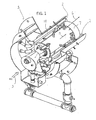
- Fig. 1 is perspective partially cut-away view of a burner 1 incorporating an embodiment of a counterflow fuel injection nozzle 2 of the present invention.
- Burner 1 can receive a gaseous fuel (e.g., propane, natural gas, etc.) from a fuel source (not shown) via a fuel line or pipe (also not shown) and delivery within the burner via lance 14.
- a gaseous fuel e.g., propane, natural gas, etc.
- Fuel line or pipe also not shown
- Total combustion air flow is indicated by arrow 3, with primary air 4, secondary air 5, and tertiary air 6 flowing through other paths (as directed at the burner entrance, for example, around a diffuser 7 and between injection nozzles) to promote complete combustion.
- the air flows may have, in addition to air, flue gas products (FGR).
- FGR flue gas products
- the O 2 levels are lower in flue gas products than in air.
- Oxygen levels can preferably be in the range of 11-21%, more preferably in the 15-21% range, and most preferably in the 16-19% range.
- Fig. 1a is a front view of a burner incorporating an embodiment of the counterflow fuel injection nozzle of the present invention and Fig. 2a is a side elevational view taken along line 2a-2a of Fig.1a.
- fuel is introduced into the burner 10 at a number of locations via manifold 11. More specifically, fuel is introduced via a plurality of radially disposed fuel lines or lances 14.
- central injection pipe 13 is used for distributing fuel via nozzles 15 to create a flame in the center of the burner.
- Burner 10 further includes a diffuser (also called a "swirler”), generally referred to by numeral 18, having blades 20.
- a diffuser also called a "swirler”
- Tertiary air is introduced into burner 10, also indicated by numeral 6, and diffuser 18 imparts a rotating motion to the air so as to increase mixing of the air and the fuel.
- the radially disposed lances 14 terminate with injection nozzles 16, also referred to herein as simply "injectors" or "nozzles".
- injectors also referred to herein as simply "injectors” or "nozzles”.
- the distance 19 between the head 17 of nozzle 16 and the beginning of the diffuser plane area 21 is an important factor for successful application of the nozzle 16 as it will affect mixing capabilities of the fuel and air.
- the gap between nozzle 16 and outer ring 25, as indicated by arrow 27, is also important for mixing capabilities.
- the "prevailing air flow direction" corresponds to an air flow direction in which the air travels from a location generally upstream of the fuel injectors to a location generally downstream of the fuel injectors.
- the flow of air can be influenced by structures or "bluff bodies" within the burner itself (e.g., the diffuser, manifolds, fuel lines, etc.). As will be described in greater detail below, and as shown in Fig. 1, at least a portion of the air flow is directed or distributed past the diffuser and generally along or past the nozzles 16.
- Fig. 2b is a diagram schematically illustrating the concept of counterflow with respect to a representation of the present inventive counterflow fuel injection nozzle.
- fuel flows into the nozzle 510 in an initial fuel flow direction 518 and flows into the interior 514 of the nozzle.
- Fuel is distributed from the nozzle interior 514 along a fuel flow injection direction 520 (F fuel ).
- the fuel is typically injected at a preferred pressure of up to 20 psig.
- “Fuel flow injection angle” is that angle at which the fuel is injected out of the counterflow fuel injection nozzle, and more specifically, the nozzle interior, via apertures, holes, or openings 516a-b to a location exterior of the nozzle.
- Fuel flow injection direction is determined by the fuel flow injection angle ⁇ at which fuel is distributed from the nozzle interior.
- the trajectory is determined by the angle, as well as the fuel and the air velocity. As shown, the angle is measured from a plane that is normal or perpendicular to the surface of the nozzle.
- Fuel flowing along fuel flow injection direction 520 includes a perpendicular flow vector component 522 ( ) and a counterflow vector component 524 ( ).
- perpendicular it is meant that the vector component is perpendicular to the prevailing air flow direction, and by “counterflow” it is meant that the vector component opposes the prevailing air flow direction.
- the fuel is injected along the fuel injection direction 520 into air flowing in a prevailing air flow direction 526 (F air ).
- Mixing typically occurs at a location exterior of the nozzle.
- the fuel flow injection direction vector is shown in schematic fashion to illustrate the fuel flow injection angle with greater clarity, but that the fuel flow trajectory takes on a more complex path (i.e., it curves or swirls) due to the injection of the fuel into the prevailing air flow and as the distance the fuel travels from the nozzle increases. This more complex path is indicated by the arrow 525.
- a "counterflow angle” exists when at least one vector component (i.e., a counterflow fuel vector component) of the fuel flow injection direction is opposite at least one vector component of the prevailing air flow direction (i.e., a counterflow air vector component).
- counterflow fuel vector component 524 opposes or is opposite (and thus flows counter to) at least one counterflow air vector component of the prevailing air flow direction 526.
- a significant purpose for distributing fuel into an air flow to create a counterflow angle is to achieve, or to substantially achieve, complete mixing of the fuel in the air.
- the spectrum of fuel flow injection angles ⁇ ranges from about 15 degrees to about 90 degrees (i.e., with 90 degrees meaning complete counterflow).
- the counterflow angle is about 30 degrees.
- Fig. 3 is an enlarged sectional view taken along line 3-3 of Fig.2a, in particular, illustrating a sectional view of nozzle 16 according to one aspect of the present invention in greater detail.
- Fig. 4 is a perspective view of one embodiment of the counterflow fuel injection nozzle according to one aspect of the present invention.
- Injection nozzle 16 includes a nozzle body 28.
- Fig. 5 is a bottom sectional view taken along line 5-5 of Fig. 3.
- the nozzle body 28 has a nozzle wall 30, and the nozzle wall 30 defines a nozzle interior 32.
- nozzle 16 is generally "T"-shaped. It is nozzle interior 32 that receives the fuel to be distributed and ultimately injected into to the airstream to produce a flame. Since nozzle interior 32 acts as a fuel conduit, the hole shape, hole diameters, hole distribution and injection angles all contribute to how the fuel is distributed throughout the nozzle interior 32.
- the embodiment shown is representative only, and it is contemplated that other shapes, geometric features and body outlines could be suitably employed. That is, the nozzle may have other particularized curves, tapers, angles, and interior surface and interior geometries and still accomplish the objectives of the injection nozzle 16.
- Nozzle body 28 further includes a series of fuel passageways 40 terminating in holes or openings 42 formed in the nozzle wall for distributing the fuel from the interior.
- the size of the nozzle holes are critical, since, if the holes are too small, "fouling" and other similar problems may occur.
- One factor in determining the appropriate size, shape and placement of holes and passages is the position of the nozzle relative the air flow.
- Another factor is the geometry of the nozzle itself. Hole placement can be selected to promote mixing by distributing fuel into the prevailing air flow. The result is that the air is entrained (carried in a current) within the fuel to achieve better mixing.
- the goal is to achieve uniform mixing, and it has been found that more uniform mixing results from a wide dispersal of fuel into an air flow.
- a representative passageways and placement of holes are shown in a representative nozzle.
- Fuel is injected along a fuel injection direction 40.
- Representative fuel injection trajectories are illustrated by arrows 44.
- the passageways can be cylindrical and the holes can be round.
- the holes can be sized to have a diameter in a range of from about 0.0625 inches to about 0.141 inches.
- the holes can be spaced apart, as measured from their respective centers, from about 0.325 to about .75 inches, with an exemplary hole distance of 0.5 inches apart.
- a design goal to select the size, shape and placement of the holes in the nozzle to minimize, or substantially eliminate, interference between the holes (e.g., one fuel injection direction crossing, in whole or in part, another fuel injection direction).
- the distance between the holes of an exemplary nozzle is L and the diameter of the holes is D.
- the ratio L/D will define the interaction between adjacent holes.
- the diameter of the holes will determine the penetration depth of the fuel (gas) and overall fuel distribution patterns. L determines whether the adjacent fuel jets result in mixing or combining of the fuel streams.
- exemplary penetration depth of fuel and fuel distribution patterns x1 and x2 are illustrated for 2 holes y and z of different hole diameters.
- the variations of size, shape and placement of the holes can be from nozzle to nozzle (i.e., for a given nozzle the holes and spacings are identical), or the size, shape and placement can vary from hole to hole.
- the ratio of L to D is about 5.
- the counterflow angle i.e., the angle created by the fuel flow injection direction with respect to the prevailing air flow direction
- the counterflow angle also effects the air/fuel mixing location and permits control over whether mixing occurs more or less downstream of the nozzles. This can be advantageous for a variety of reasons. For example, by keeping the mixing of the air and fuel further downstream of the nozzles, the flame can be created further downstream, and the nozzle can be protected from exposure to high levels of heat. This can serve to prevent the nozzles from burning out prematurely.
- the size, number and placement of passages and holes in the nozzle body permits flame sculpting (also called flame shaping, or flame forming) to achieve optimum mixing in relation to the furnace geometry.
- flame sculpting also called flame shaping, or flame forming
- counterflow angle selection is dependant upon such conditions as the burner air flow distribution, direction and velocity.
- Fig. 6 is a perspective view of another embodiment of a counterflow fuel injection nozzle according to one aspect of the present invention.
- Fig. 7 is a side sectional view of the counterflow fuel injection nozzle of Fig. 6 and
- Fig. 8 is a bottom sectional view taken along line 8-8 of Fig. 7.
- Figs. 6-8 also illustrate exemplary counterflow injection angles.
- the nozzle body 128 has a nozzle wall 130, and the nozzle wall 130 defines a nozzle body interior 132.
- nozzle 116 is generally "Truncated T-shaped" in that it is truncated when compared to the embodiment of Figs. 3-5. It is nozzle body interior 132 that receives the fuel to be distributed and ultimately injected in the airstream to produce a flame. Since nozzle body interior 132 acts as a fuel conduit, the hole shapes, as with the other embodiments, the hole diameters, hole distribution and injection angles all contribute to how the fuel is distributed throughout the nozzle interior 132. The embodiment shown is representative only, and it is contemplated that other shapes, geometric features and body outlines could be suitably employed.
- any suitable materials may be used in the construction of injection nozzle 116, although stainless steel is one preferred material, among others.
- Interior surface 134 of nozzle wall 130 defines nozzle interior 132 into which fuel is received from fuel line 114.
- Fuel line 114 includes an optional threaded portion 136 for threaded insertion into a mating threaded portion 138 of interior surface 134 if a threaded connection is desired. Although a threaded engagement is shown and preferred, it is contemplated that other means of connection between the fuel line 114 and the injection nozzle 116 are possible.
- Nozzle body 128 further includes a series of fuel passageways 140 terminating in holes or openings 142 formed in the nozzle wall for distributing the fuel from the interior.
- fuel flows from the nozzle interior 132 through the passageways 140 and out of the nozzle 116 via holes 142 into an air flow (again, see Figs. 1-2).
- the size, shape, and placement of the holes and passageways can be varied to achieve the desired mixing effect (i.e., mixing between the air and the fuel injected into the air). Again, hole placement will be selected to promote mixing by distributing fuel into the prevailing air flow.
- Fig. 9 is a perspective view of another embodiment of the counterflow fuel injection nozzle according to one aspect of the present invention.
- One design parameter of the embodiment of Fig. 9 is the limited footprint shown, such that the nozzle shown could be incorporated into smaller burners, particularly where the insertion of a larger area T or other shaped nozzle would not fit properly into the space provided.
- Fig. 10 is a side sectional view of the counterflow fuel injection nozzle of Fig. 9.
- Fig. 11 is a front sectional view taken along line 11-11 of Fig. 10.
- Figs. 9-11 illustrate exemplary fuel flow injection angles and angular hole spacing.
- the nozzle body 228 has a nozzle wall 230, and the nozzle wall 230 defines a nozzle body interior 232.
- nozzle 216 includes several contours which define a primary centralized circumferentially disposed notch or groove 233 which defines a surface 235.
- the shape of the nozzle is generally termed herein "mushroom-shaped".
- injection nozzle 216 The embodiment shown is representative only, and it is contemplated that other shapes, geometric features and body outlines could be suitably employed. Also, any suitable materials may be used in the construction of injection nozzle 216, although steel is one preferred material, among others. Interior surface 234 of nozzle wall 230 defines nozzle interior 232 into which fuel is received from fuel line 214. Fuel line 214 includes threaded portion 236 for threaded insertion into a mating threaded portion 238 of interior surface 234. Although a threaded engagement is shown and preferred, it is contemplated that other means of connection between the fuel line 214 and the injection nozzle 216 are possible.
- Nozzle body 228 further includes a series of fuel passageways 240 terminating in holes or openings 242 formed in the nozzle wall for distributing the fuel, and more particularly, the holes are formed in the surface 235 of primary centralized circumferentially disposed notch or groove 233.
- fuel flows from the nozzle interior 232 through the passageways 240 and out of the nozzle 216 via holes 242 into an air flow (again, see Figs. 1-2). It is contemplated that the size, shape, and placement of the holes and passageways can be varied to achieve the desired mixing effect. Here too, hole placement will be selected to promote mixing by distributing fuel into the prevailing air flow.
- FIG. 9-11 representative passageways and placement of holes are shown in a representative nozzle.
- Fuel is injected along a fuel injection direction 244.
- Representative fuel injection trajectories are illustrated by arrows 244.
- Fig. 12 is a perspective view of another embodiment of the counterflow fuel injection nozzle 416 according to one aspect of the present invention.
- Fig. 13 is a side sectional view of the counterflow fuel injection nozzle 416 of Fig. 12.
- Figs. 12-13 also illustrate fuel injection and counterflow fuel injection trajectories.
- the nozzle body 428 has a nozzle wall 430, and the nozzle wall 430 defines a nozzle interior 432. It is nozzle body interior 432 that receives the fuel to be distributed and ultimately injected into the airstream to produce a flame. Since nozzle body interior 432 acts as a fuel conduit, the particularized curves, tapers angles and surface and interior geometry of the injection nozzle 416 will dictate how the fuel is distributed throughout the nozzle body interior 432.
- the embodiment shown is representative only, and it is contemplated that other shapes, geometric features and body outlines could be suitably employed.
- any suitable materials may be used in the construction of injection nozzle 416, although stainless steel is one preferred material, among others.
- Interior surface 434 of nozzle wall 430 defines nozzle interior 432 into which fuel is received from fuel line 414.
- Fuel line 414 includes threaded portion 436 for threaded insertion into a mating threaded portion 438 of interior surface 434. Although a threaded engagement is shown and preferred, it is contemplated that other means of connection between the fuel line 414 and the injection nozzle 416 are possible.
- Nozzle body 428 further includes a series of fuel passageways 440 terminating in holes or openings 442 formed in the nozzle wall 430, and more specifically, groove 433, for distributing the fuel. Groove 433 prevents air from shearing off the gas exiting the holes and permitting gas to develop into a jet stream, resulting in more consistent mixing.
- the passageways can be cylindrical and the holes can be round.
- the holes can be sized to have a diameter in a range of from about 0.0625 inches to about 0.141 inches. Angular spacing of the holes ranges, in one embodiment, from between about 45 degrees to about 60 degrees. It is contemplated that variations in size, shape and placement can be on a hole by hole and/or nozzle by nozzle basis.
- Hole pattern i.e, the number and position of the holes
- hole size e.g., as determined by hole diameter
- nozzle 500 includes an outer threaded surface 502 with retaining nut 504 threaded thereon to secure nozzle 500 against burner housing portion 506, such as by engaging slot 507 and rotating nozzle 500 appropriately.
- Nozzle 500 includes a bored out portion, channel or passageway 508 (shown in phantom) terminating in nozzle opening 509. Fuel enters fuel passageway 508 in a direction indicated by arrow 512, and proceeds through passageway 508, where it is flows out of the nozzle into an airflow via nozzle opening 509. Fuel is injected at a fuel flow injection direction (F fuel ) into a prevailing air direction (F air ). Again, the fuel is injected through nozzle opening 509 such that at least a component of F fuel is opposite to F air .
- F fuel fuel flow injection direction
- F air prevailing air direction
- More localized mixing can occur at each counterflow injection nozzle, and more specifically, via the holes through which fuel is distributed or dispersed from each nozzle into the prevailing air flow.
- the amount or level of mixing, as well as the location(s) at which mixing takes place can be adjusted or varied to convenience by varying the size and location of the holes.
- each of the above-described embodiments of the inventive counterflow fuel injection nozzles can include plurality of passageways, each having a unique noninterfering fuel injection direction.
- noninterfering it is meant that, at the point at which fuel exits the nozzles (via the nozzle openings), fuel from one passageway having a direction tends not cross the direction of fuel passing from another passageway.
- the holes can also be directed at various angles to achieve the desired mixing qualities.
- a method of mixing a fuel and air in a burner-boiler system comprises a nozzle having a nozzle wall that defines a nozzle interior for receiving the fuel, and the nozzle further includes a fuel passageway formed in the nozzle wall.
- the method comprises passing air in a prevailing airstream direction along an exterior of the nozzle wall.
- the method further includes distributing the fuel in a fuel flow injection direction from the interior through the fuel passageway into the air passing in the prevailing airstream direction along the exterior of the nozzle wall.
- the method still further includes counterflow mixing the fuel distributed in the fuel flow injection direction with the air passing in the prevailing airstream direction.
- at least one vector component of the fuel flow injection direction opposes at least one vector component of the prevailing airstream direction.
- the use of the counterflow nozzle provides additional burner stability with increased flue-gas recirculation (FGR) rates (when FGR is used) to achieve lower NOx levels.
- FGR flue-gas recirculation
- the turndown ratio is the ratio of maximum fuel input rate to minimum fuel rate of a variable input burner, and depends on burner size and control methodology.
- Typical low NOx burners have limited turndown, but with this invention, advantageously, with low NOx operation a higher turndown ratio is possible, and a turndown of from about 7 to 1 to about 10 to 1 has been achieved using the present counterflow injection nozzles.
- a gas mixing nozzle retrofit for a burner used with a firetube boiler, commercial watertube or larger industrial watertube boiler is contemplated.
- the retrofit may be part of a kit that includes a counterflow fuel injection nozzle that is used to replace a non-counterflow fuel injection nozzle.
- a non-counterflow fuel injection nozzle would not provide for at least one vector component of a fuel flow injection direction that opposes at least one vector component of a prevailing air flow direction when an airstream is provided in a prevailing air flow direction in a location exterior of the nozzle.
Landscapes
- Engineering & Computer Science (AREA)
- Chemical & Material Sciences (AREA)
- Combustion & Propulsion (AREA)
- Mechanical Engineering (AREA)
- General Engineering & Computer Science (AREA)
- Gas Burners (AREA)
- Nozzles For Spraying Of Liquid Fuel (AREA)
Abstract
The nozzle has a nozzle wall with an interior surface defining a nozzle interior. A fuel passageway formed in the wall distributes the fuel from the interior to a location exterior of the nozzle in a fuel flow injection direction. A vector component (522) of the direction opposes a vector component (524) of a prevailing air flow direction, when an airstream is provided in a prevailing direction in the location. Independent claims are also included for the following: (a) a method of mixing a fuel and air in a burner system (b) a burner system.
Description
- This application claims the benefit of the filing date of United States application Serial No. 60/474,470, filed on May 31, 2003, now pending.
- The field of the invention relates generally to fuel injection nozzles, and more particularly, to a counterflow fuel injection nozzle.
- Burners are used in boilers, heaters, and other applications for the conversion of fuel to heat. The heat is then transferred to make hot water, steam, and/or warm air, or to create power, depending upon the application. In a burner-boiler system (e.g., firetube and commercial and industrial watertube boilers), fuel is typically injected through nozzles to create a flame. The fuel is combined with air flowing around or adjacent the nozzle. Ultimately, the fuel is ignited to create a flame, with a goal being to maximize the conversion of the fuel that is burned during this combustion process so as to achieve complete combustion. The manner in which the fuel is injected (i.e., its direction, velocity, and interaction with other fluid streams) into the air stream affects the flame profile or shape and thus greatly determines the completeness of the combustion and heat release into the furnace. The injection method affects the overall geometry and physical characteristics of the nozzle itself. For example, the fuel is typically injected through passageway(s) formed in the nozzle, and more particularly, the nozzle body. These physical characteristics include the width or diameter, spacing, and angling or pitch of the particular passageway(s) or channel(s).
- It is a continuing design goal to control mixing (e.g., quality, uniformity, rate, etc.) of the fuel and air by the burner so that air and fuel are evenly mixed. Variations in the width, spacing and pitch of the passageways of the nozzle used for distributing fuel from the nozzle yield varied mixing results, flame profiles, flame locations and overall combustion performance factors. It has been found that angled injection passageways that inject the fuel in a counterflow fashion contribute positively to the aforementioned factors. By "counterflow" it is meant that the fuel is injected into a flow of air such that at least one vector component of the fuel flow opposes at least one vector component of the air flow. Therefore, it would be desirable, in a burner using a gaseous fuel (e.g, natural gas), to be able to improve control of the mixing of the fuel with air by introducing the fuel into the air in counterflow fashion.
- Disclosed herein is a counterflow fuel injection nozzle for injecting fuel, the nozzle comprising: a nozzle wall having an interior surface that defines a nozzle interior. The interior for receiving a fuel therein, the nozzle further having a fuel passageway formed in the nozzle wall for distributing the fuel from the interior to a location exterior of the nozzle, the fuel distributed to the exterior location in a fuel flow injection direction. When an airstream is provided in a prevailing air flow direction in the location exterior of the nozzle, at least one vector component of the fuel flow injection direction opposes at least one vector component of the prevailing air flow direction.
- Other objects, aspects, and advantages of the invention will be apparent upon a thorough reading of the detailed description below along with the drawings.
- Embodiments of the invention are disclosed with reference to the accompanying drawings and are for illustrative purposes only. The invention is not limited in its application to the details of construction or the arrangement of the components illustrated in the drawings. The invention is capable of other embodiments or of being practiced or carried out in other various ways. Like reference numerals are used to indicate like components. In the drawings:
- Fig. 1 is perspective partially cut-away view of a burner incorporating an embodiment of a counterflow fuel injection nozzle of the present invention;
- Fig. 1a is a front view of a burner incorporating an embodiment of the counterflow fuel injection nozzle of the present invention;
- Fig. 2a is a side sectional view taken along line 2a-2a of Fig. 1a;
- Fig. 2b is a diagram schematically illustrating the concept of counterflow with respect to a representation of the present inventive counterflow fuel injection nozzles;
- Fig. 2c is a representation of various hole and distance parameters associated with the counterflow fuel injection nozzle illustrating the parameters that affect the interaction of fuel jets from adjacent nozzles;
- Fig. 2d is a graphical representation of various penetration depths of the fuel and overall fuel distribution patterns associated with the present invention;
- Fig. 3 is an enlarged sectional view taken along line 3-3 of Fig.2a;
- Fig. 4 is a perspective view of one embodiment of the counterflow fuel injection nozzle according to one aspect of the present invention;
- Fig. 5 is a bottom sectional view taken along line 5-5 of Fig. 3;
- Fig. 6 is a perspective view of another embodiment of the counterflow fuel injection nozzle according to one aspect of the present invention;
- Fig. 7 is a side sectional view of the counterflow fuel injection nozzle of Fig. 6;
- Fig. 8 is a bottom sectional view taken along line 8-8 of Fig. 7 and illustrating exemplary counterflow injection angles;
- Fig. 9 is a perspective view of another embodiment of the counterflow fuel injection nozzle according to one aspect of the present invention;
- Fig. 10 is a side sectional view of the counterflow fuel injection nozzle of Fig. 9;
- Fig. 11 is a front sectional view taken along line 11-11 of Fig. 10 and illustrating exemplary angular spacing of the fuel injection holes;
- Fig. 12 is a perspective view of another embodiment of the counterflow fuel injection nozzle according to one aspect of the present invention;
- Fig. 13 is a side sectional view of the counterflow fuel injection nozzle of Fig. 12;
- Fig. 14 is a partial side sectional view of another embodiment of the counterflow fuel injection nozzle according to one aspect of the present invention; and
- Fig. 15 is a perspective view of the counterflow fuel injection nozzle of Fig. 14.
-
- In the Figures, like numerals are employed to designate like parts through the drawings, and various pieces of equipment, such as valves, fittings, pumps, and the like, are omitted so as to simplify the description of the invention. However, those skilled in the art will realize that such conventional equipment can be employed as desired. In addition, although the invention is applicable to various fuel-burning equipment, it will be discussed for purposes of illustration in connection with a steam or hot water boiler.
- Fig. 1 is perspective partially cut-away view of a
burner 1 incorporating an embodiment of a counterflowfuel injection nozzle 2 of the present invention.Burner 1 can receive a gaseous fuel (e.g., propane, natural gas, etc.) from a fuel source (not shown) via a fuel line or pipe (also not shown) and delivery within the burner vialance 14. Total combustion air flow is indicated byarrow 3, withprimary air 4,secondary air 5, andtertiary air 6 flowing through other paths (as directed at the burner entrance, for example, around a diffuser 7 and between injection nozzles) to promote complete combustion. The air flows may have, in addition to air, flue gas products (FGR). In general, the O2 levels are lower in flue gas products than in air. Therefore, more air may be necessary in the primary, secondary or tertiary air flows to achieve the necessary oxygen levels required for complete combustion. Oxygen levels can preferably be in the range of 11-21%, more preferably in the 15-21% range, and most preferably in the 16-19% range. - Fig. 1a is a front view of a burner incorporating an embodiment of the counterflow fuel injection nozzle of the present invention and Fig. 2a is a side elevational view taken along line 2a-2a of Fig.1a. Referring to Figs. 1a and 2a, fuel is introduced into the
burner 10 at a number of locations viamanifold 11. More specifically, fuel is introduced via a plurality of radially disposed fuel lines or lances 14. In addition,central injection pipe 13 is used for distributing fuel vianozzles 15 to create a flame in the center of the burner.Burner 10 further includes a diffuser (also called a "swirler"), generally referred to bynumeral 18, havingblades 20. Tertiary air is introduced intoburner 10, also indicated bynumeral 6, anddiffuser 18 imparts a rotating motion to the air so as to increase mixing of the air and the fuel. The radially disposedlances 14 terminate withinjection nozzles 16, also referred to herein as simply "injectors" or "nozzles". Thedistance 19 between the head 17 ofnozzle 16 and the beginning of thediffuser plane area 21 is an important factor for successful application of thenozzle 16 as it will affect mixing capabilities of the fuel and air. The gap betweennozzle 16 andouter ring 25, as indicated byarrow 27, is also important for mixing capabilities. - Primary, secondary and tertiary air is introduced into the
burner 10 as shown. In the embodiment shown, the "prevailing air flow direction" corresponds to an air flow direction in which the air travels from a location generally upstream of the fuel injectors to a location generally downstream of the fuel injectors. The flow of air can be influenced by structures or "bluff bodies" within the burner itself (e.g., the diffuser, manifolds, fuel lines, etc.). As will be described in greater detail below, and as shown in Fig. 1, at least a portion of the air flow is directed or distributed past the diffuser and generally along or past thenozzles 16. - Fig. 2b is a diagram schematically illustrating the concept of counterflow with respect to a representation of the present inventive counterflow fuel injection nozzle. As shown, fuel flows into the
nozzle 510 in an initialfuel flow direction 518 and flows into theinterior 514 of the nozzle. Fuel is distributed from thenozzle interior 514 along a fuel flow injection direction 520 (Ffuel). The fuel is typically injected at a preferred pressure of up to 20 psig. "Fuel flow injection angle" is that angle at which the fuel is injected out of the counterflow fuel injection nozzle, and more specifically, the nozzle interior, via apertures, holes, or openings 516a-b to a location exterior of the nozzle. Fuel flow injection direction is determined by the fuel flow injection angle at which fuel is distributed from the nozzle interior. The trajectory is determined by the angle, as well as the fuel and the air velocity. As shown, the angle is measured from a plane that is normal or perpendicular to the surface of the nozzle. Fuel flowing along fuelflow injection direction 520 includes a perpendicular flow vector component 522 () and a counterflow vector component 524 ( ). By "perpendicular" it is meant that the vector component is perpendicular to the prevailing air flow direction, and by "counterflow" it is meant that the vector component opposes the prevailing air flow direction.
- To promote mixing of fuel and air, the fuel is injected along the
fuel injection direction 520 into air flowing in a prevailing air flow direction 526 (Fair). Mixing typically occurs at a location exterior of the nozzle. It is noted that the fuel flow injection direction vector is shown in schematic fashion to illustrate the fuel flow injection angle with greater clarity, but that the fuel flow trajectory takes on a more complex path (i.e., it curves or swirls) due to the injection of the fuel into the prevailing air flow and as the distance the fuel travels from the nozzle increases. This more complex path is indicated by thearrow 525. - Fuel flows in the fuel flow injection direction such that is generally angled with respect to the prevailing air flow direction resulting in a counterflow angle Δ, which is measured with respect to the prevailing air flow direction. A "counterflow angle" exists when at least one vector component (i.e., a counterflow fuel vector component) of the fuel flow injection direction is opposite at least one vector component of the prevailing air flow direction (i.e., a counterflow air vector component). As shown schematically, counterflow
fuel vector component 524 opposes or is opposite (and thus flows counter to) at least one counterflow air vector component of the prevailingair flow direction 526. A significant purpose for distributing fuel into an air flow to create a counterflow angle is to achieve, or to substantially achieve, complete mixing of the fuel in the air. Preferably, the spectrum of fuel flow injection angles ranges from about 15 degrees to about 90 degrees (i.e., with 90 degrees meaning complete counterflow). In one preferred embodiment, the counterflow angle is about 30 degrees. - Fig. 3 is an enlarged sectional view taken along line 3-3 of Fig.2a, in particular, illustrating a sectional view of
nozzle 16 according to one aspect of the present invention in greater detail. Fig. 4 is a perspective view of one embodiment of the counterflow fuel injection nozzle according to one aspect of the present invention.Injection nozzle 16 includes anozzle body 28. And Fig. 5 is a bottom sectional view taken along line 5-5 of Fig. 3. - Referring to Figs. 3-5, the
nozzle body 28 has anozzle wall 30, and thenozzle wall 30 defines anozzle interior 32. As shown,nozzle 16 is generally "T"-shaped. It is nozzle interior 32 that receives the fuel to be distributed and ultimately injected into to the airstream to produce a flame. Since nozzle interior 32 acts as a fuel conduit, the hole shape, hole diameters, hole distribution and injection angles all contribute to how the fuel is distributed throughout thenozzle interior 32. The embodiment shown is representative only, and it is contemplated that other shapes, geometric features and body outlines could be suitably employed. That is, the nozzle may have other particularized curves, tapers, angles, and interior surface and interior geometries and still accomplish the objectives of theinjection nozzle 16. Also, any suitable materials may be used in the construction ofinjection nozzle 16, although stainless steel is one preferred material, among others.Interior surface 34 ofnozzle wall 30 defines nozzle interior 32 into which fuel is received fromfuel line 14. Various means of connection between thefuel line 14 and theinjection nozzle 16 are possible.Nozzle body 28 further includes a series offuel passageways 40 terminating in holes oropenings 42 formed in the nozzle wall for distributing the fuel from the interior. - Accordingly, fuel flows from the
nozzle interior 32 through thepassageways 40 and out of thenozzle 16 viaholes 42 into an air flow (see Figs. 1-2). It is contemplated that the size, shape, and placement of the holes and passageways can be varied to achieve the desired mixing effect (i.e., mixing between the air flow and the fuel injected into the air). The size of the nozzle holes are critical, since, if the holes are too small, "fouling" and other similar problems may occur. One factor in determining the appropriate size, shape and placement of holes and passages is the position of the nozzle relative the air flow. Another factor is the geometry of the nozzle itself. Hole placement can be selected to promote mixing by distributing fuel into the prevailing air flow. The result is that the air is entrained (carried in a current) within the fuel to achieve better mixing. Ultimately, the goal is to achieve uniform mixing, and it has been found that more uniform mixing results from a wide dispersal of fuel into an air flow. - In the embodiment illustrated in Figs. 3-5, representative passageways and placement of holes are shown in a representative nozzle. Fuel is injected along a
fuel injection direction 40. Representative fuel injection trajectories are illustrated byarrows 44. More specifically, in one embodiment, the passageways can be cylindrical and the holes can be round. Although any hole size is contemplated, in one embodiment, the holes can be sized to have a diameter in a range of from about 0.0625 inches to about 0.141 inches. In one embodiment, the holes can be spaced apart, as measured from their respective centers, from about 0.325 to about .75 inches, with an exemplary hole distance of 0.5 inches apart. - It is a design goal to select the size, shape and placement of the holes in the nozzle to minimize, or substantially eliminate, interference between the holes (e.g., one fuel injection direction crossing, in whole or in part, another fuel injection direction). As shown in Fig. 2c, for a given nozzle N, the distance between the holes of an exemplary nozzle is L and the diameter of the holes is D. The ratio L/D will define the interaction between adjacent holes. The diameter of the holes will determine the penetration depth of the fuel (gas) and overall fuel distribution patterns. L determines whether the adjacent fuel jets result in mixing or combining of the fuel streams. As shown in Fig. 2d, exemplary penetration depth of fuel and fuel distribution patterns x1 and x2 are illustrated for 2 holes y and z of different hole diameters. It is contemplated that the variations of size, shape and placement of the holes can be from nozzle to nozzle (i.e., for a given nozzle the holes and spacings are identical), or the size, shape and placement can vary from hole to hole. In a preferred embodiment, the ratio of L to D is about 5. The interaction between adjacent nozzles (in addition to staggering of holes) can be an effective means to effect fuel jet interaction.
- In general, it can be said that the counterflow angle (i.e., the angle created by the fuel flow injection direction with respect to the prevailing air flow direction) effects mixing downstream of the holes. It has been found that ideal mixing conditions occur when the counterflow angle is such that the fuel flow direction is not entirely opposed to the prevailing air flow direction. The counterflow angle also effects the air/fuel mixing location and permits control over whether mixing occurs more or less downstream of the nozzles. This can be advantageous for a variety of reasons. For example, by keeping the mixing of the air and fuel further downstream of the nozzles, the flame can be created further downstream, and the nozzle can be protected from exposure to high levels of heat. This can serve to prevent the nozzles from burning out prematurely. Also, the size, number and placement of passages and holes in the nozzle body permits flame sculpting (also called flame shaping, or flame forming) to achieve optimum mixing in relation to the furnace geometry. In general, it has been found that when the conditions approach "complete counterflow" (i.e., when the fuel and air trajectories are completely opposed to each other), better mixing can occur, although less control of the mixing will be achieved, since the paths of the trajectories will be unpredictable. Also, counterflow angle selection is dependant upon such conditions as the burner air flow distribution, direction and velocity.
- Fig. 6 is a perspective view of another embodiment of a counterflow fuel injection nozzle according to one aspect of the present invention. Fig. 7 is a side sectional view of the counterflow fuel injection nozzle of Fig. 6 and Fig. 8 is a bottom sectional view taken along line 8-8 of Fig. 7. Figs. 6-8 also illustrate exemplary counterflow injection angles.
- Referring to Figs. 6-8, the
nozzle body 128 has anozzle wall 130, and thenozzle wall 130 defines anozzle body interior 132. As shown,nozzle 116 is generally "Truncated T-shaped" in that it is truncated when compared to the embodiment of Figs. 3-5. It isnozzle body interior 132 that receives the fuel to be distributed and ultimately injected in the airstream to produce a flame. Sincenozzle body interior 132 acts as a fuel conduit, the hole shapes, as with the other embodiments, the hole diameters, hole distribution and injection angles all contribute to how the fuel is distributed throughout thenozzle interior 132. The embodiment shown is representative only, and it is contemplated that other shapes, geometric features and body outlines could be suitably employed. Also, any suitable materials may be used in the construction ofinjection nozzle 116, although stainless steel is one preferred material, among others.Interior surface 134 ofnozzle wall 130 defines nozzle interior 132 into which fuel is received fromfuel line 114.Fuel line 114 includes an optional threadedportion 136 for threaded insertion into a mating threadedportion 138 ofinterior surface 134 if a threaded connection is desired. Although a threaded engagement is shown and preferred, it is contemplated that other means of connection between thefuel line 114 and theinjection nozzle 116 are possible.Nozzle body 128 further includes a series offuel passageways 140 terminating in holes oropenings 142 formed in the nozzle wall for distributing the fuel from the interior. - Accordingly, fuel flows from the
nozzle interior 132 through thepassageways 140 and out of thenozzle 116 viaholes 142 into an air flow (again, see Figs. 1-2). It is contemplated that the size, shape, and placement of the holes and passageways can be varied to achieve the desired mixing effect (i.e., mixing between the air and the fuel injected into the air). Again, hole placement will be selected to promote mixing by distributing fuel into the prevailing air flow. - In the embodiment illustrated in Figs. 6-8, representative passageways and placement of holes are shown in a representative nozzle. Fuel is injected along representative
fuel injection directions 144. - The size and placement of the various passageways and holes are similar to those described in detail above with respect to Figs. 3-5.
- Fig. 9 is a perspective view of another embodiment of the counterflow fuel injection nozzle according to one aspect of the present invention. One design parameter of the embodiment of Fig. 9 is the limited footprint shown, such that the nozzle shown could be incorporated into smaller burners, particularly where the insertion of a larger area T or other shaped nozzle would not fit properly into the space provided. Fig. 10 is a side sectional view of the counterflow fuel injection nozzle of Fig. 9. Fig. 11 is a front sectional view taken along line 11-11 of Fig. 10. Figs. 9-11 illustrate exemplary fuel flow injection angles and angular hole spacing.
- Referring to Figs. 9-11, the
nozzle body 228 has anozzle wall 230, and thenozzle wall 230 defines anozzle body interior 232. As shown,nozzle 216 includes several contours which define a primary centralized circumferentially disposed notch or groove 233 which defines asurface 235. The shape of the nozzle is generally termed herein "mushroom-shaped". It isnozzle body interior 232 that receives the fuel to be distributed and ultimately injected in the airstream to produce a flame. Sincenozzle body interior 232 acts as a fuel conduit, the particularized curves, tapers, angles and surface and interior geometry of theinjection nozzle 216 will dictate how the fuel is distributed throughout thenozzle body interior 232. The embodiment shown is representative only, and it is contemplated that other shapes, geometric features and body outlines could be suitably employed. Also, any suitable materials may be used in the construction ofinjection nozzle 216, although steel is one preferred material, among others.Interior surface 234 ofnozzle wall 230 defines nozzle interior 232 into which fuel is received fromfuel line 214.Fuel line 214 includes threadedportion 236 for threaded insertion into a mating threadedportion 238 ofinterior surface 234. Although a threaded engagement is shown and preferred, it is contemplated that other means of connection between thefuel line 214 and theinjection nozzle 216 are possible.Nozzle body 228 further includes a series offuel passageways 240 terminating in holes oropenings 242 formed in the nozzle wall for distributing the fuel, and more particularly, the holes are formed in thesurface 235 of primary centralized circumferentially disposed notch orgroove 233. - Accordingly, fuel flows from the
nozzle interior 232 through thepassageways 240 and out of thenozzle 216 viaholes 242 into an air flow (again, see Figs. 1-2). It is contemplated that the size, shape, and placement of the holes and passageways can be varied to achieve the desired mixing effect. Here too, hole placement will be selected to promote mixing by distributing fuel into the prevailing air flow. - In the embodiment illustrated in Figs. 9-11, representative passageways and placement of holes are shown in a representative nozzle. Fuel is injected along a
fuel injection direction 244. Representative fuel injection trajectories are illustrated byarrows 244. - The size and placement of the various passageways and holes are similar to those described in detail above with respect to Figs. 3-5.
- Fig. 12 is a perspective view of another embodiment of the counterflow
fuel injection nozzle 416 according to one aspect of the present invention. Fig. 13 is a side sectional view of the counterflowfuel injection nozzle 416 of Fig. 12. Figs. 12-13 also illustrate fuel injection and counterflow fuel injection trajectories. - Referring to Figs. 12-13, the
nozzle body 428 has anozzle wall 430, and thenozzle wall 430 defines anozzle interior 432. It isnozzle body interior 432 that receives the fuel to be distributed and ultimately injected into the airstream to produce a flame. Sincenozzle body interior 432 acts as a fuel conduit, the particularized curves, tapers angles and surface and interior geometry of theinjection nozzle 416 will dictate how the fuel is distributed throughout thenozzle body interior 432. Here too, the embodiment shown is representative only, and it is contemplated that other shapes, geometric features and body outlines could be suitably employed. Here again, any suitable materials may be used in the construction ofinjection nozzle 416, although stainless steel is one preferred material, among others. - Interior surface 434 of
nozzle wall 430 defines nozzle interior 432 into which fuel is received fromfuel line 414.Fuel line 414 includes threaded portion 436 for threaded insertion into a mating threadedportion 438 of interior surface 434. Although a threaded engagement is shown and preferred, it is contemplated that other means of connection between thefuel line 414 and theinjection nozzle 416 are possible.Nozzle body 428 further includes a series offuel passageways 440 terminating in holes oropenings 442 formed in thenozzle wall 430, and more specifically,groove 433, for distributing the fuel.Groove 433 prevents air from shearing off the gas exiting the holes and permitting gas to develop into a jet stream, resulting in more consistent mixing. - Fuel flows from the
nozzle interior 432 through thepassageways 440 and out of thenozzle 416 viaholes 442 into an air flow (again, see Figs. 1-2). It is contemplated that the size, shape, and placement of the holes and passageways can be varied to achieve the desired mixing effect. Again, hole placement can be selected to promote mixing by distributing fuel into the prevailing air flow. - In the embodiment illustrated in Figs. 12-13, representative passageways and placement of holes are shown in a representative nozzle. Fuel is injected along a
fuel injection direction 444. - In one embodiment of the counterflow fuel injection nozzles depicted in Figs. 12 and 13, the passageways can be cylindrical and the holes can be round. Although any hole size is contemplated, in one embodiment, the holes can be sized to have a diameter in a range of from about 0.0625 inches to about 0.141 inches. Angular spacing of the holes ranges, in one embodiment, from between about 45 degrees to about 60 degrees. It is contemplated that variations in size, shape and placement can be on a hole by hole and/or nozzle by nozzle basis. It is understood, however, that it is a design goal to select the size, shape and placement of the holes to minimize, or eliminate interference between the fuel flow trajectories from the holes (e.g., one fuel injection direction crossing, in whole or in part, another fuel injection direction).
- Hole pattern (i.e, the number and position of the holes), as well as hole size (e.g., as determined by hole diameter) can be varied. In this manner, mixing of the air and fuel can be accomplished so as to control and achieve complete or substantially complete combustion, a hallmark of the present invention.
- Referring now to Figs. 14 and 15, another embodiment of the counterflow
fuel injection nozzle 500 according to one aspect of the present invention is shown. In this embodiment,nozzle 500 includes an outer threadedsurface 502 with retainingnut 504 threaded thereon to securenozzle 500 againstburner housing portion 506, such as by engagingslot 507 androtating nozzle 500 appropriately.Nozzle 500 includes a bored out portion, channel or passageway 508 (shown in phantom) terminating in nozzle opening 509. Fuel enters fuel passageway 508 in a direction indicated byarrow 512, and proceeds through passageway 508, where it is flows out of the nozzle into an airflow via nozzle opening 509. Fuel is injected at a fuel flow injection direction (Ffuel) into a prevailing air direction (Fair). Again, the fuel is injected through nozzle opening 509 such that at least a component of Ffuel is opposite to Fair. - More localized mixing can occur at each counterflow injection nozzle, and more specifically, via the holes through which fuel is distributed or dispersed from each nozzle into the prevailing air flow. In this fashion, the amount or level of mixing, as well as the location(s) at which mixing takes place, can be adjusted or varied to convenience by varying the size and location of the holes.
- It is contemplated that each of the above-described embodiments of the inventive counterflow fuel injection nozzles can include plurality of passageways, each having a unique noninterfering fuel injection direction. By "noninterfering" it is meant that, at the point at which fuel exits the nozzles (via the nozzle openings), fuel from one passageway having a direction tends not cross the direction of fuel passing from another passageway. The holes can also be directed at various angles to achieve the desired mixing qualities.
- In another aspect of the present invention, a method of mixing a fuel and air in a burner-boiler system is disclosed. The system comprises a nozzle having a nozzle wall that defines a nozzle interior for receiving the fuel, and the nozzle further includes a fuel passageway formed in the nozzle wall. The method comprises passing air in a prevailing airstream direction along an exterior of the nozzle wall. The method further includes distributing the fuel in a fuel flow injection direction from the interior through the fuel passageway into the air passing in the prevailing airstream direction along the exterior of the nozzle wall. The method still further includes counterflow mixing the fuel distributed in the fuel flow injection direction with the air passing in the prevailing airstream direction. Significantly, at least one vector component of the fuel flow injection direction opposes at least one vector component of the prevailing airstream direction.
- Also, the use of the counterflow nozzle provides additional burner stability with increased flue-gas recirculation (FGR) rates (when FGR is used) to achieve lower NOx levels.
- As is known to those skilled in the art, the turndown ratio is the ratio of maximum fuel input rate to minimum fuel rate of a variable input burner, and depends on burner size and control methodology. Typical low NOx burners have limited turndown, but with this invention, advantageously, with low NOx operation a higher turndown ratio is possible, and a turndown of from about 7 to 1 to about 10 to 1 has been achieved using the present counterflow injection nozzles.
- It is noted that a gas mixing nozzle retrofit for a burner used with a firetube boiler, commercial watertube or larger industrial watertube boiler is contemplated. The retrofit may be part of a kit that includes a counterflow fuel injection nozzle that is used to replace a non-counterflow fuel injection nozzle. A non-counterflow fuel injection nozzle would not provide for at least one vector component of a fuel flow injection direction that opposes at least one vector component of a prevailing air flow direction when an airstream is provided in a prevailing air flow direction in a location exterior of the nozzle.
- Despite any methods being outlined in a step-by-step sequence, the completion of acts or steps in a particular chronological order is not mandatory. Further, modification, rearrangement, combination, reordering, or the like, of acts or steps is contemplated and considered within the scope of the description and claims.
- While the present invention has been described in terms of a preferred embodiment(s), it is recognized that equivalents, alternatives, and modifications, aside from those expressly stated, are possible and within the scope of the appending claims.
Claims (18)
- A counterflow fuel injection nozzle for injecting fuel, the nozzle comprising:wherein, when an airstream is provided in a prevailing air flow direction in the location exterior of the nozzle, at least one vector component of the fuel flow injection direction opposes at least one vector component of the prevailing air flow direction.a nozzle wall having an interior surface that defines a nozzle interior, the interior for receiving a fuel therein, the nozzle further having a fuel passageway formed in the nozzle wall for distributing the fuel from the interior to a location exterior of the nozzle, the fuel distributed to the exterior location in a fuel flow injection direction;
- The counterflow fuel injection nozzle of Claim 1 wherein the fuel passageway terminates in an opening having a diameter in a range of between about .063 inches to about .141 inches.
- The counterflow fuel injection nozzle of Claim 1 wherein the nozzle wall includes a plurality of the fuel passageways, each of which terminate in an opening.
- The counterflow fuel injection nozzle of Claim 3 wherein each of the plurality of the fuel passageway openings has a diameter D and there is a distance L between the plurality of openings and wherein a ratio L/D is used as a design parameter.
- The counterflow fuel injection nozzle of Claim 4 wherein the ratio of L/D is approximately 5.
- The nozzle of Claim 1 wherein the fuel is natural gas.
- The counterflow fuel injection nozzle of Claim 3 wherein each of the plurality of passageways has a unique noninterfering fuel injection direction.
- The counterflow fuel injection nozzle of Claim 3, wherein the nozzle includes one of a primary centralized circumferentially disposed notch and a groove into which fuel is initially distributed from at least one of the plurality of passageways.
- The counterflow fuel injection nozzle of Claim 1 wherein the distributing occurs by injecting the fuel at a fuel flow injection angle that is in a range of about 15 degrees to about 90 degrees.
- The counterflow fuel injection nozzle of Claim 9 wherein the fuel flow injection angle is substantially 30 degrees.
- A method of mixing a fuel and air in a burner system, the system comprising a counterflow fuel injection nozzle having a nozzle wall that defines a nozzle interior for receiving the fuel, the nozzle further having a fuel passageway formed in the nozzle wall, the method comprising:passing the air in a prevailing air flow direction exterior of the nozzle wall;distributing the fuel in a fuel flow injection direction from the nozzle interior through the fuel passageway into the air passing in the prevailing air flow direction exterior of the nozzle wall; andcounterflow mixing the fuel distributed in the fuel flow injection direction with the air passing in the prevailing air flow direction such that at least one vector component of the fuel flow injection direction opposes at least one vector component of the prevailing air flow direction.
- The method of claim 10 wherein the fuel is natural gas.
- The method of Claim 10 wherein the distributing occurs by injecting the fuel at a fuel flow injection angle that is in a range of about 30 degrees to about 90 degrees.
- The method of Claim 13 wherein the fuel flow injection angle is substantially 45 degrees.
- A gas mixing nozzle retrofit for a burner, the retrofit comprising:wherein, when an airstream is provided in a prevailing air flow direction in the location exterior of the nozzle, at least one vector component of the fuel flow injection direction opposes at least one vector component of the prevailing air flow direction; anda counterflow fuel injection nozzle wall having an interior surface that defines a nozzle interior, the interior for receiving a fuel therein, the nozzle further having a fuel passageway formed in the nozzle wall for distributing the fuel from the interior to a location exterior of the nozzle, the fuel distributed to the exterior location in a fuel flow injection direction;
wherein the counterflow fuel injection nozzle is used to replace a non-counterflow fuel injection nozzle that does not provide for at least one vector component of the fuel flow injection direction that opposes at least one vector component of the prevailing air flow direction when an airstream is provided in a prevailing air flow direction in the location exterior of the nozzle. - The counterflow fuel injection nozzle of claim 15 wherein the fuel is natural gas.
- The counterflow fuel injection nozzle of Claim 15 wherein the nozzle wall includes a plurality of the fuel passageways, each of which terminate in an opening.
- A burner system comprising:wherein, when an airstream is provided in a prevailing air flow direction in the location exterior of the nozzle, at least one vector component of the fuel flow injection direction opposes at least one vector component of the prevailing air flow direction.a fuel line for introducing fuel to create a flame in a combustion chamber within the burner system; anda counterflow fuel injection nozzle, the nozzle having:nozzle wall having an interior surface that defines a nozzle interior, the interior for receiving a fuel therein, the nozzle further having a fuel passageway formed in the nozzle wall for distributing the fuel from the interior to a location exterior of the nozzle, the fuel distributed to the exterior location in a fuel flow injection direction;
Applications Claiming Priority (2)
| Application Number | Priority Date | Filing Date | Title |
|---|---|---|---|
| US47447003P | 2003-05-31 | 2003-05-31 | |
| US474470P | 2003-05-31 |
Publications (1)
| Publication Number | Publication Date |
|---|---|
| EP1482244A1 true EP1482244A1 (en) | 2004-12-01 |
Family
ID=33131960
Family Applications (1)
| Application Number | Title | Priority Date | Filing Date |
|---|---|---|---|
| EP20040460016 Withdrawn EP1482244A1 (en) | 2003-05-31 | 2004-05-31 | Counterflow fuel injection nozzle in a burner-boiler system |
Country Status (4)
| Country | Link |
|---|---|
| US (1) | US20050003316A1 (en) |
| EP (1) | EP1482244A1 (en) |
| CA (1) | CA2469112A1 (en) |
| MX (1) | MXPA04005215A (en) |
Cited By (1)
| Publication number | Priority date | Publication date | Assignee | Title |
|---|---|---|---|---|
| EP2107301A1 (en) * | 2008-04-01 | 2009-10-07 | Siemens Aktiengesellschaft | Gas injection in a burner |
Families Citing this family (9)
| Publication number | Priority date | Publication date | Assignee | Title |
|---|---|---|---|---|
| US20060283181A1 (en) * | 2005-06-15 | 2006-12-21 | Arvin Technologies, Inc. | Swirl-stabilized burner for thermal management of exhaust system and associated method |
| DE102006060869A1 (en) * | 2006-12-22 | 2008-06-26 | Khd Humboldt Wedag Gmbh | Method for controlling the operation of a rotary kiln burner |
| CN110594761A (en) * | 2019-09-04 | 2019-12-20 | 山西亚乐士环保技术股份有限公司 | Low temperature methanol washing incinerator burner |
| CN111931365B (en) * | 2020-07-31 | 2023-07-14 | 上海交通大学四川研究院 | Method and system for identifying optimal mixing position in vortex flow |
| CN112984507B (en) * | 2021-04-09 | 2022-07-19 | 西安热工研究院有限公司 | An air-fuel multi-layer three-dimensional grading low nitrogen gas burner |
| CN113324247B (en) * | 2021-05-26 | 2022-03-18 | 华中科技大学 | A high-efficiency preheating high-temperature heat source for small non-premixed burners |
| CN113669726B (en) * | 2021-09-26 | 2022-10-21 | 西安热工研究院有限公司 | Hydrogen fuel combustion device |
| CN116379426B (en) * | 2023-06-06 | 2023-08-08 | 佛山仙湖实验室 | A reverse injection ammonia burner |
| CN118463220A (en) * | 2024-06-12 | 2024-08-09 | 西安热工研究院有限公司 | Gas premixing combustion nozzle and combustor |
Citations (4)
| Publication number | Priority date | Publication date | Assignee | Title |
|---|---|---|---|---|
| US3751911A (en) * | 1970-04-18 | 1973-08-14 | Motoren Turbinen Union | Air inlet arrangement for gas turbine engine combustion chamber |
| US6193502B1 (en) * | 1997-02-08 | 2001-02-27 | Ruhrgas Aktiengesellschaft | Fuel combustion device and method |
| EP1174662A1 (en) * | 2000-07-21 | 2002-01-23 | Mitsubishi Heavy Industries, Ltd. | Apparatus to reduce the vibrations of a turbine combustor |
| WO2002073091A1 (en) * | 2001-03-09 | 2002-09-19 | Osaka Gas Co., Ltd. | Burner and gas turbine engine |
Family Cites Families (20)
| Publication number | Priority date | Publication date | Assignee | Title |
|---|---|---|---|---|
| US635818A (en) * | 1898-11-30 | 1899-10-31 | Demetrius M Steward | Gas-burner tip. |
| US864589A (en) * | 1905-12-29 | 1907-08-27 | Ira F Zimmerman | Hydrocarbon-burner. |
| US1542294A (en) * | 1921-04-08 | 1925-06-16 | James B Blackburn | Burner |
| US2667033A (en) * | 1947-01-09 | 1954-01-26 | Power Jets Res & Dev Ltd | Combustion apparatus for operation in fast-moving air streams |
| US2912825A (en) * | 1956-02-29 | 1959-11-17 | United Aircraft Corp | Flameholder with boundary layer control |
| US3332442A (en) * | 1965-01-18 | 1967-07-25 | Zink Co John | Apparatus for mixing fluids |
| FR1590684A (en) * | 1968-09-12 | 1970-04-20 | ||
| US3834854A (en) * | 1972-11-02 | 1974-09-10 | Phillips Petroleum Co | Method and apparatus for charging a burner |
| US4377257A (en) * | 1977-02-10 | 1983-03-22 | Sealed Air Corporation | Material fluidizing apparatus |
| US4095929A (en) * | 1977-03-14 | 1978-06-20 | Combustion Engineering, Inc. | Low BTU gas horizontal burner |
| JPS5950013B2 (en) * | 1978-08-22 | 1984-12-06 | 茂盛 大谷 | Burner. Two-fluid maximum capacity burner combining units |
| US4526322A (en) * | 1982-03-26 | 1985-07-02 | Voorheis Industries, Inc. | Flow-reversing nozzle assembly |
| US4708293A (en) * | 1983-02-24 | 1987-11-24 | Enel-Ente Nazionale Per L'energia Elettrica | Atomizer for viscous liquid fuels |
| IT1238699B (en) * | 1990-03-26 | 1993-09-01 | Ente Naz Energia Elettrica | PERFECTED ATOMIZER FOR VISCOUS LIQUID FUELS |
| CH682952A5 (en) * | 1991-03-12 | 1993-12-15 | Asea Brown Boveri | Burner for a premixing combustion of a liquid and / or gaseous fuel. |
| US5240409A (en) * | 1992-04-10 | 1993-08-31 | Institute Of Gas Technology | Premixed fuel/air burners |
| DE69910106T2 (en) * | 1998-04-15 | 2004-06-17 | Mitsubishi Heavy Industries, Ltd. | combustion chamber |
| WO2001075361A1 (en) * | 2000-03-31 | 2001-10-11 | Aqua-Chem, Inc. | Low pollution emission burner |
| US6565361B2 (en) * | 2001-06-25 | 2003-05-20 | John Zink Company, Llc | Methods and apparatus for burning fuel with low NOx formation |
| US6773256B2 (en) * | 2002-02-05 | 2004-08-10 | Air Products And Chemicals, Inc. | Ultra low NOx burner for process heating |
-
2004
- 2004-05-28 US US10/857,399 patent/US20050003316A1/en not_active Abandoned
- 2004-05-31 EP EP20040460016 patent/EP1482244A1/en not_active Withdrawn
- 2004-05-31 MX MXPA04005215A patent/MXPA04005215A/en not_active Application Discontinuation
- 2004-05-31 CA CA002469112A patent/CA2469112A1/en not_active Abandoned
Patent Citations (4)
| Publication number | Priority date | Publication date | Assignee | Title |
|---|---|---|---|---|
| US3751911A (en) * | 1970-04-18 | 1973-08-14 | Motoren Turbinen Union | Air inlet arrangement for gas turbine engine combustion chamber |
| US6193502B1 (en) * | 1997-02-08 | 2001-02-27 | Ruhrgas Aktiengesellschaft | Fuel combustion device and method |
| EP1174662A1 (en) * | 2000-07-21 | 2002-01-23 | Mitsubishi Heavy Industries, Ltd. | Apparatus to reduce the vibrations of a turbine combustor |
| WO2002073091A1 (en) * | 2001-03-09 | 2002-09-19 | Osaka Gas Co., Ltd. | Burner and gas turbine engine |
Cited By (4)
| Publication number | Priority date | Publication date | Assignee | Title |
|---|---|---|---|---|
| EP2107301A1 (en) * | 2008-04-01 | 2009-10-07 | Siemens Aktiengesellschaft | Gas injection in a burner |
| WO2009121790A1 (en) * | 2008-04-01 | 2009-10-08 | Siemens Aktiengesellschaft | Gas injection in a burner |
| RU2455569C1 (en) * | 2008-04-01 | 2012-07-10 | Сименс Акциенгезелльшафт | Burner |
| US8850820B2 (en) | 2008-04-01 | 2014-10-07 | Siemens Aktiengesellschaft | Burner |
Also Published As
| Publication number | Publication date |
|---|---|
| CA2469112A1 (en) | 2004-11-30 |
| US20050003316A1 (en) | 2005-01-06 |
| MXPA04005215A (en) | 2005-07-01 |
Similar Documents
| Publication | Publication Date | Title |
|---|---|---|
| US4963089A (en) | High turndown burner with integral pilot | |
| EP0537244B1 (en) | Methods and apparatus for gas combustion | |
| US6027330A (en) | Low NOx fuel gas burner | |
| US6796790B2 (en) | High capacity/low NOx radiant wall burner | |
| US20030143502A1 (en) | Large scale vortex devices for improved burner operation | |
| EP2780634B1 (en) | Low nox burner apparatus and method | |
| EP3414490B1 (en) | Fired heating system and method | |
| EP1482244A1 (en) | Counterflow fuel injection nozzle in a burner-boiler system | |
| US20160102857A1 (en) | Swirl jet burner | |
| US7052273B2 (en) | Premixed fuel burner assembly | |
| JP6732960B2 (en) | Method for burning fuel and boiler | |
| US20070057090A1 (en) | Counterflow Fuel Injection Nozzle in a Burner-Boiler System | |
| US20210388981A1 (en) | Ported burner | |
| CN112880199B (en) | Fire grille units, burners and gas equipment | |
| CN105247285A (en) | Method for the combustion of a low nox premix gas burner | |
| CN115338050B (en) | Nozzle, flue gas discharge device with nozzle and use method of nozzle | |
| CA2584881A1 (en) | Counterflow fuel injection nozzle in a burner-boiler system | |
| JP7075287B2 (en) | Oil-fired burner and multi-tube once-through boiler | |
| TWI807525B (en) | burner with fixed blades | |
| MX2007005133A (en) | Counterflow fuel injection nozzle in a burner-boiler system | |
| US20240191874A1 (en) | Combustor | |
| KR200281374Y1 (en) | Gasboiler with Premixed flame burner | |
| JP2009115388A (en) | Burner for liquid fuel and marine boiler | |
| RU2079784C1 (en) | Method of and burner for combustion of gas | |
| JPH03191202A (en) | Burner for generating low amount of nitrogen oxide of high load for boiler |
Legal Events
| Date | Code | Title | Description |
|---|---|---|---|
| PUAI | Public reference made under article 153(3) epc to a published international application that has entered the european phase |
Free format text: ORIGINAL CODE: 0009012 |
|
| AK | Designated contracting states |
Kind code of ref document: A1 Designated state(s): AT BE BG CH CY CZ DE DK EE ES FI FR GB GR HU IE IT LI LU MC NL PL PT RO SE SI SK TR |
|
| AX | Request for extension of the european patent |
Extension state: AL HR LT LV MK |
|
| STAA | Information on the status of an ep patent application or granted ep patent |
Free format text: STATUS: THE APPLICATION HAS BEEN WITHDRAWN |
|
| 18W | Application withdrawn |
Effective date: 20050415 |