EP1482158A1 - Movable exhaust nozzle flap of a turbomachine with extended durability - Google Patents
Movable exhaust nozzle flap of a turbomachine with extended durability Download PDFInfo
- Publication number
- EP1482158A1 EP1482158A1 EP04102264A EP04102264A EP1482158A1 EP 1482158 A1 EP1482158 A1 EP 1482158A1 EP 04102264 A EP04102264 A EP 04102264A EP 04102264 A EP04102264 A EP 04102264A EP 1482158 A1 EP1482158 A1 EP 1482158A1
- Authority
- EP
- European Patent Office
- Prior art keywords
- wall
- insert
- cold
- textures
- profiles
- Prior art date
- Legal status (The legal status is an assumption and is not a legal conclusion. Google has not performed a legal analysis and makes no representation as to the accuracy of the status listed.)
- Granted
Links
Images


Classifications
-
- F—MECHANICAL ENGINEERING; LIGHTING; HEATING; WEAPONS; BLASTING
- F02—COMBUSTION ENGINES; HOT-GAS OR COMBUSTION-PRODUCT ENGINE PLANTS
- F02K—JET-PROPULSION PLANTS
- F02K1/00—Plants characterised by the form or arrangement of the jet pipe or nozzle; Jet pipes or nozzles peculiar thereto
- F02K1/06—Varying effective area of jet pipe or nozzle
- F02K1/12—Varying effective area of jet pipe or nozzle by means of pivoted flaps
- F02K1/1207—Varying effective area of jet pipe or nozzle by means of pivoted flaps of one series of flaps hinged at their upstream ends on a fixed structure
-
- A—HUMAN NECESSITIES
- A21—BAKING; EDIBLE DOUGHS
- A21B—BAKERS' OVENS; MACHINES OR EQUIPMENT FOR BAKING
- A21B3/00—Parts or accessories of ovens
- A21B3/13—Baking-tins; Baking forms
- A21B3/137—Baking-tins; Baking forms with detachable side and bottom parts, e.g. springform
-
- A—HUMAN NECESSITIES
- A21—BAKING; EDIBLE DOUGHS
- A21B—BAKERS' OVENS; MACHINES OR EQUIPMENT FOR BAKING
- A21B3/00—Parts or accessories of ovens
- A21B3/13—Baking-tins; Baking forms
- A21B3/133—Baking-tins; Baking forms for making bread
- A21B3/134—Multiple bread pans
-
- A—HUMAN NECESSITIES
- A47—FURNITURE; DOMESTIC ARTICLES OR APPLIANCES; COFFEE MILLS; SPICE MILLS; SUCTION CLEANERS IN GENERAL
- A47J—KITCHEN EQUIPMENT; COFFEE MILLS; SPICE MILLS; APPARATUS FOR MAKING BEVERAGES
- A47J37/00—Baking; Roasting; Grilling; Frying
- A47J37/06—Roasters; Grills; Sandwich grills
- A47J37/0611—Roasters; Grills; Sandwich grills the food being cooked between two heating plates, e.g. waffle-irons
-
- F—MECHANICAL ENGINEERING; LIGHTING; HEATING; WEAPONS; BLASTING
- F02—COMBUSTION ENGINES; HOT-GAS OR COMBUSTION-PRODUCT ENGINE PLANTS
- F02K—JET-PROPULSION PLANTS
- F02K1/00—Plants characterised by the form or arrangement of the jet pipe or nozzle; Jet pipes or nozzles peculiar thereto
- F02K1/002—Plants characterised by the form or arrangement of the jet pipe or nozzle; Jet pipes or nozzles peculiar thereto with means to modify the direction of thrust vector
-
- F—MECHANICAL ENGINEERING; LIGHTING; HEATING; WEAPONS; BLASTING
- F05—INDEXING SCHEMES RELATING TO ENGINES OR PUMPS IN VARIOUS SUBCLASSES OF CLASSES F01-F04
- F05D—INDEXING SCHEME FOR ASPECTS RELATING TO NON-POSITIVE-DISPLACEMENT MACHINES OR ENGINES, GAS-TURBINES OR JET-PROPULSION PLANTS
- F05D2300/00—Materials; Properties thereof
- F05D2300/60—Properties or characteristics given to material by treatment or manufacturing
- F05D2300/603—Composites; e.g. fibre-reinforced
-
- F—MECHANICAL ENGINEERING; LIGHTING; HEATING; WEAPONS; BLASTING
- F05—INDEXING SCHEMES RELATING TO ENGINES OR PUMPS IN VARIOUS SUBCLASSES OF CLASSES F01-F04
- F05D—INDEXING SCHEME FOR ASPECTS RELATING TO NON-POSITIVE-DISPLACEMENT MACHINES OR ENGINES, GAS-TURBINES OR JET-PROPULSION PLANTS
- F05D2300/00—Materials; Properties thereof
- F05D2300/60—Properties or characteristics given to material by treatment or manufacturing
- F05D2300/614—Fibres or filaments
-
- Y—GENERAL TAGGING OF NEW TECHNOLOGICAL DEVELOPMENTS; GENERAL TAGGING OF CROSS-SECTIONAL TECHNOLOGIES SPANNING OVER SEVERAL SECTIONS OF THE IPC; TECHNICAL SUBJECTS COVERED BY FORMER USPC CROSS-REFERENCE ART COLLECTIONS [XRACs] AND DIGESTS
- Y02—TECHNOLOGIES OR APPLICATIONS FOR MITIGATION OR ADAPTATION AGAINST CLIMATE CHANGE
- Y02T—CLIMATE CHANGE MITIGATION TECHNOLOGIES RELATED TO TRANSPORTATION
- Y02T50/00—Aeronautics or air transport
- Y02T50/60—Efficient propulsion technologies, e.g. for aircraft
Definitions
- the invention relates to the shutters of nozzle for aircraft turboshaft engines and more particularly to components made of composite material refractory.
- Variable section nozzles are well known in aeronautics to channel the flow of propulsion gas according to the regime of turboshaft engines that produce them. In the following, the nozzles with variable section will simply be called "Nozzles”.
- US Pat. No. 5,285,637 clearly discloses an elaborate model of nozzle comprising successively from front to back a converging stretch and a diverging section, this nozzle being also susceptible to a so-called "vector" push by deflection of the propulsion gas flow. It exists simpler nozzles that are limited to a single converging section and / or which are axisymmetric, that is, they do not allow the deviation propulsion gas flow. In all cases, a nozzle comprises a plurality of contiguous flaps for to form a channel of variable section around the gases of propulsion.
- a shutter has a general plate structure rectangular thin and elongated and it is articulated to the mechanical element located just upstream of it.
- the shutter can in some particular cases be of form trapezoidal generally isosceles, the shape rectangular in constituting the limit form.
- each component of the convergent section is thus articulated upstream to the fixed structure but also downstream to the divergent section that is in its extension.
- the so-called “inner” side of the shutter ie turned towards the inside of the nozzle, is licked directly in whole or in part by the flow of hot gas from propulsion hereinafter referred to as "hot flow”.
- the so-called “outer” opposite face that is to say turned towards the outside of the nozzle, is licked in whole or in part by a flow of cold air hereinafter referred to as "cold flow”.
- Shutters ordered are connected to rods which move them closer to or away from the geometric axis of the nozzle in order to vary the section.
- the spaces of variable width between the shutters ordered are obscured by the sealing flaps that are located between the shutters ordered and the gas flow of propulsion, these sealing flaps being maintained pressed against shutters controlled by means mechanical and by the pressure of the propulsion gases.
- the shutters ordered undergo strong mechanical stresses.
- the surface flaps exposed to the hot flow is commonly worn at temperatures of the order of 1000 ° C.
- the nozzle flaps are usually made of alloy refractory metal, that is to say, resistant to high temperatures. Despite this, their lifespan remains limited.
- Fibers and matrix can be carbon. Fibers and matrix can also be ceramic such as carbide SiC silicon, titanium aluminides, aluminides of aluminum, etc.
- Such materials do not lend themselves well to the constitution of shutters of nozzles because they are very vulnerable to thermal gradients generating constraints in traction because of their rupture of the type "vitreous".
- vitreous rupture, we mean that the material is breaks suddenly under the effect of a constraint traction as soon as this constraint exceeds the limit elastic material. This vulnerability is aggravated with refractory composite materials that have a modulus of elasticity or modulus of Young high and now at high temperatures.
- the invention proposes a remarkable nozzle flap in that it is consisting of a hollow frustoconical body and transversely flattened following generators rectilinear geometries, the body forming a wall thin of substantially constant thickness E, this wall being divided transversely into four parts adjacent to: a so-called trapezoidal and flat wall "Hot”, a so-called trapezoidal and flat wall "Cold” parallel to the hot wall and two walls symmetrical sides laterally connecting the wall cold and the hot wall, the wall having a continuous inner surface with a radius of curvature at least equal to 2xE, the wall being of material refractory composite made of reinforcing fibers continuous and cross drowned refractory material in a matrix of material also refractory.
- Double-walled nozzle shutters made of composite material do not seem to have been proposed in art. The reasons are probably to search because of the finding that the gradients of temperature also exist and that the risks of vitreous rupture are not diminished; and in difficulty of shaping such a nozzle flap with the techniques specific to composite materials.
- this shutter has at one end an articular element said “upstream” attached to an insert called “upstream” penetrating into the cavity of the shutter, the insert being held by screws against the cold wall, the cold wall being taken locally sandwiched between the heads of screw and the upstream insert, the screws passing through the wall cold and screwing into the upstream insert.
- the component has an element articulation said "downstream” integral with an insert said “Downstream” and a connecting rod clevis applied against the cold wall outside the flap, the connecting rod being located on the middle part of the shutter, the insert downstream extending inside the flap until under the end cap, the downstream insert being fixed against the cold wall by at least three screws whose head is at the outside of the shutter, the screws passing through the wall cold and coming to screw into the downstream insert, one three screws also passing through the connecting rod and to keep it against the cold wall.
- the thermal insulation offered by the shutter also depends on its thickness, that is to say the width of the side walls. It is advantageous that these do not just include portions rounded but also flat portions to offer a greater barrier to overheating.
- the mechanical strength of the shutter must sometimes be strengthened.
- the component will then include ribs joining the trapezoidal and flat walls by rounded portions having a radius of curvature at least equal to 2xE. These ribs are also in matter refractory composite and are only responsible for a low heat leakage to the cold wall.
- An important aspect of the invention is the method of manufacturing such a nozzle flap. he includes the steps to create an edged texture continuous interwoven refractory fibers, in tension of the texture around rigid sections and porous, opposite and curved with convexities directed in divergent directions and having radius of curvature at least equal to 2xE, E being the thickness of the texture, and deposition of a matrix refractory by vapor phase deposition on the texture and through the profiles.
- a variant of this process, used for build a ribbed flap that we talked about above, includes the steps of creating a plurality textures with continuous edges of refractory fibers intertwined, tensioning textures around pairs of rigid and porous profiles, opposed and curved with convexities directed into divergent directions for each of the walls, the profiles respectively having radii of curvature at less than 2xE, where E is the thickness of one of the textures that is stretched over the profile, and deposition of a refractory matrix by vapor phase deposition on the textures and through the profiles, the textures with superimposed portions and the matrix being continuous through said superimposed portions.
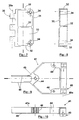
- Part 1 consists of a cylindrical body 10 transversely flattened whose a geometric generator is illustrated with reference 11.
- the body 10 is constituted by a thin wall 12 of thickness E monobloc, that is to say in one piece.
- the wall 12 has four adjacent parts two to two according to a generator 11.
- the first part or hot wall 13 is flat and rectangular.
- the second part or cold wall 14 is flat, rectangular and opposite and parallel to the hot wall 13.
- the third and the fourth part are made by the walls lateral 15 and are convex, that is to say curved outwards.
- the wall 12 is in refractory composite material.
- this material consists of 18 refractory fibers continuous and crossed embedded in a matrix also refractory.
- the radius of curvature R of the inner surface 17 must be at least equal to twice the thickness E of the wall 12 to avoid the stress delamination of the fiber plies 18, that is to say the separation of the different layers by rupture of the matrix.
- the height H of flap is at least equal to six times the thickness E of the wall.
- Such a structure allows thin shutters whose width L1 is at least five times the height H.
- Part of the fibers 18a are globally parallel to each other.
- the fibers 18 are inclined at 45 ° with respect to generators 11.
- This configuration is more particularly used for a short body 12.
- the half of the fibers 18a crosses the other half of the fibers 18b at 90 °.
- the manufacture of the body 10 is made by the techniques well known to those skilled in the art.
- the fiber fabric can be a classic sheet.
- a multilayer fabric for example a so-called "2.5D" fabric disclosed by the US Patent 5,899,241 to Patent Priority French FR 2.759.096.
- the hot wall 13 is licked at least in part by the hot gas stream 4 propulsion while the cold wall 14 opposite the hot wall 13 is licked by a cold stream 5.
- the hot wall 13 expands with respect to the wall cold 14 but the tensile force that is so transmitted to the cold wall 14 transversely to the generators 11 is attenuated by the deformation of side walls 15 which therefore takes up part of this effort.
- Such a component therefore makes it possible to reduce substantially the tensile stresses caused by thermal gradients, which allows the use Refractory composite materials with vitreous rupture such as those mentioned above, which solves the problem.
- the subject of the present invention also the advantage of allowing the reduction of infrared signature of the nozzle in two ways.
- the cold wall 14 is better insulated thermally from the hot wall 13 because of the hollow structure of the shutter.
- Part 1 is equipped upstream 2 with an element upstream articulation joint 30 of the swiveling type integral with a upstream insert 31 consisting of three ribs 32 plus high than wide, of a connecting wall 33 transversely the ribs 32 between them and providing lateral rigidity, and two bosses 34.
- articulation element we mean the part of the joint that remains attached to the shutter when the joint is disassembled.
- the element 30 upstream articulation, the upstream insert 31 and its constituents so defined constitute a whole monobloc, that is to say in one piece.
- the upstream insert 31 is deposited in the inner cavity 16 upstream 2 of the flap 1.
- the upstream insert 31 is disposed in the interior cavity 16 upstream 2 of the shutter 1.
- the insert upstream 31 is held against the cold wall 14 by two screw 35 whose head is outside the shutter 1, these screw 35 passing through the cold wall 14 and coming screw in the bosses 34.
- the cold wall 14 is taken locally sandwiched between the heads of the screws 35 and the insert.
- the screws 35 are advantageously separated so that they are each positioned in the vicinity of a side wall 15 not to impose on the cold wall bending stresses transversely to generators 11, the forces being taken up by the angle formed by the cold wall 14 in the vicinity of the wall side 15 at this location and by this side wall 15.
- Part 1 is also equipped with a downstream articulation member 40 of the pivoting type connected to a downstream insert 41 and forming with it a set piece.
- the downstream articulation element 40 is deported outside the shutter on the side of the cold wall 14.
- the downstream articulation element 40 allows pivoting along a geometric axis 40a perpendicular to generators 11, parallel to the cold wall 14 and substantially in alignment with this cold wall 14.
- Part 1 is also equipped with a clevis connecting rod 42 applied against the cold wall 14 to the outside of the flap 1, the connecting rod cap 42 being located on the middle part of part 1 to equal distance from the side walls 15.
- the downstream insert 41 is extended inside from flap 1 to under the connecting rod yoke 42.
- the insert downstream 41 is fixed against the cold wall 14 by three screw 43 whose head is outside the shutter 1, the screw passing through the cold wall 14 and screwing each in a boss 44 of the downstream insert 41.
- Two three screws 43 are close to the element downstream articulation 40 and spread to be also positioned each in the vicinity of a wall this is for the reasons already stated in the case of the screws 35 fixing the upstream insert 31.
- the third screw 43 also passes through the connecting rod yoke 42 and keeps it against the cold wall. understands that the connecting rod cap 42 allows in exploitation to maneuver the flap 1 by via a rod not shown.
- the downstream insert 41 is also extended upstream 2 by a fork 45 whose branches pass under the connecting rod cap 42 to prevent the cold wall 14 to flex under the force transmitted by the connecting rod clevis 42 to the cold wall 14, the fork 45 resuming this effort.
- the surface of the insert downstream 41 referenced 46 in Figure 9 is in contact with the cold wall 14 and complementary shape, so flat in practice.
- part 1 is extended downstream 3 by a tip 45 which is a extension of the wall 12 and more precisely the hot wall 13 and side walls 15, this extension always according to the generators 11.
- the downstream end 45 allows channel the warm stream 4 further downstream 3 and thus protect the downstream articulation element 40 since the downstream endpiece 45 passes between the articulation element downstream 40 and the hot stream 4.
- the present invention has the advantage in operation of isolating completely the fixing screws 35, 43 of the hot flow 4 since the hot wall 13 passes between the screws and the hot flow, these screws necessarily remaining metallic.
- upstream articulation element 30 which is this time of swivel type according to a geometric axis 30a perpendicular to the generators 11, parallel to the hot and cold walls 13, 14 and at mid-distances from generators 11 defining the hot and cold walls 13, 14.
- This figure also shows the upstream insert 31 introduced into shutter 1 and fixed against the wall cold 14 by the two screws 35.
- downstream tip 45 constituted here by the downstream extension 3 of the downstream insert 41.
- the downstream end 45 is stiffened by ribs 50 planes and perpendicular to the geometric axis of pivoting 40a, the upstream portion of these ribs 50 being drilled according to the geometric axis of pivoting 40a and thus constituting the downstream articulation element 40.
- Stream 1 may have more generally a flattened frustoconical shape, the hot wall 13 and the cold wall 14 then being trapezoidal, of preferably but not necessarily isosceles, the walls lateral 15 being no longer parallel.
- the inserts upstream and downstream 31, 41 can be drilled in order to let a cold air flow through the shutter.
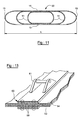
- the walls of the shutter 50 are first materialized by textures composed of the intercrossing of the refractory fibers. These textures here are two in number, one 53 being arranged in the other 54.
- a pair of tensioners is associated with each of the textures 53 and 54 to stretch them to form flat expanses between the profiles, which will give birth to the walls hot and cold.
- Tensioning profiles of the texture 53 have the reference 55, those of the texture 54 the 56.
- the profiles 55 and 56 of each pair are face and have curved sections with convexity directed outward, so that the textures 53, 54 take the form, rounded at least at their edges, of sidewalls 15 and ribs 51.
- the spacing the profile walls 55 and 56 are maintained by spacers 57 of any kind.
- profiles 55 and 56 are perforated or porous, the pores 58.
- the pairs of profiles 55 and 56 are arranged symmetrically to a common plane.
- Textures 53 and 54 thus take on a shape flattened sleeve. They touch each other by their faces planes between the tensioning profiles 55 and 56. It is note that they are formed in practice from sheets of fibers that have been folded and joined by edges opposed.
- the seal lines 59 thus obtained can be sewn or stapled. They can also be pressed between opposite elements of a fitting metal 60 advantageously carrying a clevis 61 of control rod. This is shown in Figure 13. Finally, the seal lines 59 may be adjacent or opposed. Better cohesion can be achieved by sewing or stapling together textures 53 and 54 where they join touch, without this being necessary. In all variants, the material composite is created by depositing the matrix material on the textures 53 and 54 by a deposit in phase of steam.
- the matter of the matrix is slowly entering the fiber network of textures 53 and 54 passing also by the pores 58, which therefore do not allow the tensioning profiles 55 and 56 to weaken the walls 15 and the ribs 51 by stopping the material deposit.
- a hardening of the composite can be achieved by oven heating. The same process is applied to manufacturing flaps without ribs, a single texture and a single wall of tensioning profiles being employed.
- the tensioning profiles 55 and 56 define therefore the shape of the side walls 15 and ribs 51, including rounded edges.
- the superposition of textures on part of the breadth of their portions planes gives a stronger wall thickness hot and cold 13 and 14 in the center. This thickness more large strengthens the flap 50 against bending around the tangential meaning. It has the disadvantage of a deposit more difficult from the matrix material to the heart of the stacking of textures, but that can be obtained by a gradual migration carried out by several stages densification.
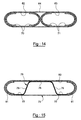
- Tensioners 70 and 71 are used for three textures 62, 63 and 64, the last of which surrounds the other two, who are side by side.
- the profiles 70 extend the texture 62, and the profiles 71 the texture 63.
- the extreme profiles 70 and 71 of the alignment tend also the texture 64, and the two sections 60 and 61 intermediaries, directed towards each other, make touch the inner ends of the textures 62 and 63.
- the same manufacturing process will give a component of nozzle having a central rib particularly strong since it will join the hot and cold walls by pairs of rounded edges.
- the nozzle flap will be formed essentially from a first texture 75, from texture-like shape 54 for example, and a inner texture 76 wavy and with two wings 77 on the sides of the hot wall 13, a strip 78 under the center of the cold wall 14, and two ribs oblique 79 joining the band 78 to the wings 77.
- the internal texture 76 can be stretched and densified partially separately to make it rigid before that the first texture 75 is threaded around her.
- a third texture 80, skirting side walls 15 and the cold wall 14 of a wing 77 to the other, can complete the structure of the component and reinforce the cold wall 14. It can be sewn or the internal texture 76.
- the densification of textures 75, 76 and 80 to form the nozzle flap is then undertaken as for other achievements, with a pair of tensioning profiles 81 at the ends, which are similar to tensioning profiles 56.
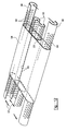
- Figure 16 illustrates a finishing mode of a ribbed nozzle flap, that of FIG. example, where we proceed to the finishing of the pieces of mechanical connection.
- the upstream insert 82 engaged in the shutter proper is fork-shaped and comprises a central tooth 83 engaged between the two ribs 51 and two lateral teeth 84 engaged between the ribs 51 and the side walls 15, and between them. It is completed by a plate 85 which encloses the cold wall 14 between it and the teeth 83 and 84. All these elements are provided with holes 86 of passage of unrepresented clamping screws, which ensure the tightening.
- the nozzle flaps may include radii of curvature more or less important in the limit shown here. Small radii of curvature are in general preferred.
- the sealing flaps 20 cover a smaller width of the hot wall 13 if the side walls 15 have small rounds of connection, and the thermal gradients of the wall hot 13 are reduced; and the nozzle flaps can come closer to each other in the state of closing of the nozzle since they are less wide: a bigger closure becomes possible.
- a particular arrangement of the shutters of nozzle comprises metal parts attached to the cold wall 14 and constructed of titanium. This metal is appreciated for its lightness in aeronautics and elsewhere, but it does not withstand heating well. It is however possible to obtain differences of temperature of 400 ° C between the hot and cold walls 13 and 14 (at 1000 ° C and 600 ° C for example) with the invention, which justifies its use for the fitting 60, the screed 61, etc.
Abstract
Description
L'invention se rapporte aux volets de tuyère pour turbomoteurs d'avion et plus particulièrement à des volets en matériau composite réfractaire.The invention relates to the shutters of nozzle for aircraft turboshaft engines and more particularly to components made of composite material refractory.
Les tuyères à section variable sont bien connues dans l'aéronautique pour canaliser le flux des gaz de propulsion en fonction du régime des turbomoteurs qui les produisent. Dans ce qui suit, les tuyères à section variable seront simplement appelées « tuyères ».Variable section nozzles are well known in aeronautics to channel the flow of propulsion gas according to the regime of turboshaft engines that produce them. In the following, the nozzles with variable section will simply be called "Nozzles".
Le brevet US 5 285 637 présente clairement un modèle élaboré de tuyère comportant successivement de l'avant vers l'arrière un tronçon convergeant et un tronçon divergeant, cette tuyère étant également susceptible d'une poussée dite « vectorielle » obtenue par déviation du flux de gaz de propulsion. Il existe des tuyères plus simples qui sont limitées à un seul tronçon convergeant et/ou qui sont axisymétriques, c'est-à-dire qu'elles ne permettent pas de dévier le flux de gaz de propulsion. Dans tous les cas, une tuyère comporte une pluralité de volets jointifs pour former un canal à section variable autour des gaz de propulsion. Un volet a une structure générale de plaque rectangulaire mince et allongée et il est articulé à l'élément mécanique situé juste en amont de lui. Le volet peut dans certains cas particuliers être de forme trapézoïdale généralement isocèle, la forme rectangulaire en constituant la forme limite. Dans le cas d'une tuyère convergente et divergente, chaque volet du tronçon convergent est ainsi articulé en amont à la structure fixe mais également en aval au volet du tronçon divergent qui est dans son prolongement. La face dite « intérieure » du volet, c'est-à-dire tournée vers l'intérieur de la tuyère, est léchée directement en tout ou en partie par le flux de gaz chaud de propulsion désigné ci-après « flux chaud ». Au contraire, la face opposée dite « extérieure », c'est-à-dire tournée vers l'extérieur de la tuyère, est léchée en tout ou en partie par un flux de l'air froid désigné ci-après « flux froid ».US Pat. No. 5,285,637 clearly discloses an elaborate model of nozzle comprising successively from front to back a converging stretch and a diverging section, this nozzle being also susceptible to a so-called "vector" push by deflection of the propulsion gas flow. It exists simpler nozzles that are limited to a single converging section and / or which are axisymmetric, that is, they do not allow the deviation propulsion gas flow. In all cases, a nozzle comprises a plurality of contiguous flaps for to form a channel of variable section around the gases of propulsion. A shutter has a general plate structure rectangular thin and elongated and it is articulated to the mechanical element located just upstream of it. The shutter can in some particular cases be of form trapezoidal generally isosceles, the shape rectangular in constituting the limit form. In the the case of a convergent and divergent nozzle, each component of the convergent section is thus articulated upstream to the fixed structure but also downstream to the divergent section that is in its extension. The so-called "inner" side of the shutter, ie turned towards the inside of the nozzle, is licked directly in whole or in part by the flow of hot gas from propulsion hereinafter referred to as "hot flow". At contrary, the so-called "outer" opposite face, that is to say turned towards the outside of the nozzle, is licked in whole or in part by a flow of cold air hereinafter referred to as "cold flow".
On distingue les volets dits « commandés » et les volets dits « d'étanchéité ». Les volets commandés sont reliés à des biellettes qui les rapprochent ou qui les éloignent de l'axe géométrique de la tuyère afin d'en faire varier la section. Les espaces de largeur variable entre les volets commandés sont occultés par les volets d'étanchéité qui sont situés entre les volets commandés et le flux de gaz de propulsion, ces volets d'étanchéité étant maintenus plaqués contre les volets commandés par des moyens mécaniques et par la pression des gaz de propulsion. On comprend que les volets commandés subissent de fortes sollicitations mécaniques. En exploitation, la surface des volets exposée au flux chaud est couramment portée à des températures de l'ordre de 1000°C. De ce fait, les volets de tuyère sont habituellement en alliage métallique réfractaire, c'est-à-dire résistant aux hautes températures. Malgré cela, leur durée de vie reste limitée.We distinguish so-called "controlled" shutters and so-called "sealing shutters". Shutters ordered are connected to rods which move them closer to or away from the geometric axis of the nozzle in order to vary the section. The spaces of variable width between the shutters ordered are obscured by the sealing flaps that are located between the shutters ordered and the gas flow of propulsion, these sealing flaps being maintained pressed against shutters controlled by means mechanical and by the pressure of the propulsion gases. We understands that the shutters ordered undergo strong mechanical stresses. In operation, the surface flaps exposed to the hot flow is commonly worn at temperatures of the order of 1000 ° C. Thereby, the nozzle flaps are usually made of alloy refractory metal, that is to say, resistant to high temperatures. Despite this, their lifespan remains limited.
Certaines solutions proposées, comme dans le document US 2 770 944, impliquent une construction à double paroi des volets de tuyère. Les inconvénients précédents demeurent pour l'essentiel ; la construction à double paroi est en général exploitée pour faire circuler de l'air de refroidissement à travers leur intervalle, mais des différences importantes de température demeurent dans le volet malgré le rafraíchissement obtenu.Some proposed solutions, as in US 2,770,944, imply a construction to double wall of the nozzle flaps. The inconvenients precedents remain for the most part; construction double wall is generally used to circulating cooling air through their interval but significant differences in temperature remain in the shutter despite the refreshment obtained.
On connaít des matériaux composites réfractaires constitués de fibres réfractaires noyées dans une matrice réfractaire. Les fibres et la matrice peuvent être du carbone. Les fibres et la matrice peuvent être également de la céramique telle le carbure de silicium SiC, les aluminures de titane, les aluminures d'aluminium, etc. Malgré leur résistance mécanique et leur résistance en température élevée, de tels matériaux se prêtent mal à la constitution de volets de tuyères car ils sont très vulnérables aux gradients thermiques générateurs de contraintes en traction du fait de leur rupture du type « vitreuse ». Par rupture « vitreuse », on entend que le matériau se rompt brutalement sous l'effet d'une contrainte en traction dès que cette contrainte dépasse la limite élastique du matériau. Cette vulnérabilité est aggravée avec les matériaux composites réfractaires qui ont un module d'élasticité ou module de Young élevé et se maintenant aux hautes températures.Composite materials are known refractory consisting of embedded refractory fibers in a refractory matrix. Fibers and matrix can be carbon. Fibers and matrix can also be ceramic such as carbide SiC silicon, titanium aluminides, aluminides of aluminum, etc. Despite their resistance mechanics and their high temperature resistance, Such materials do not lend themselves well to the constitution of shutters of nozzles because they are very vulnerable to thermal gradients generating constraints in traction because of their rupture of the type "vitreous". By "vitreous" rupture, we mean that the material is breaks suddenly under the effect of a constraint traction as soon as this constraint exceeds the limit elastic material. This vulnerability is aggravated with refractory composite materials that have a modulus of elasticity or modulus of Young high and now at high temperatures.
On a tenté de réaliser des volets en matériau composite réfractaire se présentant sous la forme de plaques rectangulaires allongées planes et minces sur lesquels sont fixés des éléments de liaison en alliage métallique réfractaire. Avec de tels volets, la face froide tend à se fissurer sous l'effet des différences de température entre la face chaude et la face froide, la dilatation de la face chaude générant des contraintes de traction sur la face froide. Dans le cas des volets commandés, la température au centre du volet est plus élevée que vers ses bords latéraux car le centre du volet est directement exposé au flux chaud alors que les bords latéraux sont isolés du flux chaud par les volets d'étanchéité. De ce fait, la dilatation du volet au centre génère sur les bords des contraintes de traction qui provoquent des fissurations tendant à se propager vers le centre et à rompre le volet.We tried to realize refractory composite material in the form of form of elongated flat rectangular plates and thin plates on which connecting elements are attached in refractory metal alloy. With such shutters, the cold side tends to crack under the effect of temperature differences between the hot face and the cold face, the dilation of the hot face generating tensile stresses on the cold face. In the shutters ordered, the temperature in the center of the flap is higher than towards its side edges because the center of the shutter is directly exposed to the hot flow while the side edges are isolated from the hot stream by the sealing flaps. As a result, dilatation of the shutter at the center generates constraints on the edges traction causing cracks tending to spread to the center and break the shutter.
Il ressort que, comme les matériaux composites réfractaires sont vulnérables aux gradients thermiques et que ceux-ci sont inévitables dans les volets de tuyère, les tentatives de construire ces pièces en ces matériaux ne semblent pas avoir bien réussi. Le problème affronté par les inventeurs était donc de construire des volets de tuyère en matériaux composites réfractaires dont la durée de vie serait réellement accrue. It appears that, like the materials refractory composites are vulnerable to gradients thermals and that these are inevitable in nozzle flaps, attempts to build these pieces made of these materials do not seem to have well successful. The problem faced by the inventors was therefore to build nozzle flaps made of materials refractory composites whose lifetime would be really increased.
Pour résoudre ce problème, l'invention propose un volet de tuyère remarquable en ce qu'il est constitué d'un corps tronconique creux et transversalement aplati suivant des génératrices géométriques rectilignes, le corps formant une paroi mince d'épaisseur sensiblement constante E, cette paroi étant divisée transversalement en quatre parties adjacentes soit : une paroi trapézoïdale et plane dite « chaude », une paroi trapézoïdale et plane dite « froide » parallèle à la paroi chaude et deux parois latérales symétriques reliant latéralement la paroi froide et la paroi chaude, la paroi comportant une surface intérieure continue avec un rayon de courbure au moins égal à 2xE, la paroi étant en matériau composite réfractaire constitué de fibres de renfort continues et croisées en matériau réfractaire noyées dans une matrice en matériau également réfractaire.To solve this problem, the invention proposes a remarkable nozzle flap in that it is consisting of a hollow frustoconical body and transversely flattened following generators rectilinear geometries, the body forming a wall thin of substantially constant thickness E, this wall being divided transversely into four parts adjacent to: a so-called trapezoidal and flat wall "Hot", a so-called trapezoidal and flat wall "Cold" parallel to the hot wall and two walls symmetrical sides laterally connecting the wall cold and the hot wall, the wall having a continuous inner surface with a radius of curvature at least equal to 2xE, the wall being of material refractory composite made of reinforcing fibers continuous and cross drowned refractory material in a matrix of material also refractory.
Des volets de tuyère à double paroi en matière composite ne semblent pas avoir été proposés dans l'art. Les raisons sont probablement à rechercher en raison de la constatation que les gradients de température y existent aussi et que les risques de rupture vitreuse ne sont point diminués ; et en la difficulté de façonner un tel volet de tuyère avec les techniques spécifiques aux matériaux composites.Double-walled nozzle shutters made of composite material do not seem to have been proposed in art. The reasons are probably to search because of the finding that the gradients of temperature also exist and that the risks of vitreous rupture are not diminished; and in difficulty of shaping such a nozzle flap with the techniques specific to composite materials.
Il est cependant apparu que la présence de parois latérales se raccordant aux bords de la paroi chaude par des bords arrondis changeait complètement la tenue du volet aux sollicitations d'origine thermique. However, it appeared that the presence of side walls connecting to the edges of the wall hot by rounded edges completely changed the holding of the shutter with the stresses of thermal origin.
Une résistance satisfaisante à la rupture vitreuse est espérée avec les volets conforme à l'invention. De plus, la mauvaise conductivité thermique des matériaux composites réduit les transfert de chaleur vers la paroi froide, sans qu'un refroidissement par circulation d'air entre les parois soit nécessaire ni même probablement favorable puisqu'il pourrait accroítre les différences de températures dans la paroi chaude d'une face à l'autre.Satisfactory resistance to fracture vitreous is expected with the shutters according to the invention. In addition, poor conductivity Thermal composite materials reduces transfer of heat towards the cold wall, without cooling by circulation of air between the walls is necessary or even probably favorable since it could increase the differences of temperatures in the hot wall from one face to another.
Dans un mode particulier de réalisation, ce volet comporte à une extrémité un élément d'articulaire dit « amont » solidaire d'un insert dit « amont » pénétrant dans la cavité du volet, l'insert étant tenu par des vis contre la paroi froide, la paroi froide étant prise localement en sandwich entre les têtes des vis et l'insert amont, les vis traversant la paroi froide et se vissant dans l'insert amont.In a particular embodiment, this shutter has at one end an articular element said "upstream" attached to an insert called "upstream" penetrating into the cavity of the shutter, the insert being held by screws against the cold wall, the cold wall being taken locally sandwiched between the heads of screw and the upstream insert, the screws passing through the wall cold and screwing into the upstream insert.
Dans un autre mode de réalisation n'excluant pas le premier, le volet comporte un élément d'articulation dit « aval » solidaire d'un insert dit « aval » et une chape de bielle appliquée contre la paroi froide à l'extérieur du volet, la chape de bielle étant située sur la partie médiane du volet, l'insert aval se prolongeant à l'intérieur du volet jusque sous la chape de bielle, l'insert aval étant fixé contre la paroi froide par au moins trois vis dont la tête est à l'extérieur du volet, les vis traversant la paroi froide et venant se visser dans l'insert aval, l'une des trois vis traversant également la chape de bielle et permettant de la maintenir contre la paroi froide. In another embodiment does not exclude the first, the component has an element articulation said "downstream" integral with an insert said "Downstream" and a connecting rod clevis applied against the cold wall outside the flap, the connecting rod being located on the middle part of the shutter, the insert downstream extending inside the flap until under the end cap, the downstream insert being fixed against the cold wall by at least three screws whose head is at the outside of the shutter, the screws passing through the wall cold and coming to screw into the downstream insert, one three screws also passing through the connecting rod and to keep it against the cold wall.
L'isolation thermique offerte par le volet dépend aussi de son épaisseur, c'est-à-dire de la largeur des parois latérales. Il est avantageux que celles-ci ne comprennent pas seulement des portions arrondies mais aussi des portions planes pour offrir une barrière plus grande aux échauffements.The thermal insulation offered by the shutter also depends on its thickness, that is to say the width of the side walls. It is advantageous that these do not just include portions rounded but also flat portions to offer a greater barrier to overheating.
La résistance mécanique du volet doit parfois être renforcée. Le volet comprendra alors des nervures joignant les parois trapézoïdales et planes par des portions arrondies ayant un rayon de courbure au moins égal à 2xE. Ces nervures sont aussi en matière composite réfractaire et ne sont responsables que d'une faible fuite de chaleur vers la paroi froide.The mechanical strength of the shutter must sometimes be strengthened. The component will then include ribs joining the trapezoidal and flat walls by rounded portions having a radius of curvature at least equal to 2xE. These ribs are also in matter refractory composite and are only responsible for a low heat leakage to the cold wall.
Un aspect important de l'invention est le procédé de fabrication d'un tel volet de tuyère. Il comprend les étapes de création d'une texture à bords continus de fibres réfractaires entrecroisées, de mise en tension de la texture autour de profilés rigides et poreux, opposés et incurvés avec des convexités dirigées dans des directions divergentes et ayant des rayons de courbure au moins égaux à 2xE, E étant l'épaisseur de la texture, et de dépôt d'une matrice réfractaire par dépôt en phase de vapeur sur la texture et à travers les profilés.An important aspect of the invention is the method of manufacturing such a nozzle flap. he includes the steps to create an edged texture continuous interwoven refractory fibers, in tension of the texture around rigid sections and porous, opposite and curved with convexities directed in divergent directions and having radius of curvature at least equal to 2xE, E being the thickness of the texture, and deposition of a matrix refractory by vapor phase deposition on the texture and through the profiles.
Une variante de ce procédé, utilisée pour construire un volet nervuré dont nous avons parlé ci-dessus, comprend les étapes de création d'une pluralité de textures à bords continus de fibres réfractaires entrecroisées, de mise en tension des textures autour de paires de profilés rigides et poreux, opposés et incurvés avec des convexités dirigées dans des directions divergentes pour chacune des parois, les profilés ayant respectivement des rayons de courbure au moins égaux à 2xE, E étant l'épaisseur d'une des textures qui est tendue sur le profilé, et de dépôt d'une matrice réfractaire par dépôt en phase de vapeur sur les textures et à travers les profilés, les textures ayant des portions superposées et la matrice étant continue à travers lesdits portions superposées.A variant of this process, used for build a ribbed flap that we talked about above, includes the steps of creating a plurality textures with continuous edges of refractory fibers intertwined, tensioning textures around pairs of rigid and porous profiles, opposed and curved with convexities directed into divergent directions for each of the walls, the profiles respectively having radii of curvature at less than 2xE, where E is the thickness of one of the textures that is stretched over the profile, and deposition of a refractory matrix by vapor phase deposition on the textures and through the profiles, the textures with superimposed portions and the matrix being continuous through said superimposed portions.
L'invention sera mieux comprise et les
avantages qu'elle procure apparaítront plus clairement
au vu d'exemples détaillés de réalisation et des
figures annexées.
On se reportera en premier lieu
simultanément aux figures 1 et 2. Le volet de tuyère 1
est léché de l'amont 2 vers l'aval 3 d'un côté par un
flux de gaz de propulsion chaud 4 et de l'autre coté
par un flux de gaz froid. Le volet 1 est constitué par
un corps 10 cylindrique transversalement aplati dont
une génératrice géométrique est illustrée en référence
11. Le corps 10 est constitué par une paroi 12 mince
d'épaisseur E monobloc, c'est-à-dire en un seul tenant.
La paroi 12 comporte quatre parties adjacentes deux à
deux selon une génératrice 11. La première partie ou
paroi chaude 13 est plane et rectangulaire. La seconde
partie ou paroi froide 14 est plane, rectangulaire et
opposée et parallèle à la paroi chaude 13. La troisième
et la quatrième partie sont constituées par les parois
latérales 15 et sont convexes, c'est-à-dire bombées
vers l'extérieur. On référencera 16 la cavité
intérieure formée par la paroi 12 et 17 la surface
intérieure de cette paroi 12. La paroi 12 est en
matériau composite réfractaire. A cet effet, ce
matériau est constitué de fibres 18 réfractaires
continues et croisées noyées dans une matrice également
réfractaire. Avec un tel matériau, le rayon de courbure
R de la surface intérieure 17 doit être au moins égal à
deux fois l'épaisseur E de la paroi 12 afin d'éviter le
délaminage sous contrainte des nappes de fibres 18,
c'est-à-dire la séparation des différentes nappes par
rupture de la matrice. En conséquence, la hauteur H du
volet est au moins égale à six fois l'épaisseur E de la
paroi. Une telle structure autorise des volets minces
dont la largeur L1 est au moins égale à cinq fois la
hauteur H.We will refer first
simultaneously with Figures 1 and 2. The nozzle flap 1
is licked from upstream 2 downstream 3 on one side by a
flow of hot propellant gas 4 and on the other side
by a flow of cold gas. Part 1 consists of
a
Une partie des fibres 18a sont globalement
parallèles entre elles. Dans cet exemple, les fibres 18
sont inclinées à 45° par rapport aux génératrices 11.
Cette configuration est plus particulièrement utilisée
pour un corps 12 court. Dans le cas d'un corps 12 long,
on préférera disposer une partie des fibres 18a
parallèlement aux génératrices 11 et l'autre partie des
fibres 18b perpendiculairement aux génératrices 18b
afin d'améliorer la résistance en flexion. Dans tous
les cas, un nombre suffisant de nappes doivent
comporter des fibres 18 entourant le corps 10
transversalement aux génératrices 11. En pratique, la
moitié des fibres 18a croise l'autre moitié des fibres
18b à 90°. La fabrication du corps 10 est faite par les
techniques bien connues de l'homme du métier. La mise
en place des fibres peut se faire par bobinage croisé
des fibres sur un mandrin ou par application d'un tissu
de fibres peu serrées. Le tissu de fibres peut être un
drap classique. Pour améliorer la résistance du volet,
on peut avantageusement utiliser un tissu multicouche,
par exemple un tissu dit « 2,5D » divulgué par le
brevet américain US 5 899 241 à priorité du brevet
français FR 2.759.096.Part of the fibers 18a are globally
parallel to each other. In this example, the fibers 18
are inclined at 45 ° with respect to
On se reportera plus particulièrement à la
figure 2. En exploitation, la paroi chaude 13 est
léchée au moins en partie par le flux chaud 4 de gaz de
propulsion alors que la paroi froide 14 opposée à la
paroi chaude 13 est léchée par un flux froid 5. La
paroi chaude 13 se dilate donc par rapport à la paroi
froide 14, mais l'effort de traction qui est ainsi
transmis à la paroi froide 14 transversalement aux
génératrices 11 est atténué par la déformation des
parois latérales 15 qui reprend donc une partie de cet
effort.We will particularly refer to the
figure 2. In operation, the
Dans cet exemple, on a représenté deux
volets d'étanchéité 20 qui arrivent au contact de la
paroi chaude 13 dans le voisinage des parois latérales
15. Ainsi, les zones de contact 21 de la paroi chaude
13 avec les volets d'étanchéité 20 ainsi que les parois
latérales 15 ne sont pas léchées par le flux chaud 4 et
sont donc ainsi plus froides. Toutefois, au contraire
d'une simple plaque, les contraintes de traction dans
le sens des génératrices 11 imposées à la paroi chaude
dans les zones de contact 21 sont réduites par la
présence des parois latérales 15 qui s'opposent à cette
dilatation et reprennent donc une partie de l'effort de
traction produit. En d'autres termes, les contraintes
de traction se répartissent dans les zones de contact
21 et dans les parois latérales 15, ce qui en réduit la
valeur maximale.In this example, there are two
sealing
Un tel volet permet donc de réduire sensiblement les contraintes de traction provoquées par les gradients thermiques, ce qui autorise l'utilisation de matériaux composites réfractaires à rupture vitreuse tels que ceux précités, ce qui résout le problème posé.Such a component therefore makes it possible to reduce substantially the tensile stresses caused by thermal gradients, which allows the use Refractory composite materials with vitreous rupture such as those mentioned above, which solves the problem.
Le volet objet de l'invention présente
l'avantage d'être plus léger que son équivalent se
présentant sous la forme d'une plaque en matériau
composite réfractaire. En effet, un volet constitué
d'une plaque pleine de 7mm peut être remplacé par un
volet selon l'invention dont la paroi ne fait que 2mm
d'épaisseur, ceci pour une résistance en flexion dix
fois supérieure, l'épaisseur cumulée de la paroi chaude
14 et de la paroi froide 15 étant donc de 2mm+2mm=4mm.The subject of the present invention
the advantage of being lighter than its equivalent
presenting in the form of a plate of material
refractory composite. Indeed, a component
of a solid plate of 7mm can be replaced by a
shutter according to the invention whose wall is only 2mm
thick, this for ten flexural strength
times greater, the cumulative thickness of the
Le volet objet de l'invention présente
aussi l'avantage de permettre la réduction de la
signature infrarouge de la tuyère de deux manières. En
effet, la paroi froide 14 est mieux isolée
thermiquement de la paroi chaude 13 du fait de la
structure creuse du volet.The subject of the present invention
also the advantage of allowing the reduction of
infrared signature of the nozzle in two ways. In
indeed, the
On se reportera de nouveau à la figure 1.
Le volet 1 est équipé vers l'amont 2 d'un élément
d'articulation amont 30 du type rotulant solidaire d'un
insert amont 31 constitué de trois nervures 32 plus
hautes que larges, d'une paroi 33 reliant
transversalement les nervures 32 entre elles et
assurant une rigidité latérale, et de deux bossages 34.
Par élément d'articulation, on entend la partie de
l'articulation qui reste solidaire du volet lorsque
l'articulation est désassemblée. L'élément
d'articulation amont 30, l'insert amont 31 et ses
constituants ainsi définis constituent un ensemble
monobloc, c'est-à-dire d'un seul tenant. L'insert amont
31 est déposé dans la cavité intérieure 16 en amont 2
du volet 1. L'insert amont 31 est disposé dans la
cavité intérieure 16 en amont 2 du volet 1. L'insert
amont 31 est tenu contre la paroi froide 14 par deux
vis 35 dont la tête est à l'extérieur du volet 1, ces
vis 35 traversant la paroi froide 14 et venant se
visser dans les bossages 34. En d'autres termes, la
paroi froide 14 est prise localement en sandwich entre
les têtes des vis 35 et l'insert. Les vis 35 sont
avantageusement écartées de façon à ce qu'elles soient
chacune positionnées au voisinage d'une paroi latérale
15 afin de ne pas imposer à la paroi froide des
contraintes de flexion transversalement aux
génératrices 11, les efforts étant repris par l'angle
formé par la paroi froide 14 au voisinage de la paroi
latérale 15 à cet endroit et par cette paroi latérale
15.Reference is again made to Figure 1.
Part 1 is equipped upstream 2 with an element
upstream articulation joint 30 of the swiveling type integral with a
Le volet 1 est également équipé d'un
élément d'articulation aval 40 du type pivotant relié à
un insert aval 41 et formant avec lui un ensemble
monobloc. L'élément d'articulation aval 40 est déporté
à l'extérieur du volet du côté de la paroi froide 14.
L'élément d'articulation aval 40 permet un pivotement
selon un axe géométrique 40a perpendiculaire aux
génératrices 11, parallèle à la paroi froide 14 et
sensiblement dans l'alignement de cette paroi froide
14. Le volet 1 est également équipé d'une chape de
bielle 42 appliquée contre la paroi froide 14 à
l'extérieur du volet 1, la chape de bielle 42 étant
située sur la partie médiane du volet 1 à égale
distance des parois latérales 15.Part 1 is also equipped with a
L'insert aval 41 se prolonge à l'intérieur
du volet 1 jusque sous la chape de bielle 42. L'insert
aval 41 est fixé contre la paroi froide 14 par trois
vis 43 dont la tête est à l'extérieur du volet 1, les
vis traversant la paroi froide 14 et venant se visser
chacune dans un bossage 44 de l'insert aval 41. Deux
des trois vis 43 sont proches de l'élément
d'articulation aval 40 et écartées pour être
positionnées également chacune au voisinage d'une paroi
latérale, ceci pour les raisons déjà énoncées dans le
cas des vis 35 fixant l'insert amont 31. La troisième
vis 43 traverse également la chape de bielle 42 et
permet de la maintenir contre la paroi froide 14. On
comprend que la chape de bielle 42 permet en
exploitation de manoeuvrer le volet 1 par
l'intermédiaire d'une bielle non représentée.The
L'insert aval 41 est également prolongé
vers l'amont 2 par une fourche 45 dont les branches
passent sous la chape de bielle 42 afin d'empêcher la
paroi froide 14 de fléchir sous l'effort transmis par
la chape de bielle 42 à la paroi froide 14, la fourche
45 reprenant ainsi cet effort. La surface de l'insert
aval 41 référencée 46 sur la figure 9 est au contact de
la paroi froide 14 et de forme complémentaire, donc
plane en pratique.The
Dans cet exemple également, le volet 1 est
prolongé vers l'aval 3 par un embout 45 qui est un
prolongement de la paroi 12 et plus précisément de la
paroi chaude 13 et des parois latérales 15, ce
prolongement se faisant toujours selon la génératrices
11. En exploitation, l'embout aval 45 permet de
canaliser le flux chaud 4 plus loin vers l'aval 3 et de
protéger ainsi l'élément d'articulation aval 40 puisque
l'embout aval 45 passe entre l'élément d'articulation
aval 40 et le flux chaud 4. La présente invention
présente l'avantage en exploitation d'isoler
complètement les vis de fixation 35, 43 du flux chaud 4
puisque la paroi chaude 13 passe entre les vis et le
flux chaud, ces vis restant nécessairement métalliques.
On se reportera à la figure 3 pour voir un exemple
d'élément d'articulation amont 30 qui est cette fois de
type pivotant selon un axe géométrique 30a
perpendiculaire aux génératrices 11, parallèle aux
parois chaude et froide 13, 14 et à mi-distances des
génératrices 11 définissant les parois chaude et froide
13, 14. Cette figure montre également l'insert amont 31
introduit dans le volet 1 et fixé contre la paroi
froide 14 par les deux vis 35.In this example too, part 1 is
extended downstream 3 by a
On se reportera à la figure 4 pour voir un
exemple d'embout aval 45 constitué ici par le
prolongement vers l'aval 3 de l'insert aval 41.
L'embout aval 45 est rigidifié par des nervures 50
planes et perpendiculaires à l'axe géométrique de
pivotement 40a, la partie amont de ces nervures 50
étant percées selon l'axe géométrique de pivotement 40a
et constituant ainsi l'élément d'articulation aval 40.We will refer to Figure 4 to see a
example of
On se reportera aux figures 5 et 6 pour
voir plus précisément la constitution de l'élément
d'articulation 30 de type rotulant et l'insert amont
31. On se reportera aux figures 7 et 8 pour voir ces
mêmes constituants dans le cas d'un élément
d'articulation 30 de type pivotant selon l'axe
géométrique 30a.Refer to Figures 5 and 6 for
see more precisely the constitution of the element
articulating joint 30 and the
On se reportera enfin aux figures 9 et 10
pour voir plus précisément l'insert aval 41 et
l'élément d'articulation aval 40. Dans certaines
utilisations, le volet 1 peut avoir plus généralement
une forme tronconique aplatie, la paroi chaude 13 et la
paroi froide 14 étant alors trapézoïdales, de
préférence mais non obligatoirement isocèle, les parois
latérales 15 n'étant plus alors parallèles. Les inserts
amont et aval 31, 41 peuvent être percés afin de
laisser passer un flux d'air froid à l'intérieur du
volet.Finally, see Figures 9 and 10
to see more precisely the
Le volet 1 tel qu'il a été décrit jusqu'ici
présente cependant certains inconvénients liés à la
grande extension latérale de la paroi froide 14 et
surtout de la paroi chaude 13. La pression des gaz à
laquelle cette dernière est soumise peut produire à la
fois des déformations qui accroissent les contraintes
de flexion et de cisaillement interlaminaire aux bords
arrondis de la paroi chaude 13, ainsi que des
vibrations. Le volet de tuyère illustré à la figure 11
permet de lutter contre ces inconvénients. Il porte la
référence 50 et se distingue du précédent par la
présence de nervures 51 joignant la paroi froide 14 à
la paroi chaude 13 entre les parois latérales 15. Les
nervures 51 sont ici au nombre de quatre. Leur
direction d'allongement est essentiellement la même que
celle des parois latérales 15. Elles sont aussi
construites comme les parois latérales 15, avec des
bords arrondis 52 ayant un rayon de courbure intérieur
au moins deux fois supérieur à l'épaisseur. Ici encore
des contraintes intolérables sont évitées aux jonctions
à la paroi chaude 13.Stream 1 as described so far
However, there are some disadvantages
large lateral extension of the
Le mode de fabrication d'un tel volet de
tuyère est détaillé au moyen de la figure 12 pour un
volet ne présentant qu'une paire de nervures 51 ; cette
configuration plus simple a été choisie pour ne pas
compliquer excessivement le dessin, mais il sera
évident d'appliquer le procédé à la réalisation de la
figure 11 ou à d'autres réalisations décrites ensuite.The method of manufacturing such a component of
nozzle is detailed by means of FIG.
shutter having only one pair of
Les parois du volet 50 sont d'abord
matérialisées par des textures composées de
l'entrecroisement des fibres réfractaires. Ces textures
sont ici au nombre de deux, l'une 53 étant disposée
dans l'autre 54. De plus, une paire de profilés
tendeurs est associée à chacune des textures 53 et 54
pour les tendre de façon à former des étendues planes
entre les profilés, qui donneront naissance aux parois
chaude et froide. Les profilés tendeurs de la texture
53 ont la référence 55, ceux de la texture 54 la
référence 56. Les profilés 55 et 56 de chaque paire se
font face et ont des sections incurvées à la convexité
dirigée vers l'extérieur, afin que les textures 53, 54
prennent la forme, arrondie au moins à leurs bords, des
parois latérales 15 et des nervures 51. L'écartement
les parois de profilés 55 et 56 est maintenu par des
entretoises 57 d'une nature quelconque. Enfin, les
profilés 55 et 56 sont ajourés ou poreux, les pores portant
les références 58. Les paires de profilés 55 et 56 sont
disposés symétriquement à un plan commun.The walls of the
Les textures 53 et 54 prennent donc une forme
de manchon aplati. Elles se touchent par leurs faces
planes entre les profilés tendeurs 55 et 56. Il est à
noter qu'elles sont formées en pratique de feuilles de
fibres qu'on a repliées et jointes par des bords
opposés. Les lignes de joint 59 ainsi obtenues peuvent
être cousues ou agrafées. Elles peuvent aussi être
pressées entre des éléments opposés d'une ferrure
métallique 60 portant avantageusement une chape 61 de
bielle de commande. Cela est représenté à la figure 13.
Enfin, les lignes de joint 59 peuvent être voisines ou
opposées. Une meilleure cohésion pourra être obtenue en
cousant ou agrafant ensemble les textures 53 et 54 où
elles se joignent touchent, sans que cela soit
nécessaire. Dans toutes les variantes, le matériau
composite est créé en déposant la matière de matrice
sur les textures 53 et 54 par un dépôt en phase de
vapeur. La matière de la matrice pénètre peu à peu dans
le réseau des fibres des textures 53 et 54 en passant
aussi par les pores 58, qui ne permettent donc pas aux
profilés tendeurs 55 et 56 d'affaiblir les parois
latérales 15 et les nervures 51 en arrêtant la matière
de dépôt. Après cette étape de densification, un
durcissement du composite peut être réalisé par
chauffage au four. Le même procédé est appliqué à la
fabrication des volets sans nervures, une seule texture
et une seule paroi de profilés tendeurs étant employés.
Les profilés tendeurs 55 et 56 définissent
donc la forme des parois latérales 15 et des nervures
51, y compris aux bords arrondis. La superposition des
textures sur une partie de l'étendue de leurs portions
planes donne une épaisseur plus forte des parois chaude
et froide 13 et 14 au centre. Cette épaisseur plus
grande renforce le volet 50 contre la flexion autour du
sens tangentiel. Elle a pour inconvénient un dépôt plus
difficile de la matière de la matrice au coeur de
l'empilement des textures, mais qu'on peut obtenir par
une migration progressive réalisée par plusieurs étapes
de densification.The tensioning profiles 55 and 56 define
therefore the shape of the
Une autre configuration encore est décrite
au moyen de la figure 14. Deux paires de profilés
tendeurs 70 et 71 sont utilisées pour trois textures
62, 63 et 64 dont la dernière entoure les deux autres,
qui sont côte à côte. Les profilés 70 étendent la
texture 62, et les profilés 71 la texture 63. De plus,
les profilés 70 et 71 extrêmes de l'alignement tendent
aussi la texture 64, et les deux profilés 60 et 61
intermédiaires, dirigés l'un vers l'autre, font se
toucher les extrémités intérieures des textures 62 et
63. Le même procédé de fabrication donnera un volet de
tuyère ayant une nervure centrale particulièrement
forte puisqu'elle joindra les parois chaude et froide
par des paires de bords arrondis.Another configuration is described
by means of Figure 14. Two pairs of profiles
Tensioners 70 and 71 are used for three
Un autre genre de réalisation apparaít à la
figure 15 : le volet de tuyère sera formé
essentiellement à partir d'une première texture 75, de
forme analogue à la texture 54 par exemple, et d'une
texture interne 76 ondulée et présentant deux ailes 77
sur les côtés de la paroi chaude 13, une bande 78 sous
le centre de la paroi froide 14, et deux nervures
obliques 79 joingnant la bande 78 aux ailes 77. La
texture interne 76 peut être tendue et densifiée
partiellement séparément pour la rendre rigide avant
que la première texture 75 ne soit enfilée autour
d'elle.Another kind of realization appears at the
figure 15: the nozzle flap will be formed
essentially from a
Une troisième texture 80, longeant les
parois latérales 15 et la paroi froide 14 d'une aile 77
à l'autre, peut compléter la structure du volet et
renforcer la paroi froide 14. Elle peut être cousue ou
non à la texture interne 76. La densification des
textures 75, 76 et 80 pour former le volet de tuyère
est alors entreprise comme pour les autres réalisation,
avec une paire de profilés tendeurs 81 aux extrémités,
qui sont semblables aux profilés tendeurs 56.A
La figure 16 illustre un mode de finition
d'un volet de tuyère nervuré, celui de la figure 12 par
exemple, où on procède à la finition des pièces de
liaison mécaniques. L'insert amont 82 engagé dans le
volet proprement dit est en forme de fourchette et
comprend une dent centrale 83 engagée entre les deux
nervures 51 et deux dents latérales 84 engagées entre
les nervures 51 et les parois latérales 15, et entre
celles-ci. Il est complété par une plaque 85 qui
enserre la paroi froide 14 entre elle et les dents 83
et 84. Tous ces éléments sont pourvus de perçages 86 de
passage de vis de serrage non représentées, qui
assurent le serrage.Figure 16 illustrates a finishing mode
of a ribbed nozzle flap, that of FIG.
example, where we proceed to the finishing of the pieces of
mechanical connection. The
Les volets de tuyère peuvent comprendre des rayons de courbure plus ou moins importants dans la limite indiquée ici. Des petits rayons de courbure sont en général préférés. The nozzle flaps may include radii of curvature more or less important in the limit shown here. Small radii of curvature are in general preferred.
Pour une paroi chaude 13 ayant une partie
plane de longueur déterminée, les volets d'étanchéité
20 couvrent une largeur plus petite de la paroi chaude
13 si les parois latérales 15 ont de petits arrondis de
raccordement, et les gradients thermiques de la paroi
chaude 13 sont réduits ; et les volets de tuyère
peuvent s'approcher plus les uns des autres à l'état de
fermeture de la tuyère puisqu'il sont moins larges :
une plus grande fermeture devient possible.For a
Une distance suffisante doit cependant être
maintenue entre les parois chaude et froide 13 et 14
pour limiter les transferts thermiques, de sorte que
les parois latérales 15 auront en général une position
plane d'une certaine largeur si les arrondis ont de
petits rayons de courbure. Toutes les réalisations
précédentes peuvent ainsi être construites à exemple
des volets de la figure 1 (petits rayons de courbure)
ou de la figure 11 (grand rayon de courbure).However, a sufficient distance must be
maintained between the hot and
Un agencement particulier des volets de
tuyère comprend des pièces métalliques attachées à la
paroi froide 14 et construites en titane. Ce métal est
apprécié pour sa légèreté dans l'aéronautique et
ailleurs, mais il résiste mal aux échauffement. Il est
cependant possible d'obtenir des différences de
température de 400°C entre les parois chaude et froide
13 et 14 (à 1000°C et 600°C par exemple) avec
l'invention, ce qui justifie son emploi pour la ferrure
60, la chape 61, etc.A particular arrangement of the shutters of
nozzle comprises metal parts attached to the
Claims (11)
Applications Claiming Priority (2)
| Application Number | Priority Date | Filing Date | Title |
|---|---|---|---|
| FR0350177 | 2003-05-26 | ||
| FR0350177A FR2855557B1 (en) | 2003-05-26 | 2003-05-26 | TUYERE COMPONENT WITH INCREASED LIFETIME FOR AIRCRAFT TURBOMOTORS. |
Publications (2)
| Publication Number | Publication Date |
|---|---|
| EP1482158A1 true EP1482158A1 (en) | 2004-12-01 |
| EP1482158B1 EP1482158B1 (en) | 2009-01-14 |
Family
ID=33104530
Family Applications (1)
| Application Number | Title | Priority Date | Filing Date |
|---|---|---|---|
| EP04102264A Active EP1482158B1 (en) | 2003-05-26 | 2004-05-24 | Movable exhaust nozzle flap of a turbomachine with extended durability |
Country Status (15)
| Country | Link |
|---|---|
| US (1) | US6964169B2 (en) |
| EP (1) | EP1482158B1 (en) |
| JP (1) | JP4116984B2 (en) |
| KR (1) | KR101124011B1 (en) |
| CN (1) | CN100371580C (en) |
| AU (1) | AU2004202297B2 (en) |
| BR (1) | BRPI0401835B1 (en) |
| CA (1) | CA2467842C (en) |
| DE (1) | DE602004019013D1 (en) |
| ES (1) | ES2318240T3 (en) |
| FR (1) | FR2855557B1 (en) |
| RU (1) | RU2358136C2 (en) |
| TW (1) | TWI323714B (en) |
| UA (1) | UA85369C2 (en) |
| ZA (1) | ZA200403904B (en) |
Families Citing this family (14)
| Publication number | Priority date | Publication date | Assignee | Title |
|---|---|---|---|---|
| FR2894500B1 (en) * | 2005-12-08 | 2009-07-10 | Snecma Sa | BRAZING ASSEMBLY OF A METAL PIECE WITH A PIECE OF CERAMIC MATERIAL |
| FR2894498B1 (en) * | 2005-12-08 | 2009-07-10 | Snecma Sa | BRAZING ASSEMBLY BETWEEN A TITANIUM METAL PIECE AND A CERAMIC MATERIAL PART BASED ON SILICON CARBIDE (SIC) AND / OR CARBON |
| FR2894499B1 (en) * | 2005-12-08 | 2011-04-01 | Snecma | ASSEMBLY BETWEEN A METAL PIECE AND A PIECE OF CERAMIC MATERIAL BASED ON SIC AND / OR C |
| US7685825B2 (en) * | 2006-09-29 | 2010-03-30 | United Technologies Corporation | Axially split nozzle liner for convergent nozzle |
| US7617685B2 (en) * | 2006-09-29 | 2009-11-17 | United Technologies Corporation | Quick change fastener system for attaching liner bracket to convergent flap and seal in turbine nozzle |
| FR2914707B1 (en) * | 2007-04-05 | 2009-10-30 | Snecma Propulsion Solide Sa | ASSEMBLY METHOD WITH RECOVERY OF TWO PIECES HAVING DIFFERENT EXPANSION COEFFICIENTS AND ASSEMBLY SO OBTAINED |
| US8043690B2 (en) * | 2008-04-21 | 2011-10-25 | The Boeing Company | Exhaust washed structure and associated composite structure and method of fabrication |
| US9932845B2 (en) * | 2011-06-30 | 2018-04-03 | United Technologies Corporation | Impingement cooled nozzle liner |
| FR2979575B1 (en) * | 2011-09-05 | 2013-09-20 | Snecma | METHOD AND DEVICE FOR MANUFACTURING A CYLINDRICAL PIECE OF COMPOSITE MATERIAL |
| US20140238027A1 (en) * | 2012-12-21 | 2014-08-28 | United Technologies Corporation | Thermally compliant dual wall liner for a gas turbine engine |
| WO2015112554A1 (en) * | 2014-01-24 | 2015-07-30 | United Technologies Corporation | Divergent flap |
| US10352273B2 (en) | 2016-11-08 | 2019-07-16 | Rohr, Inc. | Track beam with composite lug |
| CN107618654B (en) * | 2017-08-03 | 2021-03-30 | 南京航空航天大学 | Aircraft attitude control system, control method thereof and control nozzle |
| CN113530705A (en) * | 2021-08-18 | 2021-10-22 | 中国航发贵阳发动机设计研究所 | Retractable limiting device for outer adjusting piece of adjustable jet pipe of aircraft engine |
Citations (4)
| Publication number | Priority date | Publication date | Assignee | Title |
|---|---|---|---|---|
| US4196856A (en) * | 1977-11-25 | 1980-04-08 | The Boeing Company | Variable geometry convergent divergent exhaust nozzle |
| US4637550A (en) * | 1985-10-01 | 1987-01-20 | The United States Of America As Represented By The Secretary Of The Air Force | Dual material exhaust nozzle flap |
| US5000386A (en) * | 1989-07-03 | 1991-03-19 | General Electric Company | Exhaust flaps |
| US5034172A (en) * | 1988-10-14 | 1991-07-23 | Societe Europeenne De Propulsion | Process for the manufacture of composite components comprising a web and a reinforcement structure |
Family Cites Families (4)
| Publication number | Priority date | Publication date | Assignee | Title |
|---|---|---|---|---|
| US5553455A (en) * | 1987-12-21 | 1996-09-10 | United Technologies Corporation | Hybrid ceramic article |
| FR2664585B1 (en) * | 1990-07-13 | 1993-08-06 | Europ Propulsion | COOLED REFRACTORY STRUCTURES AND METHOD FOR THEIR MANUFACTURE. |
| US5992140A (en) * | 1997-06-24 | 1999-11-30 | Sikorsky Aircraft Corporation | Exhaust nozzle for suppressing infrared radiation |
| FR2919897B1 (en) * | 2007-08-08 | 2014-08-22 | Snecma | TURBINE DISPENSER SECTOR |
-
2003
- 2003-05-26 FR FR0350177A patent/FR2855557B1/en not_active Expired - Fee Related
-
2004
- 2004-05-19 CA CA2467842A patent/CA2467842C/en active Active
- 2004-05-20 ZA ZA2004/03904A patent/ZA200403904B/en unknown
- 2004-05-20 US US10/849,019 patent/US6964169B2/en active Active
- 2004-05-21 JP JP2004151505A patent/JP4116984B2/en active Active
- 2004-05-24 DE DE602004019013T patent/DE602004019013D1/en active Active
- 2004-05-24 EP EP04102264A patent/EP1482158B1/en active Active
- 2004-05-24 ES ES04102264T patent/ES2318240T3/en active Active
- 2004-05-25 CN CNB2004100425968A patent/CN100371580C/en active Active
- 2004-05-25 UA UA20040503972A patent/UA85369C2/en unknown
- 2004-05-25 RU RU2004116014/06A patent/RU2358136C2/en active
- 2004-05-25 KR KR1020040037369A patent/KR101124011B1/en active IP Right Grant
- 2004-05-26 BR BRPI0401835-4A patent/BRPI0401835B1/en active IP Right Grant
- 2004-05-26 TW TW093114967A patent/TWI323714B/en active
- 2004-05-26 AU AU2004202297A patent/AU2004202297B2/en active Active
Patent Citations (4)
| Publication number | Priority date | Publication date | Assignee | Title |
|---|---|---|---|---|
| US4196856A (en) * | 1977-11-25 | 1980-04-08 | The Boeing Company | Variable geometry convergent divergent exhaust nozzle |
| US4637550A (en) * | 1985-10-01 | 1987-01-20 | The United States Of America As Represented By The Secretary Of The Air Force | Dual material exhaust nozzle flap |
| US5034172A (en) * | 1988-10-14 | 1991-07-23 | Societe Europeenne De Propulsion | Process for the manufacture of composite components comprising a web and a reinforcement structure |
| US5000386A (en) * | 1989-07-03 | 1991-03-19 | General Electric Company | Exhaust flaps |
Also Published As
| Publication number | Publication date |
|---|---|
| CA2467842C (en) | 2012-01-24 |
| JP2004353668A (en) | 2004-12-16 |
| CN1538051A (en) | 2004-10-20 |
| US6964169B2 (en) | 2005-11-15 |
| BRPI0401835A (en) | 2005-01-25 |
| AU2004202297B2 (en) | 2009-07-30 |
| RU2358136C2 (en) | 2009-06-10 |
| US20050005608A1 (en) | 2005-01-13 |
| JP4116984B2 (en) | 2008-07-09 |
| KR20040101934A (en) | 2004-12-03 |
| TW200505744A (en) | 2005-02-16 |
| ES2318240T3 (en) | 2009-05-01 |
| DE602004019013D1 (en) | 2009-03-05 |
| UA85369C2 (en) | 2009-01-26 |
| AU2004202297A1 (en) | 2004-12-16 |
| KR101124011B1 (en) | 2012-03-27 |
| FR2855557A1 (en) | 2004-12-03 |
| CN100371580C (en) | 2008-02-27 |
| TWI323714B (en) | 2010-04-21 |
| RU2004116014A (en) | 2005-11-20 |
| BRPI0401835B1 (en) | 2014-04-29 |
| EP1482158B1 (en) | 2009-01-14 |
| FR2855557B1 (en) | 2007-03-02 |
| CA2467842A1 (en) | 2004-11-26 |
| ZA200403904B (en) | 2005-07-27 |
Similar Documents
| Publication | Publication Date | Title |
|---|---|---|
| EP1482158B1 (en) | Movable exhaust nozzle flap of a turbomachine with extended durability | |
| EP2132730B1 (en) | Method for producing an acoustically resistive structure, resulting acoustically resistive structure and skin using one such structure | |
| EP2578495B1 (en) | Acoustic treatment panel including hot-air channels and at least one stabilising chamber | |
| EP1954475B1 (en) | Method of producing a connecting rod from a composite material | |
| EP1951506B1 (en) | Method of producing a strap on a structural element that is made from a composite material, particularly a connecting rod | |
| EP2578496B1 (en) | Acoustic treatment panel including hot-air channels and at least one annular channel | |
| CA2811477C (en) | Method for producing a part and solid composite part produced by said method | |
| EP2391542B1 (en) | Engine nacelle having a noise reducing structure | |
| CA2644592C (en) | Structure for an air inlet lip of an electric de-icing pod comprising an acoustic attenuation zone | |
| EP2578842B1 (en) | Aircraft nacelle comprising a device for supplying hot air to a panel combining acoustic and ice treatments | |
| EP2504832A1 (en) | Acoustic skin for an aircraft nacelle acoustic panel | |
| EP2393651B1 (en) | Method for manufacturing a structure with cellular cores for a turbojet nacelle | |
| EP2340142A1 (en) | Assembly of titanium and steel parts by diffusion welding | |
| EP1507080A1 (en) | Convergent-divergent turboreactor nozzle | |
| FR2991625A1 (en) | PROCESS FOR PRODUCING CELLULAR PANELS, IN PARTICULAR FOR THE AERONAUTICAL FIELD | |
| WO2020174162A1 (en) | Expandable cellular system for a sandwich panel | |
| FR2952032A1 (en) | Aircraft nacelle, has heat-conducting material element provided between lip and duct to ensure continuity of aerodynamic surfaces and heat propagation, and comprising heat resistant material coating for acoustic treatment | |
| FR3044960A1 (en) | PANEL FOR AIRCRAFT TURBO BURNER BOAT COMPRISING THERMAL PROTECTION AND ANTI-FIRE PROTECTION | |
| FR3036061B1 (en) | COMPOSITE PANEL AND AIRCRAFT TURBOBOREACTEUR NACELLE COMPRISING SUCH A PANEL | |
| WO2009092938A2 (en) | Deformable rear disc for missile container, including a downstream bearing frame | |
| WO2008142350A1 (en) | Motor vehicle exhaust pipe | |
| FR2795009A3 (en) | METHOD FOR CONNECTING CONNECTION SECTIONS | |
| FR2997127A1 (en) | HIGH PRESSURE TURBINE BLADES IN CERAMIC MATRIX COMPOSITES | |
| FR3044961A1 (en) | PANEL FOR TURBOREACTOR NACELLE COMPRISING THERMAL PROTECTION AND METHOD OF MANUFACTURING SUCH A PANEL | |
| EP2078919B1 (en) | Deformable rearward closure with elastic strips for a missile container |
Legal Events
| Date | Code | Title | Description |
|---|---|---|---|
| PUAI | Public reference made under article 153(3) epc to a published international application that has entered the european phase |
Free format text: ORIGINAL CODE: 0009012 |
|
| AK | Designated contracting states |
Kind code of ref document: A1 Designated state(s): AT BE BG CH CY CZ DE DK EE ES FI FR GB GR HU IE IT LI LU MC NL PL PT RO SE SI SK TR |
|
| AX | Request for extension of the european patent |
Extension state: AL HR LT LV MK |
|
| 17P | Request for examination filed |
Effective date: 20050524 |
|
| AKX | Designation fees paid |
Designated state(s): DE ES FR GB IT SE |
|
| RAP1 | Party data changed (applicant data changed or rights of an application transferred) |
Owner name: SNECMA |
|
| GRAP | Despatch of communication of intention to grant a patent |
Free format text: ORIGINAL CODE: EPIDOSNIGR1 |
|
| GRAS | Grant fee paid |
Free format text: ORIGINAL CODE: EPIDOSNIGR3 |
|
| GRAA | (expected) grant |
Free format text: ORIGINAL CODE: 0009210 |
|
| AK | Designated contracting states |
Kind code of ref document: B1 Designated state(s): DE ES FR GB IT SE |
|
| REG | Reference to a national code |
Ref country code: GB Ref legal event code: FG4D Free format text: NOT ENGLISH |
|
| REF | Corresponds to: |
Ref document number: 602004019013 Country of ref document: DE Date of ref document: 20090305 Kind code of ref document: P |
|
| REG | Reference to a national code |
Ref country code: SE Ref legal event code: TRGR |
|
| REG | Reference to a national code |
Ref country code: ES Ref legal event code: FG2A Ref document number: 2318240 Country of ref document: ES Kind code of ref document: T3 |
|
| PLBE | No opposition filed within time limit |
Free format text: ORIGINAL CODE: 0009261 |
|
| STAA | Information on the status of an ep patent application or granted ep patent |
Free format text: STATUS: NO OPPOSITION FILED WITHIN TIME LIMIT |
|
| 26N | No opposition filed |
Effective date: 20091015 |
|
| PGFP | Annual fee paid to national office [announced via postgrant information from national office to epo] |
Ref country code: ES Payment date: 20120508 Year of fee payment: 9 |
|
| REG | Reference to a national code |
Ref country code: ES Ref legal event code: FD2A Effective date: 20140609 |
|
| PG25 | Lapsed in a contracting state [announced via postgrant information from national office to epo] |
Ref country code: ES Free format text: LAPSE BECAUSE OF NON-PAYMENT OF DUE FEES Effective date: 20130525 |
|
| REG | Reference to a national code |
Ref country code: FR Ref legal event code: PLFP Year of fee payment: 13 |
|
| REG | Reference to a national code |
Ref country code: FR Ref legal event code: PLFP Year of fee payment: 14 |
|
| REG | Reference to a national code |
Ref country code: FR Ref legal event code: CD Owner name: SAFRAN AIRCRAFT ENGINES Effective date: 20170719 |
|
| REG | Reference to a national code |
Ref country code: FR Ref legal event code: PLFP Year of fee payment: 15 |
|
| PGFP | Annual fee paid to national office [announced via postgrant information from national office to epo] |
Ref country code: IT Payment date: 20230420 Year of fee payment: 20 Ref country code: FR Payment date: 20230420 Year of fee payment: 20 Ref country code: DE Payment date: 20230419 Year of fee payment: 20 |
|
| PGFP | Annual fee paid to national office [announced via postgrant information from national office to epo] |
Ref country code: SE Payment date: 20230419 Year of fee payment: 20 |
|
| PGFP | Annual fee paid to national office [announced via postgrant information from national office to epo] |
Ref country code: GB Payment date: 20230420 Year of fee payment: 20 |