EP2578496B1 - Acoustic treatment panel including hot-air channels and at least one annular channel - Google Patents
Acoustic treatment panel including hot-air channels and at least one annular channel Download PDFInfo
- Publication number
- EP2578496B1 EP2578496B1 EP12306186.3A EP12306186A EP2578496B1 EP 2578496 B1 EP2578496 B1 EP 2578496B1 EP 12306186 A EP12306186 A EP 12306186A EP 2578496 B1 EP2578496 B1 EP 2578496B1
- Authority
- EP
- European Patent Office
- Prior art keywords
- annular channel
- panel
- acoustic treatment
- front frame
- acoustic
- Prior art date
- Legal status (The legal status is an assumption and is not a legal conclusion. Google has not performed a legal analysis and makes no representation as to the accuracy of the status listed.)
- Active
Links
- 238000011144 upstream manufacturing Methods 0.000 claims description 13
- 230000005465 channeling Effects 0.000 claims description 6
- 239000000463 material Substances 0.000 claims description 5
- 238000004891 communication Methods 0.000 claims description 4
- 235000021183 entrée Nutrition 0.000 description 6
- 210000003850 cellular structure Anatomy 0.000 description 5
- 230000006641 stabilisation Effects 0.000 description 5
- 238000011105 stabilization Methods 0.000 description 3
- 210000004027 cell Anatomy 0.000 description 2
- 239000002131 composite material Substances 0.000 description 2
- 238000013461 design Methods 0.000 description 2
- 238000002156 mixing Methods 0.000 description 2
- 238000010586 diagram Methods 0.000 description 1
- 230000002708 enhancing effect Effects 0.000 description 1
- 239000003779 heat-resistant material Substances 0.000 description 1
- 238000000265 homogenisation Methods 0.000 description 1
- 238000000034 method Methods 0.000 description 1
- 230000035515 penetration Effects 0.000 description 1
- 238000012545 processing Methods 0.000 description 1
- 238000007493 shaping process Methods 0.000 description 1
- 125000006850 spacer group Chemical group 0.000 description 1
- 238000010257 thawing Methods 0.000 description 1
- 238000012546 transfer Methods 0.000 description 1
Images


Classifications
-
- F—MECHANICAL ENGINEERING; LIGHTING; HEATING; WEAPONS; BLASTING
- F01—MACHINES OR ENGINES IN GENERAL; ENGINE PLANTS IN GENERAL; STEAM ENGINES
- F01D—NON-POSITIVE DISPLACEMENT MACHINES OR ENGINES, e.g. STEAM TURBINES
- F01D25/00—Component parts, details, or accessories, not provided for in, or of interest apart from, other groups
- F01D25/24—Casings; Casing parts, e.g. diaphragms, casing fastenings
-
- B—PERFORMING OPERATIONS; TRANSPORTING
- B64—AIRCRAFT; AVIATION; COSMONAUTICS
- B64D—EQUIPMENT FOR FITTING IN OR TO AIRCRAFT; FLIGHT SUITS; PARACHUTES; ARRANGEMENTS OR MOUNTING OF POWER PLANTS OR PROPULSION TRANSMISSIONS IN AIRCRAFT
- B64D15/00—De-icing or preventing icing on exterior surfaces of aircraft
- B64D15/02—De-icing or preventing icing on exterior surfaces of aircraft by ducted hot gas or liquid
- B64D15/04—Hot gas application
-
- B—PERFORMING OPERATIONS; TRANSPORTING
- B64—AIRCRAFT; AVIATION; COSMONAUTICS
- B64D—EQUIPMENT FOR FITTING IN OR TO AIRCRAFT; FLIGHT SUITS; PARACHUTES; ARRANGEMENTS OR MOUNTING OF POWER PLANTS OR PROPULSION TRANSMISSIONS IN AIRCRAFT
- B64D33/00—Arrangements in aircraft of power plant parts or auxiliaries not otherwise provided for
- B64D33/02—Arrangements in aircraft of power plant parts or auxiliaries not otherwise provided for of combustion air intakes
-
- F—MECHANICAL ENGINEERING; LIGHTING; HEATING; WEAPONS; BLASTING
- F02—COMBUSTION ENGINES; HOT-GAS OR COMBUSTION-PRODUCT ENGINE PLANTS
- F02C—GAS-TURBINE PLANTS; AIR INTAKES FOR JET-PROPULSION PLANTS; CONTROLLING FUEL SUPPLY IN AIR-BREATHING JET-PROPULSION PLANTS
- F02C7/00—Features, components parts, details or accessories, not provided for in, or of interest apart form groups F02C1/00 - F02C6/00; Air intakes for jet-propulsion plants
- F02C7/04—Air intakes for gas-turbine plants or jet-propulsion plants
- F02C7/045—Air intakes for gas-turbine plants or jet-propulsion plants having provisions for noise suppression
-
- F—MECHANICAL ENGINEERING; LIGHTING; HEATING; WEAPONS; BLASTING
- F02—COMBUSTION ENGINES; HOT-GAS OR COMBUSTION-PRODUCT ENGINE PLANTS
- F02C—GAS-TURBINE PLANTS; AIR INTAKES FOR JET-PROPULSION PLANTS; CONTROLLING FUEL SUPPLY IN AIR-BREATHING JET-PROPULSION PLANTS
- F02C7/00—Features, components parts, details or accessories, not provided for in, or of interest apart form groups F02C1/00 - F02C6/00; Air intakes for jet-propulsion plants
- F02C7/24—Heat or noise insulation
-
- B—PERFORMING OPERATIONS; TRANSPORTING
- B64—AIRCRAFT; AVIATION; COSMONAUTICS
- B64D—EQUIPMENT FOR FITTING IN OR TO AIRCRAFT; FLIGHT SUITS; PARACHUTES; ARRANGEMENTS OR MOUNTING OF POWER PLANTS OR PROPULSION TRANSMISSIONS IN AIRCRAFT
- B64D33/00—Arrangements in aircraft of power plant parts or auxiliaries not otherwise provided for
- B64D33/02—Arrangements in aircraft of power plant parts or auxiliaries not otherwise provided for of combustion air intakes
- B64D2033/0206—Arrangements in aircraft of power plant parts or auxiliaries not otherwise provided for of combustion air intakes comprising noise reduction means, e.g. acoustic liners
-
- B—PERFORMING OPERATIONS; TRANSPORTING
- B64—AIRCRAFT; AVIATION; COSMONAUTICS
- B64D—EQUIPMENT FOR FITTING IN OR TO AIRCRAFT; FLIGHT SUITS; PARACHUTES; ARRANGEMENTS OR MOUNTING OF POWER PLANTS OR PROPULSION TRANSMISSIONS IN AIRCRAFT
- B64D33/00—Arrangements in aircraft of power plant parts or auxiliaries not otherwise provided for
- B64D33/02—Arrangements in aircraft of power plant parts or auxiliaries not otherwise provided for of combustion air intakes
- B64D2033/0233—Arrangements in aircraft of power plant parts or auxiliaries not otherwise provided for of combustion air intakes comprising de-icing means
-
- F—MECHANICAL ENGINEERING; LIGHTING; HEATING; WEAPONS; BLASTING
- F05—INDEXING SCHEMES RELATING TO ENGINES OR PUMPS IN VARIOUS SUBCLASSES OF CLASSES F01-F04
- F05D—INDEXING SCHEME FOR ASPECTS RELATING TO NON-POSITIVE-DISPLACEMENT MACHINES OR ENGINES, GAS-TURBINES OR JET-PROPULSION PLANTS
- F05D2260/00—Function
- F05D2260/96—Preventing, counteracting or reducing vibration or noise
-
- Y—GENERAL TAGGING OF NEW TECHNOLOGICAL DEVELOPMENTS; GENERAL TAGGING OF CROSS-SECTIONAL TECHNOLOGIES SPANNING OVER SEVERAL SECTIONS OF THE IPC; TECHNICAL SUBJECTS COVERED BY FORMER USPC CROSS-REFERENCE ART COLLECTIONS [XRACs] AND DIGESTS
- Y02—TECHNOLOGIES OR APPLICATIONS FOR MITIGATION OR ADAPTATION AGAINST CLIMATE CHANGE
- Y02T—CLIMATE CHANGE MITIGATION TECHNOLOGIES RELATED TO TRANSPORTATION
- Y02T50/00—Aeronautics or air transport
- Y02T50/60—Efficient propulsion technologies, e.g. for aircraft
Definitions
- the present invention relates to a panel for acoustic treatment incorporating hot air channels and at least one annular channel.
- An aircraft propulsion unit comprises a nacelle in which is arranged in a substantially concentric engine.
- a nacelle 10 comprises at the front an air inlet 12 for channeling a flow of air towards the engine.
- an air inlet 12 comprises a lip 14 extended outside the nacelle by an outer wall 16 and inside by the inner wall 18 defining an inner conduit 20 for channeling air towards the engine.
- the nacelle also comprises a front frame 22 which delimits with the lip 14 an annular duct 24 which can be used to channel hot air for the treatment of frost.
- these panels must cover the largest area.
- Some panels 26 for acoustic treatment may cover the inner duct 20, the latter remote from the front frame do not not having the function of frost treatment.
- Others may be arranged in the annular duct 24 at the front of the frame 22 and combine the functions of acoustic treatment and frost treatment.
- a panel 28 for acoustic treatment with heat-resistant materials may be interposed between the front frame 22 and the panels 26. This panel 28 also incorporates the function of the frost treatment and includes means for capturing the hot air in the annular duct 24 and reject it at the rear in the inner duct 20.
- FR-2917067 Such a panel combining the functions of acoustic treatment and frost treatment is described in particular in the patent.
- FR-2917067 It comprises from the outside to the inside an acoustically resistive layer, at least one cellular structure and a reflective layer, as well as channels delimited each by a wall interposed between the acoustically resistive layer and the cellular structure.
- the hot air occupies a much smaller volume compared to previous solutions according to which it occupies the volume of certain cells of the honeycomb structure, which makes it possible on the one hand to obtain a better concentration of air hot against the wall to be defrosted enhancing the efficiency of the defrosting, and secondly, a higher pneumatic pressure limiting the risk of pressure inside the structure less than that of the outside and therefore the penetration of outside air inside the defrost system.
- the hot air is in permanent contact with the skin to be defrosted, which makes it possible to improve exchanges and to reduce the temperature of the hot air discharged at the outlet of the de-icing system, which makes it possible to reject without risk of burns of the wall through, especially when the latter is made of a heat-sensitive material such as the composite.
- each channel intended to channel the hot air communicates at a first end with the annular duct and opens via an outlet orifice into the inner duct 20. These ducts extend in the longitudinal direction and are distributed over the entire circumference of the duct. Inner duct 20. At the annular duct 24, the hot air is injected generally at a point of the circumference and circulates in the annular duct, making several turns.
- Means are provided to homogenize the temperature of the air inside the annular duct.
- This room includes channels to allow hot air to be channeled from the annular duct to the channels of the acoustic panel.
- This insert and its mounting are relatively complex because it is necessary that the ducts present in this room are aligned with the ducts of the panel for acoustic treatment.
- this piece is in the form of a plate with grooves at its face facing the acoustically resistive layer which each delimit a duct. According to another constraint, it is necessary to reduce the surface area of acoustically untreated surfaces to optimize acoustic treatment.
- the present invention aims at overcoming the drawbacks of the prior art by proposing a panel for acoustic treatment integrating channels for the function of the frost treatment, with an annular channel for channeling the hot air towards the channels enabling simplify the design.
- the invention relates to an aircraft nacelle comprising a lip extended by an inner duct forming an air inlet, a front frame delimiting with said lip an annular duct in which circulates hot air as well as an acoustic treatment panel comprising, from the outside towards the inside, an acoustically resistive layer, at least one cellular structure and a reflective layer, and channels for channeling hot air with each an inlet communicating with the duct; annular and an outlet communicating with the inner duct, characterized in that the panel for acoustic treatment comprises, upstream of the channels, an annular channel which extends over at least a portion of the circumference of the nacelle, at least one duct providing communication between said annular channel and the annular duct upstream and several channels opening into said annular channel downstream, the panel for r acoustic treatment being connected to the front frame to the right of the annular channel.
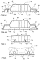
- FIG. 3 there is illustrated a panel 30 for acoustic treatment disposed at the rear of a front frame 32 of an air inlet including a portion of the lip 34 and the front of the inner duct 36 are shown.
- the inner duct 36 is delimited by a panel for the acoustic treatment 38 without frost treatment generally made of composite material.
- a longitudinal plane is a plane containing the longitudinal axis corresponding approximately to the axis of rotation of the engine.
- a transverse plane is a plane perpendicular to the longitudinal axis.
- the front of the panel 30 corresponds to the portion of the panel facing the lip while the rear panel 30 corresponds to the portion facing the outlet of the nacelle.
- hot air is injected into an annular duct 40 delimited by the lip 34 and the front frame 32.
- the hot air flows into the annular duct, carrying out approximately one rotational movement about the longitudinal axis, in a sense materialized by the arrows 42 on the Figures 9, 10, 11 , 13 and 14 .
- the panel for the acoustic treatment 38, the front frame, the lip, the means for injecting the hot air into the annular duct are not more detailed because they are known to those skilled in the art.
- the acoustic treatment panel 30 comprises, from the outside towards the inside, an acoustically resistive layer 44, at least one cellular structure 46 and a reflective layer 48 and channels 50 which extend from the front of the panel up to the back of the panel.
- the channels 50 are delimited by at least one wall interposed between the acoustically resistive layer 44 and the cellular structure 46.
- the channels 50 are made as described in the document FR-2917067 . Nevertheless, the invention is not limited to the embodiment illustrated in this document.
- a wall 52 can be shaped with grooves 54 so as to delimit once plated against the The wall 52 may comprise recesses 56 between the channels 50 to reduce the thickness of material passing through the acoustic waves, as shown in FIG. figure 5 .
- the channels 50 extend approximately in the longitudinal direction.
- the channels 50 could have a helix shape.
- Each channel 50 comprises an inlet 58 connected to the annular duct 40 and an outlet 60 connected to the inner duct 36.
- the panel comprises upstream of the channels 50 an annular channel 62 which extends over at least a portion of the circumference of the nacelle, at least one conduit providing communication between said annular channel 62 and the annular duct 40 upstream and several channels 50 opening into said annular channel 62 downstream.
- the inlets 58 and / or the outlets 60 of the channels 50 open into the annular channel (s) 62, 62 'with a flared shape.
- the annular channel 62 extends over the entire periphery of the nacelle.
- said annular channel 62 has a section greater than that of the channels 50 so as to homogenize the treatment of the frost on the circumference of the inner duct 36.
- the annular duct 62 also called stabilization chamber, has a section greater than or equal to 1.5 times the section of a channel 50.
- the annular channel 62 has a height greater than or equal to twice the height of a channel 50.
- the annular channel has a trapezoidal section in a longitudinal plane, the large base being oriented towards the acoustically resistive layer 44.
- the annular channel 62 comprises several inputs connected to the annular duct 40 and several outputs connected to the channels 50 and the inputs and outputs are not aligned in the longitudinal direction but offset along the circumference. This arrangement helps to obtain a better mixing of the hot air and to homogenize its temperature or its pressure before it crosses the channels 50.
- annular channel 62 can be provided upstream of the channels 50 and / or an annular channel 62 'downstream of the channels 50.
- each annular channel 62, 62 ' is delimited by a wall and the acoustically resistive layer 44.
- the annular channels 62, 62 'and the channels 50 are delimited by the same wall 52.
- This wall is shaped by any appropriate means, especially by forming.
- the wall 52 is in contact with the acoustically resistive layer 44 upstream of the annular channel 62 disposed upstream of the channels 50 and downstream of the annular channel 62 'disposed downstream of the channels 50.
- the layer Reflector 48 is pressed against the wall 52 at the level of the annular channels 62, 62 '.
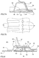
- the acoustically resistive layer 44 comprises orifices 64. As illustrated in FIG. Figure 7B , to ensure a better homogenization of the temperature, the outlet orifices 64 are not aligned with the channels 50 but staggered. Of Preferably, an outlet port 64 is disposed between two areas located in the extension of adjacent channels.
- the annular channel 62 ' comprises means for allowing the flow of air exiting the outlet orifices 64 to be tilted and thus limiting the disturbances of the flow of air flowing in the inner duct 36.
- the panel comprises a shim 66 pressed against the inner surface of the acoustically resistive layer 44 and whose upper surface 68 delimits with the wall 52 the annular channel 62 '.
- This shim 66 comprises for each outlet port 64 a conduit 70 for communicating the annular channel 62 'with the corresponding outlet 64.
- each duct 70 forms an angle ⁇ less than 50 ° with the outer surface of the acoustically resistive layer located after the corresponding outlet orifice.
- the upper surface 68 of the shim 66 comprises upstream a beveled shape at which the ducts 70 open out.
- the acoustic panel according to the invention is connected to the front frame at the level of the annular channel 62.
- the front frame 32 comprises an edge 72 curved rearwardly veneered the inner surface of the reflective layer 48, itself pressed against the wall 52 to the right of the annular channel 62 disposed upstream of the channels 50.
- at least one shim 74 is disposed in the annular channel 62 to the right of each means 76 providing the connection between the front frame 32 and the panel for the acoustic treatment 30 according to the invention.
- the shims 74 are spaced along the circumference so as to allow the passage of hot air between the annular duct 40 and the channels 50.
- each shim 74 is in the form of a tube whose axis is aligned with that of the connecting means 76, its height being equal to the height of the annular channel 62.
- the panel may comprise at the level of the annular channel 62 disposed upstream of the channels 50 a strip of material 78 which extends over at least a portion of the circumference, pressed against the acoustically resistive layer 44 and having for each connecting means 76 a boss 80 in the form of a hollow cylinder providing the wedge function 74.
- a strip of material 78 which extends over at least a portion of the circumference, pressed against the acoustically resistive layer 44 and having for each connecting means 76 a boss 80 in the form of a hollow cylinder providing the wedge function 74.
- several spacers 74 are connected by the material strip 78.
- the acoustic treatment panel 30 is connected to the wall delimiting the lip 34.
- annular piece 82 provides the connection between the wall delimiting the lip 34 and the acoustic panel 30 and advantageously the front frame 32.
- the annular piece 82 may be integral and extend over the entire periphery of the nacelle or be obtained from an assembly of several angular sectors.
- the annular piece 82 comprises at a first end a first portion 84 in the form of an annular band pressed and fixed against the inner surface of the wall forming the lip 34, and at the other end, a second portion 86 in the form of a strip interposed between the curved edge 72 of the front frame 32 and the wall delimiting the annular channel 62 of the acoustic panel 30, the second portion 86 being offset radially outwardly relative to the first portion 84 so that the outer surface of the acoustic panel 30 is in the extension of the outer surface of the wall defining the lip 34.
- This annular piece 82 comprises several ducts 88 making it possible to communicate the annular duct 40 with the inlets 90 of the annular channel 62 situated upstream of the acoustic panel 30.
- the air inlet comprises at least one duct for channeling the hot air from the annular duct 40 to the panel for the acoustic treatment 30.
- the annular piece 82 previously described comprises ducts 88.
- an intermediate piece 92 can ensure the junction between the front frame 32, the wall delimiting the lip 34 and the acoustic panel 30.
- This insert 92 comprises an annular body 94 with a bent plate 96 at the front that can be clad and fixed against the rear face of the front frame 32.
- the wall delimiting the lip 34 and the front end of the acoustic panel are plated and fixed to the inner face (that oriented towards the longitudinal axis of the nacelle) by all appropriate means.
- the annular body 94 comprises at its inner face recessed shapes which delimit conduits 98.
- the invention is not limited to these two variants for ducts capable of conveying hot air from the annular duct to the panel for acoustic treatment.
- ducts capable of conveying hot air from the annular duct to the panel for acoustic treatment.
- other forms of conduits or other solutions for delimiting a conduit could be envisaged.
- Each supply duct 88 and 98 comprises a said mouth portion 100 which opens into the annular duct 40.
- the mouthpiece 100 is used to channel the hot air in a direction referenced 102 which forms an angle ⁇ less than 60 ° with the direction 42 of flow of hot air in the annular conduit. This arrangement ensures to capture a greater flow of hot air.
- the ducts 88 have a mouth 100 whose direction 102 is contained in a plane perpendicular to the longitudinal axis of the nacelle.
- the mouths 100 are arranged in the same transverse plane.
- the mouths 100 are arranged in at least two transverse planes P, P '.
- the mouths 100 are distributed in two planes P, P 'and arranged in staggered rows.
- the mouths 100 open at the level of secant surfaces 104 with the direction 42 of flow of hot air in the annular conduit.
- the surfaces 104 are perpendicular to the direction 102 of the ducts.
- the ducts 98 have a mouth 100 whose direction 102 is secant with the plane perpendicular to the longitudinal axis of the nacelle and substantially tangent to the circumference of the inner duct of the nacelle.
- the mouths 100 are disposed at the inner surface of the wall delimiting the lip 34.
- a piece is pressed against the inner face of the wall delimiting the lip 34, said piece having grooves which each delimit a duct.
- the wall delimiting the lip 34 being curved, a component of the direction 102 of the mouth 100 of the ducts is oriented towards the longitudinal axis of the nacelle.
- the mouths 100 are disposed in a plane parallel to the direction 42 of flow of hot air in the annular conduit.
- the mouths 100 open at the level of intersecting surfaces 106 with the direction 42 flow of hot air into the annular duct.
- the surfaces 106 are perpendicular to the direction 102 of the ducts.
Description
La présente invention se rapporte à un panneau pour le traitement acoustique intégrant des canaux d'air chaud et au moins un canal annulaire.The present invention relates to a panel for acoustic treatment incorporating hot air channels and at least one annular channel.
Un ensemble propulsif d'aéronef comprend une nacelle dans laquelle est disposée de manière sensiblement concentrique une motorisation.An aircraft propulsion unit comprises a nacelle in which is arranged in a substantially concentric engine.
Le document
Comme illustré sur la
La nacelle comprend également un cadre avant 22 qui délimite avec la lèvre 14 un conduit annulaire 24 qui peut être utilisé pour canaliser de l'air chaud pour le traitement du givre.The nacelle also comprises a
Pour limiter l'impact des nuisances sonores, des techniques ont été développées pour réduire le bruit interne, notamment en disposant, au niveau des parois du conduit intérieur 20, des panneaux ou revêtements visant à absorber une partie de l'énergie sonore, notamment en utilisant le principe des résonateurs d'Helmholtz.To limit the impact of noise nuisance, techniques have been developed to reduce internal noise, in particular by arranging, at the walls of the
Pour optimiser le traitement acoustique, ces panneaux doivent recouvrir la plus grande surface. Certains panneaux 26 pour le traitement acoustique peuvent recouvrir le conduit intérieur 20, ces derniers distants du cadre avant ne comportant pas la fonction du traitement du givre. D'autres peuvent être disposés dans le conduit annulaire 24 à l'avant du cadre 22 et combiner les fonctions du traitement acoustique et du traitement du givre. Enfin, un panneau 28 pour le traitement acoustique avec des matériaux résistants à la chaleur peut être intercalé entre le cadre avant 22 et les panneaux 26. Ce panneau 28 intègre également la fonction du traitement du givre et comprend des moyens pour capter l'air chaud dans le conduit annulaire 24 et le rejeter à l'arrière dans le conduit intérieur 20.To optimize acoustic processing, these panels must cover the largest area. Some
Un tel panneau combinant les fonctions du traitement acoustique et du traitement du givre est notamment décrit dans le brevet
Cette solution permet de limiter les risques de communication entre l'intérieur des canaux et les cellules de la structure alvéolaire, et donc les risques de perturbation du traitement acoustique.This solution makes it possible to limit the risks of communication between the inside of the channels and the cells of the honeycomb structure, and therefore the risks of disturbance of the acoustic treatment.
Selon un autre avantage, l'air chaud occupe un volume nettement inférieur par rapport aux solutions antérieures selon lesquelles il occupe le volume de certaines cellules de la structure alvéolaire, ce qui permet d'obtenir d'une part une meilleure concentration de l'air chaud contre la paroi à dégivrer renforçant l'efficacité du dégivrage, et d'autre part, une pression pneumatique plus élevée limitant le risque d'une pression à l'intérieur de la structure inférieure à celle de l'extérieur et donc la pénétration de l'air extérieur à l'intérieur du système de dégivrage.According to another advantage, the hot air occupies a much smaller volume compared to previous solutions according to which it occupies the volume of certain cells of the honeycomb structure, which makes it possible on the one hand to obtain a better concentration of air hot against the wall to be defrosted enhancing the efficiency of the defrosting, and secondly, a higher pneumatic pressure limiting the risk of pressure inside the structure less than that of the outside and therefore the penetration of outside air inside the defrost system.
Selon un autre avantage, l'air chaud est en contact permanent avec la peau à dégivrer, ce qui permet d'améliorer les échanges et de réduire la température de l'air chaud refoulé en sortie du système de dégivrage, ce qui permet de le rejeter sans risque de brûlures de la paroi traversée, notamment lorsque cette dernière est réalisée en un matériau sensible à la chaleur tel que le composite. En général chaque canal prévu pour canaliser l'air chaud communique à une première extrémité avec le conduit annulaire et débouche via un orifice de sortie dans le conduit intérieur 20. Ces canaux s'étendent selon la direction longitudinale et sont répartis sur toute la circonférence du conduit intérieur 20. Au niveau du conduit annulaire 24, l'air chaud est injecté généralement en un point de la circonférence et circule dans le conduit annulaire, en y faisant plusieurs tours. Des moyens sont prévus pour homogénéiser la température de l'air à l'intérieur du conduit annulaire. Pour assurer le transfert de l'air chaud depuis le conduit annulaire vers les canaux, il est nécessaire de prévoir une pièce intercalaire qui assure la fonction de jonction entre la paroi délimitant la lèvre, le cadre avant et le panneau pour le traitement acoustique 28. Cette pièce comprend des canaux pour permettre de canaliser l'air chaud depuis le conduit annulaire vers les canaux du panneau acoustique. Cette pièce intercalaire et son montage sont relativement complexes car il est nécessaire que les conduits présents au niveau de cette pièce soient alignés avec les conduits du panneau pour le traitement acoustique. Selon un mode de réalisation, cette pièce se présente sous la forme d'une plaque avec des sillons au niveau de sa face en regard de la couche acoustiquement résistive qui délimitent chacun un conduit. Selon une autre contrainte, il est nécessaire de réduire la superficie des surfaces non traitées sur le plan acoustique pour optimiser le traitement acoustique.According to another advantage, the hot air is in permanent contact with the skin to be defrosted, which makes it possible to improve exchanges and to reduce the temperature of the hot air discharged at the outlet of the de-icing system, which makes it possible to reject without risk of burns of the wall through, especially when the latter is made of a heat-sensitive material such as the composite. In general, each channel intended to channel the hot air communicates at a first end with the annular duct and opens via an outlet orifice into the
Aussi, la présente invention vise à pallier les inconvénients de l'art antérieur en proposant un panneau pour le traitement acoustique intégrant des canaux pour la fonction du traitement du givre, avec un canal annulaire pour canaliser l'air chaud en direction des canaux permettant d'en simplifier la conception.Also, the present invention aims at overcoming the drawbacks of the prior art by proposing a panel for acoustic treatment integrating channels for the function of the frost treatment, with an annular channel for channeling the hot air towards the channels enabling simplify the design.
A cet effet, l'invention a pour objet une nacelle d'aéronef comprenant une lèvre prolongée par un conduit intérieur formant une entrée d'air, un cadre avant délimitant avec ladite lèvre un conduit annulaire dans lequel circule de l'air chaud ainsi qu'un panneau pour le traitement acoustique comportant de l'extérieur vers l'intérieur une couche acoustiquement résistive, au moins une structure alvéolaire et une couche réflectrice ainsi que des canaux permettant de canaliser de l'air chaud avec chacun une entrée communiquant avec le conduit annulaire et une sortie communiquant avec le conduit intérieur, caractérisée en ce que le panneau pour le traitement acoustique comprend, en amont des canaux, un canal annulaire qui s'étend sur au moins une partie de la circonférence de la nacelle, au moins un conduit assurant la communication entre ledit canal annulaire et le conduit annulaire en amont et plusieurs canaux débouchant dans ledit canal annulaire en aval, le panneau pour le traitement acoustique étant relié au cadre avant au droit du canal annulaire.For this purpose, the invention relates to an aircraft nacelle comprising a lip extended by an inner duct forming an air inlet, a front frame delimiting with said lip an annular duct in which circulates hot air as well as an acoustic treatment panel comprising, from the outside towards the inside, an acoustically resistive layer, at least one cellular structure and a reflective layer, and channels for channeling hot air with each an inlet communicating with the duct; annular and an outlet communicating with the inner duct, characterized in that the panel for acoustic treatment comprises, upstream of the channels, an annular channel which extends over at least a portion of the circumference of the nacelle, at least one duct providing communication between said annular channel and the annular duct upstream and several channels opening into said annular channel downstream, the panel for r acoustic treatment being connected to the front frame to the right of the annular channel.
D'autres caractéristiques et avantages ressortiront de la description qui va suivre de l'invention, description donnée à titre d'exemple uniquement, en regard des dessins annexés sur lesquels :
- la
figure 1 est une coupe longitudinale d'une partie d'une entrée d'air selon l'art antérieur, - la
figure 2 est une coupe illustrant en détails un panneau pour le traitement acoustique selon l'art antérieur, - la
figure 3 est une coupe d'une partie d'une entrée d'air selon l'invention, - la
figure 4A est une coupe longitudinale selon un premier plan de coupe d'un panneau pour le traitement acoustique selon l'invention, - la
figure 4B est une coupe longitudinale selon un deuxième plan de coupe d'un panneau pour le traitement acoustique selon l'invention, - la
figure 5 est une coupe transversale selon un premier plan de coupe d'un panneau pour le traitement acoustique selon l'invention, - la
figure 6 est une coupe transversale selon un deuxième plan de coupe d'un panneau pour le traitement acoustique selon l'invention, - la
figure 7A est une coupe longitudinale illustrant en détails une chambre de stabilisation disposée à l'arrière du panneau pour le traitement acoustique selon l'invention, - la
figure 7B est un schéma illustrant la répartition selon la circonférence des canaux d'air chaud et des sorties du panneau pour le traitement acoustique selon l'invention, - la
figure 8 est une coupe longitudinale illustrant en détails un mode de réalisation d'une chambre de stabilisation prévue à l'avant d'un panneau pour le traitement acoustique, - la
figure 9 est une coupe transversale d'un mode de réalisation des entrées des canaux d'un panneau pour le traitement acoustique de l'invention, - la
figure 10 est une vue depuis l'intérieur du conduit annulaire d'un autre mode de réalisation des entrées des canaux d'un panneau pour le traitement acoustique de l'invention, - la
figure 11 est une coupe transversale du mode de réalisation illustré sur lafigure 10 , - la
figure 12 est une coupe longitudinale d'un autre mode de réalisation des entrées des canaux d'un panneau pour le traitement acoustique de l'invention, - la
figure 13 est une coupe selon la circonférence des entrées des canaux illustrées sur lafigure 12 , et - la
figure 14 est une coupe selon la circonférence d'une variante du mode de réalisation illustré sur lafigure 13 .
- the
figure 1 is a longitudinal section of a portion of an air inlet according to the prior art, - the
figure 2 is a section illustrating in detail a panel for acoustic treatment according to the prior art, - the
figure 3 is a section of a part of an air inlet according to the invention, - the
Figure 4A is a longitudinal section along a first sectional plane of a panel for acoustic treatment according to the invention, - the
Figure 4B is a longitudinal section along a second section plane of a panel for the acoustic treatment according to the invention, - the
figure 5 is a cross-section along a first sectional plane of a panel for acoustic treatment according to the invention, - the
figure 6 is a cross section along a second sectional plane of a panel for acoustic treatment according to the invention, - the
Figure 7A is a longitudinal section illustrating in detail a stabilization chamber disposed at the rear of the panel for the acoustic treatment according to the invention, - the
Figure 7B is a diagram illustrating the circumferential distribution of the hot air ducts and panel outputs for acoustic treatment according to the invention, - the
figure 8 is a longitudinal section illustrating in detail one embodiment of a stabilization chamber provided at the front of a panel for acoustic treatment, - the
figure 9 is a cross section of an embodiment of the channel inputs of a panel for the acoustic treatment of the invention, - the
figure 10 is a view from inside the annular duct of another embodiment of the channel inputs of a panel for the acoustic treatment of the invention, - the
figure 11 is a cross-section of the embodiment illustrated on thefigure 10 , - the
figure 12 is a longitudinal section of another embodiment of the channel inputs of a panel for the acoustic treatment of the invention, - the
figure 13 is a section along the circumference of the channel inputs shown on thefigure 12 , and - the
figure 14 is a circumferential section of a variant of the embodiment illustrated in FIG.figure 13 .
Sur la
Pour la suite de la description, un plan longitudinal est un plan contenant l'axe longitudinal correspondant approximativement à l'axe de rotation de la motorisation. Un plan transversal est un plan perpendiculaire à l'axe longitudinal. De plus, l'avant du panneau 30 correspond à la partie du panneau orientée vers la lèvre alors que l'arrière du panneau 30 correspond à la partie orientée vers la sortie de la nacelle.For the rest of the description, a longitudinal plane is a plane containing the longitudinal axis corresponding approximately to the axis of rotation of the engine. A transverse plane is a plane perpendicular to the longitudinal axis. In addition, the front of the
Selon l'invention, pour assurer le traitement du givre, de l'air chaud est injecté dans un conduit annulaire 40 délimité par la lèvre 34 et le cadre avant 32. L'air chaud s'écoule dans le conduit annulaire en effectuant approximativement un mouvement de rotation autour de l'axe longitudinal, selon un sens matérialisé par les flèches 42 sur les
Pour la suite de la description, le panneau pour le traitement acoustique 38, le cadre avant, la lèvre, les moyens pour injecter l'air chaud dans le conduit annulaire ne sont pas plus détaillés car ils sont connus de l'homme du métier.For the rest of the description, the panel for the
De manière connue, le panneau pour le traitement acoustique 30 comprend de l'extérieur vers l'intérieur une couche acoustiquement résistive 44, au moins une structure alvéolaire 46 et une couche réflectrice 48 et des canaux 50 qui s'étendent depuis l'avant du panneau jusqu'à l'arrière du panneau. Avantageusement, les canaux 50 sont délimités par au moins une paroi intercalée entre la couche acoustiquement résistive 44 et la structure alvéolaire 46.In known manner, the
Selon un mode de réalisation, les canaux 50 sont réalisés comme décrits dans le document
La mise en forme de la paroi 52, l'assemblage de la couche acoustiquement résistive 44 et de la paroi 52, le mode de réalisation des évidements 56 et l'assemblage de la structure alvéolaire et de la couche réflectrice ne sont pas plus détaillés car différentes solutions techniques peuvent être envisagées. Selon un mode de réalisation, les canaux 50 s'étendent approximativement selon la direction longitudinale. En variante, les canaux 50 pourraient avoir une forme d'hélice.The shaping of the
Chaque canal 50 comprend une entrée 58 reliée au conduit annulaire 40 et une sortie 60 reliée au conduit intérieur 36. Selon l'invention, le panneau comprend en amont des canaux 50 un canal annulaire 62 qui s'étend sur au moins une partie de la circonférence de la nacelle, au moins un conduit assurant la communication entre ledit canal annulaire 62 et le conduit annulaire 40 en amont et plusieurs canaux 50 débouchant dans ledit canal annulaire 62 en aval. Le fait de prévoir un canal annulaire permet de simplifier la conception dans la mesure où le ou les conduits qui communiquent avec le conduit annulaire 40 ne sont pas nécessairement alignés avec les canaux 50.Each
De préférence, les entrées 58 et/ou les sorties 60 des canaux 50 débouchent dans la ou les canaux annulaires 62, 62' avec une forme évasée. Avantageusement, le canal annulaire 62 s'étend sur toute la périphérie de la nacelle.Preferably, the
De préférence, ledit canal annulaire 62 a une section supérieure à celle des canaux 50 de manière à homogénéiser le traitement du givre sur la circonférence du conduit intérieur 36.Preferably, said
Pour assurer un brassage satisfaisant et réduire les disparités de température et/ou de pression le long de la circonférence, le conduit annulaire 62, également appelé chambre de stabilisation, a une section supérieure ou égale à 1,5 fois la section d'un canal 50. De préférence, le canal annulaire 62 a une hauteur supérieure ou égale au double de la hauteur d'un canal 50. De préférence, le canal annulaire a une section trapézoïdale dans un plan longitudinal, la grande base étant orientée vers la couche acoustiquement résistive 44.To ensure satisfactory mixing and to reduce temperature and / or pressure disparities along the circumference, the
Avantageusement, le canal annulaire 62 comprend plusieurs entrées reliées au conduit annulaire 40 et plusieurs sorties reliées aux canaux 50 et les entrées et les sorties ne sont pas alignées selon la direction longitudinale mais décalées selon la circonférence. Cet agencement contribue à obtenir un meilleur brassage de l'air chaud et à homogénéiser sa température ou sa pression avant qu'il ne traverse les canaux 50.Advantageously, the
De préférence, on peut prévoir un canal annulaire 62 en amont des canaux 50 et/ou un canal annulaire 62' en aval des canaux 50.Preferably, an
Selon un mode de réalisation, chaque canal annulaire 62, 62' est délimité par une paroi et la couche acoustiquement résistive 44.According to one embodiment, each
Avantageusement, les canaux annulaires 62, 62' et les canaux 50 sont délimités par la même paroi 52. Cette paroi est mise en forme par tous moyens appropriés, notamment par formage.Advantageously, the
Selon un mode de réalisation, la paroi 52 est en contact avec la couche acoustiquement résistive 44 en amont du canal annulaire 62 disposé en amont des canaux 50 et en aval du canal annulaire 62' disposé en aval des canaux 50. En complément, la couche réflectrice 48 est plaquée contre la paroi 52 au niveau des canaux annulaires 62, 62'.According to one embodiment, the
Au niveau du canal annulaire 62' prévu en aval des canaux 50, la couche acoustiquement résistive 44 comprend des orifices 64. Comme illustré sur la
Avantageusement, le canal annulaire 62' comprend des moyens pour permettre d'incliner le flux d'air sortant des orifices de sortie 64 et limiter ainsi les perturbations du flux d'air circulant dans le conduit intérieur 36. A cet effet, le panneau comprend une cale 66 plaquée contre la surface intérieure de la couche acoustiquement résistive 44 et dont la surface supérieure 68 délimite avec la paroi 52 le canal annulaire 62'. Cette cale 66 comprend pour chaque orifice de sortie 64 un conduit 70 permettant de faire communiquer le canal annulaire 62' avec l'orifice de sortie 64 correspondant. Avantageusement, chaque conduit 70 forme un angle a inférieur à 50° avec la surface extérieure de la couche acoustiquement résistive située après l'orifice de sortie correspondant.Advantageously, the annular channel 62 'comprises means for allowing the flow of air exiting the outlet orifices 64 to be tilted and thus limiting the disturbances of the flow of air flowing in the
Pour faciliter l'écoulement de l'air, la surface supérieur 68 de la cale 66 comprend en amont une forme en biseau au niveau de laquelle débouchent les conduits 70.To facilitate the flow of air, the
Pour simplifier le circuit d'air et réduire au maximum les surfaces non traitées sur le plan acoustique, le panneau acoustique selon l'invention est relié au cadre avant au niveau du canal annulaire 62.To simplify the air circuit and to minimize acoustically untreated surfaces, the acoustic panel according to the invention is connected to the front frame at the level of the
A cet effet, le cadre avant 32 comprend un bord 72 recourbé vers l'arrière plaqué conte la surface intérieure de la couche réflectrice 48, elle-même plaquée contre la paroi 52 au droit du canal annulaire 62 disposé en amont des canaux 50. Pour limiter les risques d'écrasement du canal annulaire 62, au moins une cale 74 est disposée dans le canal annulaire 62 au droit de chaque moyen 76 assurant la liaison entre le cadre avant 32 et le panneau pour le traitement acoustique 30 selon l'invention. Dans un plan transversal, les cales 74 sont espacées le long de la circonférence de manière à permettre le passage de l'air chaud entre le conduit annulaire 40 et les canaux 50.For this purpose, the
Selon un mode de réalisation simplifié, chaque cale 74 se présente sous la forme d'un tube dont l'axe est aligné avec celui du moyen de liaison 76, sa hauteur étant égale à la hauteur du canal annulaire 62.According to a simplified embodiment, each
En variante, pour simplifier l'assemblage, le panneau peut comprendre au niveau du canal annulaire 62 disposé en amont des canaux 50 une bande de matière 78 qui s'étend sur au moins une partie de la circonférence, plaquée contre la couche acoustiquement résistive 44 et comportant pour chaque moyen de liaison 76 un bossage 80 sous forme d'un cylindre creux assurant la fonction de cale 74. Ainsi, selon ce mode de réalisation, plusieurs cales 74 sont reliées par la bande de matière 78.Alternatively, to simplify the assembly, the panel may comprise at the level of the
De préférence, le panneau pour le traitement acoustique 30 est relié à la paroi délimitant la lèvre 34.Preferably, the
A cet effet, une pièce annulaire 82 assure la liaison entre d'une part la paroi délimitant la lèvre 34, et d'autre part, le panneau acoustique 30 et avantageusement le cadre avant 32.For this purpose, an
Selon les cas, la pièce annulaire 82 peut être d'un seul tenant et s'étendre sur toute la périphérie de la nacelle ou être obtenue à partir d'un assemblage de plusieurs secteurs angulaires.Depending on the case, the
Selon un mode de réalisation illustré notamment sur la
Cette pièce annulaire 82 comprend plusieurs conduits 88 permettant de faire communiquer le conduit annulaire 40 avec les entrées 90 du canal annulaire 62 situé en amont du panneau acoustique 30.This
Quel que soit le panneau pour le traitement acoustique 30, l'entrée d'air comprend au moins un conduit permettant de canaliser l'air chaud depuis le conduit annulaire 40 jusqu'au panneau pour le traitement acoustique 30.Whatever the
Selon une première variante, illustré sur les
Selon une autre variante, illustrée sur les
Cependant, l'invention n'est pas limitée à ces deux variantes pour les conduits susceptibles d'acheminer l'air chaud depuis le conduit annulaire vers le panneau pour le traitement acoustique. Ainsi, d'autres formes de conduits ou d'autres solutions pour délimiter un conduit pourraient être envisagées.However, the invention is not limited to these two variants for ducts capable of conveying hot air from the annular duct to the panel for acoustic treatment. Thus, other forms of conduits or other solutions for delimiting a conduit could be envisaged.
Chaque conduit d'alimentation 88 et 98 comprend une portion dite embouchure 100 qui débouche dans le conduit annulaire 40.Each
Selon l'invention, l'embouchure 100 permet de canaliser l'air chaud selon une direction référencée 102 qui forme un angle β inférieur à 60° avec la direction 42 d'écoulement de l'air chaud dans le conduit annulaire. Cet agencement assure de capter un plus grand débit d'air chaud.According to the invention, the
Selon des variantes illustrées notamment sur les
Selon une première variante illustrée sur la
Selon une autre variante illustrée sur les
Selon d'autres variantes illustrées notamment sur les
Selon un autre mode de réalisation illustré sur la
Claims (8)
- Aircraft nacelle comprising a lip (34) extended by an internal conduit (36) forming an air intake, a front frame (32) defining with said lip (34) an annular channel (40) through which hot air circulates, as well as a panel for acoustic treatment comprising from outside inwardly an acoustic resistive layer (44), at least one honeycomb structure (46) and a reflective layer (48) as well ducts (50) for channeling hot air with each duct having an inlet communicating with annular channel (40) and an outlet communicating with inner conduit (36), characterized in that the panel for acoustic treatment (30) is arranged a rearwardly front frame (32) and connected to said front frame (32) by connecting means (76), in that said panel for acoustic treatment (30) comprises, upstream from ducts (50), an annular channel (62) which extends over at least a portion of the nacelle circumference, at least one conduit providing communication between said annular channel (62) and upstream annular channel (40) and a plurality of ducts (50) opening into said downstream annular channel (62) and in that at least one wedge (74) is positioned in annular channel (62), with each connecting means (76) providing the connection between front frame (32) and the panel for acoustic treatment (30), for limiting the crushing risk.
- Aircraft nacelle according to Claim 1, wherein the front frame (32) comprises a rearwardly bent edge (72) pressed onto the wall delimiting annular channel (62), and wherein at least one wedge (74) is arranged inside annular channel (62) in regard with each connecting means (76) providing the connection between front frame (32) and the panel for acoustic treatment (30).
- Aircraft nacelle according to any of the Claims 1 or 2, wherein said panel comprises in the annular channel (62) a material web (78) which extends over at least a portion of the circumference having for each connecting means (76) embossment (80) which function as a wedge (74).
- Aircraft nacelle according to any Claims 1 to 3, wherein the annular channel (62) extends over the entire nacelle circumference.
- Aircraft nacelle according to any of the Claims 1 or 4, wherein the annular channel (62) has a cross-section greater than or equal to the section of one duct (50).
- Aircraft nacelle according to Claim 5, wherein the annular channel (62) has a trapezoidal cross-section in a longitudinal plane, the large base being oriented toward acoustic resistive layer (44).
- Aircraft nacelle according to any of the Claims 1 to 6, wherein the annular channel (62) comprises several inlets and several outlets, inlets and outlets being not aligned in the longitudinal direction but offset along the circumference.
- Aircraft nacelle according to one of the preceding claims, wherein the annular channel (62) and ducts (50) are delimited by a common wall (52) shaped and pressed against the acoustic resistive layer.
Applications Claiming Priority (1)
| Application Number | Priority Date | Filing Date | Title |
|---|---|---|---|
| FR1158896A FR2980776B1 (en) | 2011-10-03 | 2011-10-03 | AIRCRAFT NACELLE COMPRISING A PANEL FOR ACOUSTIC TREATMENT INTEGRATING HOT AIR CHANNELS AND AT LEAST ONE ANNULAR CHANNEL |
Publications (3)
| Publication Number | Publication Date |
|---|---|
| EP2578496A2 EP2578496A2 (en) | 2013-04-10 |
| EP2578496A3 EP2578496A3 (en) | 2014-07-30 |
| EP2578496B1 true EP2578496B1 (en) | 2016-07-06 |
Family
ID=46968108
Family Applications (1)
| Application Number | Title | Priority Date | Filing Date |
|---|---|---|---|
| EP12306186.3A Active EP2578496B1 (en) | 2011-10-03 | 2012-09-28 | Acoustic treatment panel including hot-air channels and at least one annular channel |
Country Status (4)
| Country | Link |
|---|---|
| US (1) | US9353648B2 (en) |
| EP (1) | EP2578496B1 (en) |
| CN (1) | CN103029842B (en) |
| FR (1) | FR2980776B1 (en) |
Cited By (1)
| Publication number | Priority date | Publication date | Assignee | Title |
|---|---|---|---|---|
| EP3792469B1 (en) * | 2019-09-12 | 2022-04-20 | Airbus Operations (S.A.S.) | Air intake, nacelle, propulsion assembly and aircraft with grooved lip |
Families Citing this family (15)
| Publication number | Priority date | Publication date | Assignee | Title |
|---|---|---|---|---|
| WO2010086560A2 (en) * | 2009-02-02 | 2010-08-05 | Airbus Operations Sas | Aircraft nacelle including an optimised acoustic processing system |
| FR2943624B1 (en) * | 2009-03-27 | 2011-04-15 | Airbus France | AIRCRAFT NACELLE COMPRISING AN ENHANCED EXTERIOR WALL |
| FR2980775B1 (en) | 2011-10-03 | 2014-07-11 | Airbus Operations Sas | AIRCRAFT NACELLE COMPRISING A PANEL FOR ACOUSTIC TREATMENT INTEGRATING HOT AIR CHANNELS AND AT LEAST ONE STABILIZING CHAMBER |
| DE102012003680A1 (en) | 2012-02-23 | 2013-08-29 | Pfeiffer Vacuum Gmbh | vacuum pump |
| GB201322832D0 (en) * | 2013-12-23 | 2014-02-12 | Rolls Royce Plc | A flow outlet |
| FR3023538B1 (en) * | 2014-07-11 | 2016-07-15 | Aircelle Sa | TURBOJET NACELLE FRONT LEVER HAVING HOT AIR DRILLING UPSTREAM ACOUSTIC PANELS |
| US10533497B2 (en) * | 2016-04-18 | 2020-01-14 | United Technologies Corporation | Short inlet with integrated liner anti-icing |
| US10221765B2 (en) | 2016-08-26 | 2019-03-05 | Honeywell International Inc. | Anti-icing exhaust system |
| FR3055612B1 (en) * | 2016-09-06 | 2022-03-04 | Airbus Operations Sas | COMPARTMENTED STRUCTURE FOR ACOUSTIC TREATMENT AND DE-ICING OF AN AIRCRAFT NACELLE AND AIRCRAFT NACELLE INCORPORATING SAID STRUCTURE |
| FR3087489B1 (en) * | 2018-10-18 | 2022-12-09 | Airbus Operations Sas | FRONT PART OF AN AIRCRAFT PROPULSION GROUP NACELLE COMPRISING A MAIN STRUCTURE PROPAGATION PATH BETWEEN AN AIR INTAKE LIP AND A BACK SKIN OF AN ACOUSTIC PANEL |
| FR3087420B1 (en) * | 2018-10-19 | 2021-03-12 | Airbus Operations Sas | AIRCRAFT ENGINE NACELLE INCLUDING AN ICE PROTECTION SYSTEM. |
| FR3095420B1 (en) * | 2019-04-26 | 2023-04-21 | Safran Nacelles | Nacelle air inlet and nacelle comprising such an air inlet |
| FR3096662B1 (en) * | 2019-05-27 | 2022-08-12 | Safran Nacelles | Turbomachine nacelle air inlet lip comprising an acoustic device and method of manufacturing such a lip |
| FR3099913A1 (en) * | 2019-08-13 | 2021-02-19 | Airbus Operations | Front part of the nacelle of an aircraft propulsion unit, the front frame of which is linked to an outer wall without passing through it |
| DE102020200204A1 (en) * | 2020-01-09 | 2021-07-15 | Siemens Aktiengesellschaft | Ceramic resonator for combustion chamber systems and combustion chamber systems |
Family Cites Families (18)
| Publication number | Priority date | Publication date | Assignee | Title |
|---|---|---|---|---|
| US3933327A (en) | 1974-08-30 | 1976-01-20 | Rohr Industries, Inc. | Aircraft anti-icing plenum |
| DE4302607C2 (en) | 1993-01-30 | 2002-12-05 | Johnson Contr Interiors Gmbh | Sun visors for vehicles |
| US5841079A (en) | 1997-11-03 | 1998-11-24 | Northrop Grumman Corporation | Combined acoustic and anti-ice engine inlet liner |
| FR2820716B1 (en) * | 2001-02-15 | 2003-05-30 | Eads Airbus Sa | PROCESS FOR DEFROSTING BY FORCED CIRCULATION OF A FLUID, OF A REACTION ENGINE AIR INLET COVER AND DEVICE FOR ITS IMPLEMENTATION |
| US7588212B2 (en) | 2003-07-08 | 2009-09-15 | Rohr Inc. | Method and apparatus for noise abatement and ice protection of an aircraft engine nacelle inlet lip |
| US7923668B2 (en) | 2006-02-24 | 2011-04-12 | Rohr, Inc. | Acoustic nacelle inlet lip having composite construction and an integral electric ice protection heater disposed therein |
| FR2917067B1 (en) * | 2007-06-08 | 2009-08-21 | Airbus France Sas | COATING FOR ACOUSTIC TREATMENT INCORPORATING THE FUNCTION OF TREATING FROST WITH HOT AIR |
| GB0713526D0 (en) | 2007-07-12 | 2007-08-22 | Rolls Royce Plc | An acoustic panel |
| FR2924409B1 (en) | 2007-12-03 | 2010-05-14 | Airbus France | AIRCRAFT NACELLE COMPRISING MEANS FOR HOT AIR EXHAUST |
| FR2925463B1 (en) * | 2007-12-21 | 2010-04-23 | Airbus France | STRUCTURE FOR ACOUSTIC TREATMENT MORE PARTICULARLY ADAPTED TO AIR INTAKE OF AN AIRCRAFT NACELLE |
| CN102099556B (en) | 2008-07-30 | 2014-03-12 | 埃尔塞乐公司 | Air intake structure for turbojet engine nacelle with pneumatic de-icing |
| EP2318683A2 (en) | 2008-07-30 | 2011-05-11 | Aircelle | Acoustic attenuation panel for aircraft engine nacelle |
| FR2941675B1 (en) * | 2009-02-02 | 2012-08-17 | Airbus France | AIRCRAFT NACELLE COMPRISING AN OPTIMIZED ACOUSTIC TREATMENT SYSTEM. |
| FR2952032B1 (en) | 2009-11-05 | 2012-04-06 | Airbus Operations Sas | AIRCRAFT NACELLE COMPRISING AN OPTIMIZED ACOUSTIC TREATMENT SYSTEM |
| FR2954282B1 (en) | 2009-12-22 | 2012-02-17 | Airbus Operations Sas | NACELLE INCORPORATING A JUNCTION ELEMENT BETWEEN A LIP AND AN ACOUSTICAL ATTENUATION PANEL |
| FR2976557B1 (en) | 2011-06-20 | 2013-07-12 | Airbus Operations Sas | METHOD FOR MAKING A PANEL FOR ACOUSTIC TREATMENT INCORPORATING THE FUNCTION OF TREATING FROZEN WITH HOT AIR |
| FR2980775B1 (en) | 2011-10-03 | 2014-07-11 | Airbus Operations Sas | AIRCRAFT NACELLE COMPRISING A PANEL FOR ACOUSTIC TREATMENT INTEGRATING HOT AIR CHANNELS AND AT LEAST ONE STABILIZING CHAMBER |
| FR2980774B1 (en) | 2011-10-03 | 2013-10-25 | Airbus Operations Sas | AIRCRAFT NACELLE COMPRISING A HOT AIR SUPPLY DEVICE OF A PANEL COMBINING ACOUSTIC AND FROZEN TREATMENTS |
-
2011
- 2011-10-03 FR FR1158896A patent/FR2980776B1/en not_active Expired - Fee Related
-
2012
- 2012-09-28 EP EP12306186.3A patent/EP2578496B1/en active Active
- 2012-10-03 US US13/573,802 patent/US9353648B2/en active Active
- 2012-10-08 CN CN201210415280.3A patent/CN103029842B/en active Active
Cited By (1)
| Publication number | Priority date | Publication date | Assignee | Title |
|---|---|---|---|---|
| EP3792469B1 (en) * | 2019-09-12 | 2022-04-20 | Airbus Operations (S.A.S.) | Air intake, nacelle, propulsion assembly and aircraft with grooved lip |
Also Published As
| Publication number | Publication date |
|---|---|
| US20130224000A1 (en) | 2013-08-29 |
| US9353648B2 (en) | 2016-05-31 |
| CN103029842B (en) | 2017-04-12 |
| FR2980776B1 (en) | 2014-08-22 |
| FR2980776A1 (en) | 2013-04-05 |
| EP2578496A3 (en) | 2014-07-30 |
| CN103029842A (en) | 2013-04-10 |
| EP2578496A2 (en) | 2013-04-10 |
Similar Documents
| Publication | Publication Date | Title |
|---|---|---|
| EP2578496B1 (en) | Acoustic treatment panel including hot-air channels and at least one annular channel | |
| EP2578842B1 (en) | Aircraft nacelle comprising a device for supplying hot air to a panel combining acoustic and ice treatments | |
| EP2578495B1 (en) | Acoustic treatment panel including hot-air channels and at least one stabilising chamber | |
| EP2152583B1 (en) | Coating for acoustic treatment including a hot-air de-icing function | |
| CA2707655C (en) | Aircraft nacelle including an optimised ice treatment system | |
| EP1999020B1 (en) | Structure for an air inlet lip for a nacelle with electric de-icing and comprising an acoustic attenuation zone | |
| EP2391542B1 (en) | Engine nacelle having a noise reducing structure | |
| EP1232944B1 (en) | Deicing method with forced circulaion for jet engine intake fairing and device for the implementation of said method | |
| EP2537753B1 (en) | Method for producing an acoustic treatment panel including the function of de-icing with hot air | |
| EP2537754B1 (en) | Method for producing an acoustic treatment panel including channels adjacent to a cellular structure | |
| FR3041937A1 (en) | COMPARTMENTED STRUCTURE FOR THE ACOUSTIC TREATMENT AND DEFROSTING OF AN AIRCRAFT NACELLE AND AN AIRCRAFT NACELLE INCORPORATING THE SAID STRUCTURE | |
| EP2487676A1 (en) | Acoustic panel treatment with a junction between two parties and repair method of an acoustic panel | |
| EP2791006B1 (en) | Air intake structure for turbojet engine nacelle | |
| CA2850455A1 (en) | Method of manufacturing a sound absorbing panel | |
| FR3055612A1 (en) | COMPARTMENTED STRUCTURE FOR THE ACOUSTIC TREATMENT AND DEFROSTING OF AN AIRCRAFT NACELLE AND AN AIRCRAFT NACELLE INCORPORATING THE SAID STRUCTURE | |
| FR2952032A1 (en) | Aircraft nacelle, has heat-conducting material element provided between lip and duct to ensure continuity of aerodynamic surfaces and heat propagation, and comprising heat resistant material coating for acoustic treatment | |
| FR2962586A1 (en) | Panel for performing acoustic treatment in nacelle of aircraft, has resistive layer whose face is in contact with air flow in honeycomb structure and reflecting layer, and openings form angle with layer lower than specific degree | |
| FR2941675A1 (en) | Nacelle for aircraft, has heat conducting element placed between lip and conduit to ensure continuity of aerodynamic surfaces of lip and propagation of heat from space towards back so that junction zone is treated on frost plane |
Legal Events
| Date | Code | Title | Description |
|---|---|---|---|
| PUAI | Public reference made under article 153(3) epc to a published international application that has entered the european phase |
Free format text: ORIGINAL CODE: 0009012 |
|
| AK | Designated contracting states |
Kind code of ref document: A2 Designated state(s): AL AT BE BG CH CY CZ DE DK EE ES FI FR GB GR HR HU IE IS IT LI LT LU LV MC MK MT NL NO PL PT RO RS SE SI SK SM TR |
|
| AX | Request for extension of the european patent |
Extension state: BA ME |
|
| PUAL | Search report despatched |
Free format text: ORIGINAL CODE: 0009013 |
|
| AK | Designated contracting states |
Kind code of ref document: A3 Designated state(s): AL AT BE BG CH CY CZ DE DK EE ES FI FR GB GR HR HU IE IS IT LI LT LU LV MC MK MT NL NO PL PT RO RS SE SI SK SM TR |
|
| AX | Request for extension of the european patent |
Extension state: BA ME |
|
| RIC1 | Information provided on ipc code assigned before grant |
Ipc: F02C 7/047 20060101ALI20140626BHEP Ipc: F01D 25/24 20060101ALI20140626BHEP Ipc: B64D 33/02 20060101AFI20140626BHEP Ipc: F02C 7/045 20060101ALI20140626BHEP Ipc: B64D 15/04 20060101ALI20140626BHEP Ipc: F02C 7/24 20060101ALI20140626BHEP |
|
| 17P | Request for examination filed |
Effective date: 20150112 |
|
| RBV | Designated contracting states (corrected) |
Designated state(s): AL AT BE BG CH CY CZ DE DK EE ES FI FR GB GR HR HU IE IS IT LI LT LU LV MC MK MT NL NO PL PT RO RS SE SI SK SM TR |
|
| GRAP | Despatch of communication of intention to grant a patent |
Free format text: ORIGINAL CODE: EPIDOSNIGR1 |
|
| INTG | Intention to grant announced |
Effective date: 20160301 |
|
| GRAS | Grant fee paid |
Free format text: ORIGINAL CODE: EPIDOSNIGR3 |
|
| GRAA | (expected) grant |
Free format text: ORIGINAL CODE: 0009210 |
|
| GRAT | Correction requested after decision to grant or after decision to maintain patent in amended form |
Free format text: ORIGINAL CODE: EPIDOSNCDEC |
|
| AK | Designated contracting states |
Kind code of ref document: B1 Designated state(s): AL AT BE BG CH CY CZ DE DK EE ES FI FR GB GR HR HU IE IS IT LI LT LU LV MC MK MT NL NO PL PT RO RS SE SI SK SM TR |
|
| REG | Reference to a national code |
Ref country code: GB Ref legal event code: FG4D Free format text: NOT ENGLISH |
|
| REG | Reference to a national code |
Ref country code: AT Ref legal event code: REF Ref document number: 810511 Country of ref document: AT Kind code of ref document: T Effective date: 20160715 Ref country code: CH Ref legal event code: EP |
|
| REG | Reference to a national code |
Ref country code: IE Ref legal event code: FG4D Free format text: LANGUAGE OF EP DOCUMENT: FRENCH |
|
| REG | Reference to a national code |
Ref country code: DE Ref legal event code: R096 Ref document number: 602012020159 Country of ref document: DE |
|
| REG | Reference to a national code |
Ref country code: FR Ref legal event code: PLFP Year of fee payment: 5 |
|
| REG | Reference to a national code |
Ref country code: NL Ref legal event code: MP Effective date: 20160706 |
|
| REG | Reference to a national code |
Ref country code: LT Ref legal event code: MG4D |
|
| REG | Reference to a national code |
Ref country code: AT Ref legal event code: MK05 Ref document number: 810511 Country of ref document: AT Kind code of ref document: T Effective date: 20160706 |
|
| PG25 | Lapsed in a contracting state [announced via postgrant information from national office to epo] |
Ref country code: IT Free format text: LAPSE BECAUSE OF FAILURE TO SUBMIT A TRANSLATION OF THE DESCRIPTION OR TO PAY THE FEE WITHIN THE PRESCRIBED TIME-LIMIT Effective date: 20160706 Ref country code: NO Free format text: LAPSE BECAUSE OF FAILURE TO SUBMIT A TRANSLATION OF THE DESCRIPTION OR TO PAY THE FEE WITHIN THE PRESCRIBED TIME-LIMIT Effective date: 20161006 Ref country code: HR Free format text: LAPSE BECAUSE OF FAILURE TO SUBMIT A TRANSLATION OF THE DESCRIPTION OR TO PAY THE FEE WITHIN THE PRESCRIBED TIME-LIMIT Effective date: 20160706 Ref country code: RS Free format text: LAPSE BECAUSE OF FAILURE TO SUBMIT A TRANSLATION OF THE DESCRIPTION OR TO PAY THE FEE WITHIN THE PRESCRIBED TIME-LIMIT Effective date: 20160706 Ref country code: IS Free format text: LAPSE BECAUSE OF FAILURE TO SUBMIT A TRANSLATION OF THE DESCRIPTION OR TO PAY THE FEE WITHIN THE PRESCRIBED TIME-LIMIT Effective date: 20161106 Ref country code: FI Free format text: LAPSE BECAUSE OF FAILURE TO SUBMIT A TRANSLATION OF THE DESCRIPTION OR TO PAY THE FEE WITHIN THE PRESCRIBED TIME-LIMIT Effective date: 20160706 Ref country code: LT Free format text: LAPSE BECAUSE OF FAILURE TO SUBMIT A TRANSLATION OF THE DESCRIPTION OR TO PAY THE FEE WITHIN THE PRESCRIBED TIME-LIMIT Effective date: 20160706 Ref country code: NL Free format text: LAPSE BECAUSE OF FAILURE TO SUBMIT A TRANSLATION OF THE DESCRIPTION OR TO PAY THE FEE WITHIN THE PRESCRIBED TIME-LIMIT Effective date: 20160706 |
|
| PG25 | Lapsed in a contracting state [announced via postgrant information from national office to epo] |
Ref country code: GR Free format text: LAPSE BECAUSE OF FAILURE TO SUBMIT A TRANSLATION OF THE DESCRIPTION OR TO PAY THE FEE WITHIN THE PRESCRIBED TIME-LIMIT Effective date: 20161007 Ref country code: SE Free format text: LAPSE BECAUSE OF FAILURE TO SUBMIT A TRANSLATION OF THE DESCRIPTION OR TO PAY THE FEE WITHIN THE PRESCRIBED TIME-LIMIT Effective date: 20160706 Ref country code: AT Free format text: LAPSE BECAUSE OF FAILURE TO SUBMIT A TRANSLATION OF THE DESCRIPTION OR TO PAY THE FEE WITHIN THE PRESCRIBED TIME-LIMIT Effective date: 20160706 Ref country code: PL Free format text: LAPSE BECAUSE OF FAILURE TO SUBMIT A TRANSLATION OF THE DESCRIPTION OR TO PAY THE FEE WITHIN THE PRESCRIBED TIME-LIMIT Effective date: 20160706 Ref country code: PT Free format text: LAPSE BECAUSE OF FAILURE TO SUBMIT A TRANSLATION OF THE DESCRIPTION OR TO PAY THE FEE WITHIN THE PRESCRIBED TIME-LIMIT Effective date: 20161107 Ref country code: LV Free format text: LAPSE BECAUSE OF FAILURE TO SUBMIT A TRANSLATION OF THE DESCRIPTION OR TO PAY THE FEE WITHIN THE PRESCRIBED TIME-LIMIT Effective date: 20160706 Ref country code: ES Free format text: LAPSE BECAUSE OF FAILURE TO SUBMIT A TRANSLATION OF THE DESCRIPTION OR TO PAY THE FEE WITHIN THE PRESCRIBED TIME-LIMIT Effective date: 20160706 Ref country code: BE Free format text: LAPSE BECAUSE OF NON-PAYMENT OF DUE FEES Effective date: 20160930 |
|
| REG | Reference to a national code |
Ref country code: DE Ref legal event code: R097 Ref document number: 602012020159 Country of ref document: DE |
|
| PG25 | Lapsed in a contracting state [announced via postgrant information from national office to epo] |
Ref country code: MC Free format text: LAPSE BECAUSE OF FAILURE TO SUBMIT A TRANSLATION OF THE DESCRIPTION OR TO PAY THE FEE WITHIN THE PRESCRIBED TIME-LIMIT Effective date: 20160706 Ref country code: EE Free format text: LAPSE BECAUSE OF FAILURE TO SUBMIT A TRANSLATION OF THE DESCRIPTION OR TO PAY THE FEE WITHIN THE PRESCRIBED TIME-LIMIT Effective date: 20160706 Ref country code: RO Free format text: LAPSE BECAUSE OF FAILURE TO SUBMIT A TRANSLATION OF THE DESCRIPTION OR TO PAY THE FEE WITHIN THE PRESCRIBED TIME-LIMIT Effective date: 20160706 |
|
| REG | Reference to a national code |
Ref country code: CH Ref legal event code: PL |
|
| PLBE | No opposition filed within time limit |
Free format text: ORIGINAL CODE: 0009261 |
|
| STAA | Information on the status of an ep patent application or granted ep patent |
Free format text: STATUS: NO OPPOSITION FILED WITHIN TIME LIMIT |
|
| PG25 | Lapsed in a contracting state [announced via postgrant information from national office to epo] |
Ref country code: DK Free format text: LAPSE BECAUSE OF FAILURE TO SUBMIT A TRANSLATION OF THE DESCRIPTION OR TO PAY THE FEE WITHIN THE PRESCRIBED TIME-LIMIT Effective date: 20160706 Ref country code: SM Free format text: LAPSE BECAUSE OF FAILURE TO SUBMIT A TRANSLATION OF THE DESCRIPTION OR TO PAY THE FEE WITHIN THE PRESCRIBED TIME-LIMIT Effective date: 20160706 Ref country code: CZ Free format text: LAPSE BECAUSE OF FAILURE TO SUBMIT A TRANSLATION OF THE DESCRIPTION OR TO PAY THE FEE WITHIN THE PRESCRIBED TIME-LIMIT Effective date: 20160706 Ref country code: SK Free format text: LAPSE BECAUSE OF FAILURE TO SUBMIT A TRANSLATION OF THE DESCRIPTION OR TO PAY THE FEE WITHIN THE PRESCRIBED TIME-LIMIT Effective date: 20160706 Ref country code: BG Free format text: LAPSE BECAUSE OF FAILURE TO SUBMIT A TRANSLATION OF THE DESCRIPTION OR TO PAY THE FEE WITHIN THE PRESCRIBED TIME-LIMIT Effective date: 20161006 |
|
| 26N | No opposition filed |
Effective date: 20170407 |
|
| REG | Reference to a national code |
Ref country code: IE Ref legal event code: MM4A |
|
| PG25 | Lapsed in a contracting state [announced via postgrant information from national office to epo] |
Ref country code: IE Free format text: LAPSE BECAUSE OF NON-PAYMENT OF DUE FEES Effective date: 20160928 Ref country code: LI Free format text: LAPSE BECAUSE OF NON-PAYMENT OF DUE FEES Effective date: 20160930 Ref country code: CH Free format text: LAPSE BECAUSE OF NON-PAYMENT OF DUE FEES Effective date: 20160930 |
|
| PG25 | Lapsed in a contracting state [announced via postgrant information from national office to epo] |
Ref country code: LU Free format text: LAPSE BECAUSE OF NON-PAYMENT OF DUE FEES Effective date: 20160928 Ref country code: SI Free format text: LAPSE BECAUSE OF FAILURE TO SUBMIT A TRANSLATION OF THE DESCRIPTION OR TO PAY THE FEE WITHIN THE PRESCRIBED TIME-LIMIT Effective date: 20160706 |
|
| REG | Reference to a national code |
Ref country code: FR Ref legal event code: PLFP Year of fee payment: 6 |
|
| REG | Reference to a national code |
Ref country code: BE Ref legal event code: MM Effective date: 20160930 |
|
| PG25 | Lapsed in a contracting state [announced via postgrant information from national office to epo] |
Ref country code: HU Free format text: LAPSE BECAUSE OF FAILURE TO SUBMIT A TRANSLATION OF THE DESCRIPTION OR TO PAY THE FEE WITHIN THE PRESCRIBED TIME-LIMIT; INVALID AB INITIO Effective date: 20120928 Ref country code: CY Free format text: LAPSE BECAUSE OF FAILURE TO SUBMIT A TRANSLATION OF THE DESCRIPTION OR TO PAY THE FEE WITHIN THE PRESCRIBED TIME-LIMIT Effective date: 20160706 |
|
| PG25 | Lapsed in a contracting state [announced via postgrant information from national office to epo] |
Ref country code: TR Free format text: LAPSE BECAUSE OF FAILURE TO SUBMIT A TRANSLATION OF THE DESCRIPTION OR TO PAY THE FEE WITHIN THE PRESCRIBED TIME-LIMIT Effective date: 20160706 Ref country code: MK Free format text: LAPSE BECAUSE OF FAILURE TO SUBMIT A TRANSLATION OF THE DESCRIPTION OR TO PAY THE FEE WITHIN THE PRESCRIBED TIME-LIMIT Effective date: 20160706 Ref country code: MT Free format text: LAPSE BECAUSE OF FAILURE TO SUBMIT A TRANSLATION OF THE DESCRIPTION OR TO PAY THE FEE WITHIN THE PRESCRIBED TIME-LIMIT Effective date: 20160706 |
|
| REG | Reference to a national code |
Ref country code: FR Ref legal event code: PLFP Year of fee payment: 7 |
|
| PG25 | Lapsed in a contracting state [announced via postgrant information from national office to epo] |
Ref country code: AL Free format text: LAPSE BECAUSE OF FAILURE TO SUBMIT A TRANSLATION OF THE DESCRIPTION OR TO PAY THE FEE WITHIN THE PRESCRIBED TIME-LIMIT Effective date: 20160706 |
|
| PGFP | Annual fee paid to national office [announced via postgrant information from national office to epo] |
Ref country code: DE Payment date: 20190918 Year of fee payment: 8 |
|
| REG | Reference to a national code |
Ref country code: DE Ref legal event code: R119 Ref document number: 602012020159 Country of ref document: DE |
|
| PG25 | Lapsed in a contracting state [announced via postgrant information from national office to epo] |
Ref country code: DE Free format text: LAPSE BECAUSE OF NON-PAYMENT OF DUE FEES Effective date: 20210401 |
|
| PGFP | Annual fee paid to national office [announced via postgrant information from national office to epo] |
Ref country code: GB Payment date: 20230920 Year of fee payment: 12 |
|
| PGFP | Annual fee paid to national office [announced via postgrant information from national office to epo] |
Ref country code: FR Payment date: 20230928 Year of fee payment: 12 |