EP1482158A1 - Volet de tuyère à durée de vie augmentée pour turbomoteurs d'avion - Google Patents
Volet de tuyère à durée de vie augmentée pour turbomoteurs d'avion Download PDFInfo
- Publication number
- EP1482158A1 EP1482158A1 EP04102264A EP04102264A EP1482158A1 EP 1482158 A1 EP1482158 A1 EP 1482158A1 EP 04102264 A EP04102264 A EP 04102264A EP 04102264 A EP04102264 A EP 04102264A EP 1482158 A1 EP1482158 A1 EP 1482158A1
- Authority
- EP
- European Patent Office
- Prior art keywords
- wall
- insert
- cold
- textures
- profiles
- Prior art date
- Legal status (The legal status is an assumption and is not a legal conclusion. Google has not performed a legal analysis and makes no representation as to the accuracy of the status listed.)
- Granted
Links
- 239000000835 fiber Substances 0.000 claims abstract description 26
- 239000002131 composite material Substances 0.000 claims abstract description 18
- 239000011159 matrix material Substances 0.000 claims abstract description 17
- 238000004519 manufacturing process Methods 0.000 claims abstract description 13
- 239000011819 refractory material Substances 0.000 claims abstract description 4
- 230000002787 reinforcement Effects 0.000 claims abstract 2
- 238000011144 upstream manufacturing Methods 0.000 claims description 32
- 101001017827 Mus musculus Leucine-rich repeat flightless-interacting protein 1 Proteins 0.000 claims description 6
- 238000000151 deposition Methods 0.000 claims description 6
- 238000005304 joining Methods 0.000 claims description 4
- 238000001947 vapour-phase growth Methods 0.000 claims description 4
- 230000008021 deposition Effects 0.000 claims description 3
- 230000000149 penetrating effect Effects 0.000 claims description 2
- 239000012783 reinforcing fiber Substances 0.000 claims description 2
- 239000012808 vapor phase Substances 0.000 claims 1
- 239000000463 material Substances 0.000 description 12
- 239000007789 gas Substances 0.000 description 11
- 238000007789 sealing Methods 0.000 description 7
- 238000000034 method Methods 0.000 description 5
- 230000008901 benefit Effects 0.000 description 4
- 239000004744 fabric Substances 0.000 description 4
- 238000005452 bending Methods 0.000 description 3
- 238000000280 densification Methods 0.000 description 3
- 229910052751 metal Inorganic materials 0.000 description 3
- 239000002184 metal Substances 0.000 description 3
- 239000000470 constituent Substances 0.000 description 2
- 238000010276 construction Methods 0.000 description 2
- 238000001816 cooling Methods 0.000 description 2
- 230000010339 dilation Effects 0.000 description 2
- 230000000694 effects Effects 0.000 description 2
- 238000010438 heat treatment Methods 0.000 description 2
- 239000011148 porous material Substances 0.000 description 2
- 230000008569 process Effects 0.000 description 2
- 239000003870 refractory metal Substances 0.000 description 2
- 229910000951 Aluminide Inorganic materials 0.000 description 1
- OKTJSMMVPCPJKN-UHFFFAOYSA-N Carbon Chemical compound [C] OKTJSMMVPCPJKN-UHFFFAOYSA-N 0.000 description 1
- RTAQQCXQSZGOHL-UHFFFAOYSA-N Titanium Chemical compound [Ti] RTAQQCXQSZGOHL-UHFFFAOYSA-N 0.000 description 1
- 229910045601 alloy Inorganic materials 0.000 description 1
- 239000000956 alloy Substances 0.000 description 1
- 229910052782 aluminium Inorganic materials 0.000 description 1
- XAGFODPZIPBFFR-UHFFFAOYSA-N aluminium Chemical compound [Al] XAGFODPZIPBFFR-UHFFFAOYSA-N 0.000 description 1
- 230000002238 attenuated effect Effects 0.000 description 1
- 230000004888 barrier function Effects 0.000 description 1
- 229910052799 carbon Inorganic materials 0.000 description 1
- 239000000919 ceramic Substances 0.000 description 1
- 230000000295 complement effect Effects 0.000 description 1
- 230000001186 cumulative effect Effects 0.000 description 1
- 230000032798 delamination Effects 0.000 description 1
- 230000003292 diminished effect Effects 0.000 description 1
- 239000013013 elastic material Substances 0.000 description 1
- 230000002349 favourable effect Effects 0.000 description 1
- 238000009413 insulation Methods 0.000 description 1
- 229910001092 metal group alloy Inorganic materials 0.000 description 1
- 230000005012 migration Effects 0.000 description 1
- 238000013508 migration Methods 0.000 description 1
- 238000013021 overheating Methods 0.000 description 1
- 239000012071 phase Substances 0.000 description 1
- 239000003380 propellant Substances 0.000 description 1
- 230000009467 reduction Effects 0.000 description 1
- 238000000926 separation method Methods 0.000 description 1
- 238000009958 sewing Methods 0.000 description 1
- 238000007493 shaping process Methods 0.000 description 1
- 229910052710 silicon Inorganic materials 0.000 description 1
- 239000010703 silicon Substances 0.000 description 1
- 239000007787 solid Substances 0.000 description 1
- 125000006850 spacer group Chemical group 0.000 description 1
- 239000010936 titanium Substances 0.000 description 1
- 229910052719 titanium Inorganic materials 0.000 description 1
- 229910021324 titanium aluminide Inorganic materials 0.000 description 1
- 238000004804 winding Methods 0.000 description 1
Images


Classifications
-
- F—MECHANICAL ENGINEERING; LIGHTING; HEATING; WEAPONS; BLASTING
- F02—COMBUSTION ENGINES; HOT-GAS OR COMBUSTION-PRODUCT ENGINE PLANTS
- F02K—JET-PROPULSION PLANTS
- F02K1/00—Plants characterised by the form or arrangement of the jet pipe or nozzle; Jet pipes or nozzles peculiar thereto
- F02K1/06—Varying effective area of jet pipe or nozzle
- F02K1/12—Varying effective area of jet pipe or nozzle by means of pivoted flaps
- F02K1/1207—Varying effective area of jet pipe or nozzle by means of pivoted flaps of one series of flaps hinged at their upstream ends on a fixed structure
-
- A—HUMAN NECESSITIES
- A21—BAKING; EDIBLE DOUGHS
- A21B—BAKERS' OVENS; MACHINES OR EQUIPMENT FOR BAKING
- A21B3/00—Parts or accessories of ovens
- A21B3/13—Baking-tins; Baking forms
- A21B3/137—Baking-tins; Baking forms with detachable side and bottom parts, e.g. springform
-
- A—HUMAN NECESSITIES
- A21—BAKING; EDIBLE DOUGHS
- A21B—BAKERS' OVENS; MACHINES OR EQUIPMENT FOR BAKING
- A21B3/00—Parts or accessories of ovens
- A21B3/13—Baking-tins; Baking forms
- A21B3/133—Baking-tins; Baking forms for making bread
- A21B3/134—Multiple bread pans
-
- A—HUMAN NECESSITIES
- A47—FURNITURE; DOMESTIC ARTICLES OR APPLIANCES; COFFEE MILLS; SPICE MILLS; SUCTION CLEANERS IN GENERAL
- A47J—KITCHEN EQUIPMENT; COFFEE MILLS; SPICE MILLS; APPARATUS FOR MAKING BEVERAGES
- A47J37/00—Baking; Roasting; Grilling; Frying
- A47J37/06—Roasters; Grills; Sandwich grills
- A47J37/0611—Roasters; Grills; Sandwich grills the food being cooked between two heating plates, e.g. waffle-irons
-
- F—MECHANICAL ENGINEERING; LIGHTING; HEATING; WEAPONS; BLASTING
- F02—COMBUSTION ENGINES; HOT-GAS OR COMBUSTION-PRODUCT ENGINE PLANTS
- F02K—JET-PROPULSION PLANTS
- F02K1/00—Plants characterised by the form or arrangement of the jet pipe or nozzle; Jet pipes or nozzles peculiar thereto
- F02K1/002—Plants characterised by the form or arrangement of the jet pipe or nozzle; Jet pipes or nozzles peculiar thereto with means to modify the direction of thrust vector
-
- F—MECHANICAL ENGINEERING; LIGHTING; HEATING; WEAPONS; BLASTING
- F05—INDEXING SCHEMES RELATING TO ENGINES OR PUMPS IN VARIOUS SUBCLASSES OF CLASSES F01-F04
- F05D—INDEXING SCHEME FOR ASPECTS RELATING TO NON-POSITIVE-DISPLACEMENT MACHINES OR ENGINES, GAS-TURBINES OR JET-PROPULSION PLANTS
- F05D2300/00—Materials; Properties thereof
- F05D2300/60—Properties or characteristics given to material by treatment or manufacturing
- F05D2300/603—Composites; e.g. fibre-reinforced
-
- F—MECHANICAL ENGINEERING; LIGHTING; HEATING; WEAPONS; BLASTING
- F05—INDEXING SCHEMES RELATING TO ENGINES OR PUMPS IN VARIOUS SUBCLASSES OF CLASSES F01-F04
- F05D—INDEXING SCHEME FOR ASPECTS RELATING TO NON-POSITIVE-DISPLACEMENT MACHINES OR ENGINES, GAS-TURBINES OR JET-PROPULSION PLANTS
- F05D2300/00—Materials; Properties thereof
- F05D2300/60—Properties or characteristics given to material by treatment or manufacturing
- F05D2300/614—Fibres or filaments
-
- Y—GENERAL TAGGING OF NEW TECHNOLOGICAL DEVELOPMENTS; GENERAL TAGGING OF CROSS-SECTIONAL TECHNOLOGIES SPANNING OVER SEVERAL SECTIONS OF THE IPC; TECHNICAL SUBJECTS COVERED BY FORMER USPC CROSS-REFERENCE ART COLLECTIONS [XRACs] AND DIGESTS
- Y02—TECHNOLOGIES OR APPLICATIONS FOR MITIGATION OR ADAPTATION AGAINST CLIMATE CHANGE
- Y02T—CLIMATE CHANGE MITIGATION TECHNOLOGIES RELATED TO TRANSPORTATION
- Y02T50/00—Aeronautics or air transport
- Y02T50/60—Efficient propulsion technologies, e.g. for aircraft
Definitions
- the invention relates to the shutters of nozzle for aircraft turboshaft engines and more particularly to components made of composite material refractory.
- Variable section nozzles are well known in aeronautics to channel the flow of propulsion gas according to the regime of turboshaft engines that produce them. In the following, the nozzles with variable section will simply be called "Nozzles”.
- US Pat. No. 5,285,637 clearly discloses an elaborate model of nozzle comprising successively from front to back a converging stretch and a diverging section, this nozzle being also susceptible to a so-called "vector" push by deflection of the propulsion gas flow. It exists simpler nozzles that are limited to a single converging section and / or which are axisymmetric, that is, they do not allow the deviation propulsion gas flow. In all cases, a nozzle comprises a plurality of contiguous flaps for to form a channel of variable section around the gases of propulsion.
- a shutter has a general plate structure rectangular thin and elongated and it is articulated to the mechanical element located just upstream of it.
- the shutter can in some particular cases be of form trapezoidal generally isosceles, the shape rectangular in constituting the limit form.
- each component of the convergent section is thus articulated upstream to the fixed structure but also downstream to the divergent section that is in its extension.
- the so-called “inner” side of the shutter ie turned towards the inside of the nozzle, is licked directly in whole or in part by the flow of hot gas from propulsion hereinafter referred to as "hot flow”.
- the so-called “outer” opposite face that is to say turned towards the outside of the nozzle, is licked in whole or in part by a flow of cold air hereinafter referred to as "cold flow”.
- Shutters ordered are connected to rods which move them closer to or away from the geometric axis of the nozzle in order to vary the section.
- the spaces of variable width between the shutters ordered are obscured by the sealing flaps that are located between the shutters ordered and the gas flow of propulsion, these sealing flaps being maintained pressed against shutters controlled by means mechanical and by the pressure of the propulsion gases.
- the shutters ordered undergo strong mechanical stresses.
- the surface flaps exposed to the hot flow is commonly worn at temperatures of the order of 1000 ° C.
- the nozzle flaps are usually made of alloy refractory metal, that is to say, resistant to high temperatures. Despite this, their lifespan remains limited.
- Fibers and matrix can be carbon. Fibers and matrix can also be ceramic such as carbide SiC silicon, titanium aluminides, aluminides of aluminum, etc.
- Such materials do not lend themselves well to the constitution of shutters of nozzles because they are very vulnerable to thermal gradients generating constraints in traction because of their rupture of the type "vitreous".
- vitreous rupture, we mean that the material is breaks suddenly under the effect of a constraint traction as soon as this constraint exceeds the limit elastic material. This vulnerability is aggravated with refractory composite materials that have a modulus of elasticity or modulus of Young high and now at high temperatures.
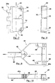
- the invention proposes a remarkable nozzle flap in that it is consisting of a hollow frustoconical body and transversely flattened following generators rectilinear geometries, the body forming a wall thin of substantially constant thickness E, this wall being divided transversely into four parts adjacent to: a so-called trapezoidal and flat wall "Hot”, a so-called trapezoidal and flat wall "Cold” parallel to the hot wall and two walls symmetrical sides laterally connecting the wall cold and the hot wall, the wall having a continuous inner surface with a radius of curvature at least equal to 2xE, the wall being of material refractory composite made of reinforcing fibers continuous and cross drowned refractory material in a matrix of material also refractory.
- Double-walled nozzle shutters made of composite material do not seem to have been proposed in art. The reasons are probably to search because of the finding that the gradients of temperature also exist and that the risks of vitreous rupture are not diminished; and in difficulty of shaping such a nozzle flap with the techniques specific to composite materials.
- this shutter has at one end an articular element said “upstream” attached to an insert called “upstream” penetrating into the cavity of the shutter, the insert being held by screws against the cold wall, the cold wall being taken locally sandwiched between the heads of screw and the upstream insert, the screws passing through the wall cold and screwing into the upstream insert.
- the component has an element articulation said "downstream” integral with an insert said “Downstream” and a connecting rod clevis applied against the cold wall outside the flap, the connecting rod being located on the middle part of the shutter, the insert downstream extending inside the flap until under the end cap, the downstream insert being fixed against the cold wall by at least three screws whose head is at the outside of the shutter, the screws passing through the wall cold and coming to screw into the downstream insert, one three screws also passing through the connecting rod and to keep it against the cold wall.
- the thermal insulation offered by the shutter also depends on its thickness, that is to say the width of the side walls. It is advantageous that these do not just include portions rounded but also flat portions to offer a greater barrier to overheating.
- the mechanical strength of the shutter must sometimes be strengthened.
- the component will then include ribs joining the trapezoidal and flat walls by rounded portions having a radius of curvature at least equal to 2xE. These ribs are also in matter refractory composite and are only responsible for a low heat leakage to the cold wall.
- An important aspect of the invention is the method of manufacturing such a nozzle flap. he includes the steps to create an edged texture continuous interwoven refractory fibers, in tension of the texture around rigid sections and porous, opposite and curved with convexities directed in divergent directions and having radius of curvature at least equal to 2xE, E being the thickness of the texture, and deposition of a matrix refractory by vapor phase deposition on the texture and through the profiles.
- a variant of this process, used for build a ribbed flap that we talked about above, includes the steps of creating a plurality textures with continuous edges of refractory fibers intertwined, tensioning textures around pairs of rigid and porous profiles, opposed and curved with convexities directed into divergent directions for each of the walls, the profiles respectively having radii of curvature at less than 2xE, where E is the thickness of one of the textures that is stretched over the profile, and deposition of a refractory matrix by vapor phase deposition on the textures and through the profiles, the textures with superimposed portions and the matrix being continuous through said superimposed portions.
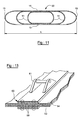
- Part 1 consists of a cylindrical body 10 transversely flattened whose a geometric generator is illustrated with reference 11.
- the body 10 is constituted by a thin wall 12 of thickness E monobloc, that is to say in one piece.
- the wall 12 has four adjacent parts two to two according to a generator 11.
- the first part or hot wall 13 is flat and rectangular.
- the second part or cold wall 14 is flat, rectangular and opposite and parallel to the hot wall 13.
- the third and the fourth part are made by the walls lateral 15 and are convex, that is to say curved outwards.
- the wall 12 is in refractory composite material.
- this material consists of 18 refractory fibers continuous and crossed embedded in a matrix also refractory.
- the radius of curvature R of the inner surface 17 must be at least equal to twice the thickness E of the wall 12 to avoid the stress delamination of the fiber plies 18, that is to say the separation of the different layers by rupture of the matrix.
- the height H of flap is at least equal to six times the thickness E of the wall.
- Such a structure allows thin shutters whose width L1 is at least five times the height H.
- Part of the fibers 18a are globally parallel to each other.
- the fibers 18 are inclined at 45 ° with respect to generators 11.
- This configuration is more particularly used for a short body 12.
- the half of the fibers 18a crosses the other half of the fibers 18b at 90 °.
- the manufacture of the body 10 is made by the techniques well known to those skilled in the art.
- the fiber fabric can be a classic sheet.
- a multilayer fabric for example a so-called "2.5D" fabric disclosed by the US Patent 5,899,241 to Patent Priority French FR 2.759.096.
- the hot wall 13 is licked at least in part by the hot gas stream 4 propulsion while the cold wall 14 opposite the hot wall 13 is licked by a cold stream 5.
- the hot wall 13 expands with respect to the wall cold 14 but the tensile force that is so transmitted to the cold wall 14 transversely to the generators 11 is attenuated by the deformation of side walls 15 which therefore takes up part of this effort.
- Such a component therefore makes it possible to reduce substantially the tensile stresses caused by thermal gradients, which allows the use Refractory composite materials with vitreous rupture such as those mentioned above, which solves the problem.
- the subject of the present invention also the advantage of allowing the reduction of infrared signature of the nozzle in two ways.
- the cold wall 14 is better insulated thermally from the hot wall 13 because of the hollow structure of the shutter.
- Part 1 is equipped upstream 2 with an element upstream articulation joint 30 of the swiveling type integral with a upstream insert 31 consisting of three ribs 32 plus high than wide, of a connecting wall 33 transversely the ribs 32 between them and providing lateral rigidity, and two bosses 34.
- articulation element we mean the part of the joint that remains attached to the shutter when the joint is disassembled.
- the element 30 upstream articulation, the upstream insert 31 and its constituents so defined constitute a whole monobloc, that is to say in one piece.
- the upstream insert 31 is deposited in the inner cavity 16 upstream 2 of the flap 1.
- the upstream insert 31 is disposed in the interior cavity 16 upstream 2 of the shutter 1.
- the insert upstream 31 is held against the cold wall 14 by two screw 35 whose head is outside the shutter 1, these screw 35 passing through the cold wall 14 and coming screw in the bosses 34.
- the cold wall 14 is taken locally sandwiched between the heads of the screws 35 and the insert.
- the screws 35 are advantageously separated so that they are each positioned in the vicinity of a side wall 15 not to impose on the cold wall bending stresses transversely to generators 11, the forces being taken up by the angle formed by the cold wall 14 in the vicinity of the wall side 15 at this location and by this side wall 15.
- Part 1 is also equipped with a downstream articulation member 40 of the pivoting type connected to a downstream insert 41 and forming with it a set piece.
- the downstream articulation element 40 is deported outside the shutter on the side of the cold wall 14.
- the downstream articulation element 40 allows pivoting along a geometric axis 40a perpendicular to generators 11, parallel to the cold wall 14 and substantially in alignment with this cold wall 14.
- Part 1 is also equipped with a clevis connecting rod 42 applied against the cold wall 14 to the outside of the flap 1, the connecting rod cap 42 being located on the middle part of part 1 to equal distance from the side walls 15.
- the downstream insert 41 is extended inside from flap 1 to under the connecting rod yoke 42.
- the insert downstream 41 is fixed against the cold wall 14 by three screw 43 whose head is outside the shutter 1, the screw passing through the cold wall 14 and screwing each in a boss 44 of the downstream insert 41.
- Two three screws 43 are close to the element downstream articulation 40 and spread to be also positioned each in the vicinity of a wall this is for the reasons already stated in the case of the screws 35 fixing the upstream insert 31.
- the third screw 43 also passes through the connecting rod yoke 42 and keeps it against the cold wall. understands that the connecting rod cap 42 allows in exploitation to maneuver the flap 1 by via a rod not shown.
- the downstream insert 41 is also extended upstream 2 by a fork 45 whose branches pass under the connecting rod cap 42 to prevent the cold wall 14 to flex under the force transmitted by the connecting rod clevis 42 to the cold wall 14, the fork 45 resuming this effort.
- the surface of the insert downstream 41 referenced 46 in Figure 9 is in contact with the cold wall 14 and complementary shape, so flat in practice.
- part 1 is extended downstream 3 by a tip 45 which is a extension of the wall 12 and more precisely the hot wall 13 and side walls 15, this extension always according to the generators 11.
- the downstream end 45 allows channel the warm stream 4 further downstream 3 and thus protect the downstream articulation element 40 since the downstream endpiece 45 passes between the articulation element downstream 40 and the hot stream 4.
- the present invention has the advantage in operation of isolating completely the fixing screws 35, 43 of the hot flow 4 since the hot wall 13 passes between the screws and the hot flow, these screws necessarily remaining metallic.
- upstream articulation element 30 which is this time of swivel type according to a geometric axis 30a perpendicular to the generators 11, parallel to the hot and cold walls 13, 14 and at mid-distances from generators 11 defining the hot and cold walls 13, 14.
- This figure also shows the upstream insert 31 introduced into shutter 1 and fixed against the wall cold 14 by the two screws 35.
- downstream tip 45 constituted here by the downstream extension 3 of the downstream insert 41.
- the downstream end 45 is stiffened by ribs 50 planes and perpendicular to the geometric axis of pivoting 40a, the upstream portion of these ribs 50 being drilled according to the geometric axis of pivoting 40a and thus constituting the downstream articulation element 40.
- Stream 1 may have more generally a flattened frustoconical shape, the hot wall 13 and the cold wall 14 then being trapezoidal, of preferably but not necessarily isosceles, the walls lateral 15 being no longer parallel.
- the inserts upstream and downstream 31, 41 can be drilled in order to let a cold air flow through the shutter.
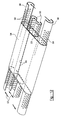
- the walls of the shutter 50 are first materialized by textures composed of the intercrossing of the refractory fibers. These textures here are two in number, one 53 being arranged in the other 54.
- a pair of tensioners is associated with each of the textures 53 and 54 to stretch them to form flat expanses between the profiles, which will give birth to the walls hot and cold.
- Tensioning profiles of the texture 53 have the reference 55, those of the texture 54 the 56.
- the profiles 55 and 56 of each pair are face and have curved sections with convexity directed outward, so that the textures 53, 54 take the form, rounded at least at their edges, of sidewalls 15 and ribs 51.
- the spacing the profile walls 55 and 56 are maintained by spacers 57 of any kind.
- profiles 55 and 56 are perforated or porous, the pores 58.
- the pairs of profiles 55 and 56 are arranged symmetrically to a common plane.
- Textures 53 and 54 thus take on a shape flattened sleeve. They touch each other by their faces planes between the tensioning profiles 55 and 56. It is note that they are formed in practice from sheets of fibers that have been folded and joined by edges opposed.
- the seal lines 59 thus obtained can be sewn or stapled. They can also be pressed between opposite elements of a fitting metal 60 advantageously carrying a clevis 61 of control rod. This is shown in Figure 13. Finally, the seal lines 59 may be adjacent or opposed. Better cohesion can be achieved by sewing or stapling together textures 53 and 54 where they join touch, without this being necessary. In all variants, the material composite is created by depositing the matrix material on the textures 53 and 54 by a deposit in phase of steam.
- the matter of the matrix is slowly entering the fiber network of textures 53 and 54 passing also by the pores 58, which therefore do not allow the tensioning profiles 55 and 56 to weaken the walls 15 and the ribs 51 by stopping the material deposit.
- a hardening of the composite can be achieved by oven heating. The same process is applied to manufacturing flaps without ribs, a single texture and a single wall of tensioning profiles being employed.
- the tensioning profiles 55 and 56 define therefore the shape of the side walls 15 and ribs 51, including rounded edges.
- the superposition of textures on part of the breadth of their portions planes gives a stronger wall thickness hot and cold 13 and 14 in the center. This thickness more large strengthens the flap 50 against bending around the tangential meaning. It has the disadvantage of a deposit more difficult from the matrix material to the heart of the stacking of textures, but that can be obtained by a gradual migration carried out by several stages densification.
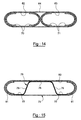
- Tensioners 70 and 71 are used for three textures 62, 63 and 64, the last of which surrounds the other two, who are side by side.
- the profiles 70 extend the texture 62, and the profiles 71 the texture 63.
- the extreme profiles 70 and 71 of the alignment tend also the texture 64, and the two sections 60 and 61 intermediaries, directed towards each other, make touch the inner ends of the textures 62 and 63.
- the same manufacturing process will give a component of nozzle having a central rib particularly strong since it will join the hot and cold walls by pairs of rounded edges.
- the nozzle flap will be formed essentially from a first texture 75, from texture-like shape 54 for example, and a inner texture 76 wavy and with two wings 77 on the sides of the hot wall 13, a strip 78 under the center of the cold wall 14, and two ribs oblique 79 joining the band 78 to the wings 77.
- the internal texture 76 can be stretched and densified partially separately to make it rigid before that the first texture 75 is threaded around her.
- a third texture 80, skirting side walls 15 and the cold wall 14 of a wing 77 to the other, can complete the structure of the component and reinforce the cold wall 14. It can be sewn or the internal texture 76.
- the densification of textures 75, 76 and 80 to form the nozzle flap is then undertaken as for other achievements, with a pair of tensioning profiles 81 at the ends, which are similar to tensioning profiles 56.
- Figure 16 illustrates a finishing mode of a ribbed nozzle flap, that of FIG. example, where we proceed to the finishing of the pieces of mechanical connection.
- the upstream insert 82 engaged in the shutter proper is fork-shaped and comprises a central tooth 83 engaged between the two ribs 51 and two lateral teeth 84 engaged between the ribs 51 and the side walls 15, and between them. It is completed by a plate 85 which encloses the cold wall 14 between it and the teeth 83 and 84. All these elements are provided with holes 86 of passage of unrepresented clamping screws, which ensure the tightening.
- the nozzle flaps may include radii of curvature more or less important in the limit shown here. Small radii of curvature are in general preferred.
- the sealing flaps 20 cover a smaller width of the hot wall 13 if the side walls 15 have small rounds of connection, and the thermal gradients of the wall hot 13 are reduced; and the nozzle flaps can come closer to each other in the state of closing of the nozzle since they are less wide: a bigger closure becomes possible.
- a particular arrangement of the shutters of nozzle comprises metal parts attached to the cold wall 14 and constructed of titanium. This metal is appreciated for its lightness in aeronautics and elsewhere, but it does not withstand heating well. It is however possible to obtain differences of temperature of 400 ° C between the hot and cold walls 13 and 14 (at 1000 ° C and 600 ° C for example) with the invention, which justifies its use for the fitting 60, the screed 61, etc.
Landscapes
- Engineering & Computer Science (AREA)
- Chemical & Material Sciences (AREA)
- Combustion & Propulsion (AREA)
- Mechanical Engineering (AREA)
- General Engineering & Computer Science (AREA)
- Food Science & Technology (AREA)
- Life Sciences & Earth Sciences (AREA)
- Turbine Rotor Nozzle Sealing (AREA)
- Furnace Housings, Linings, Walls, And Ceilings (AREA)
- Extrusion Moulding Of Plastics Or The Like (AREA)
- Filling Or Discharging Of Gas Storage Vessels (AREA)
- Chemical Vapour Deposition (AREA)
- Laminated Bodies (AREA)
- Structures Of Non-Positive Displacement Pumps (AREA)
- Thermal Insulation (AREA)
- Nonwoven Fabrics (AREA)
- Wing Frames And Configurations (AREA)
Abstract
Description
Claims (11)
- Volet de tuyère pour turbomoteur d'avion, caractérisé en ce qu'il est constitué d'un corps (10) tronconique creux et transversalement aplati suivant des génératrices géométriques (11) rectilignes, le corps (10) comprend une paroi (12) mince d'épaisseur sensiblement constante E, cette paroi (12) étant divisée transversalement en quatre parties adjacentes soit :une paroi (13) trapézoïdale et plane dite « chaude »,une paroi (14) trapézoïdale et plane dite « froide » parallèle à la paroi chaude (13) et deux parois latérales (15) symétriques reliant latéralement la paroi froide (13) et la paroi (14),la paroi (12) comportant une surface intérieure (17) continue avec un rayon de courbure au moins égal à 2xE, la paroi (12) étant en matériau composite réfractaire constitué de fibres de renfort (18) continues et croisées en matériau réfractaire, les fibres de renfort (18) étant noyées dans une matrice en matériau également réfractaire.
- Volet selon la revendication 1, caractérisé en ce qu'il comporte à une extrémité un élément d'articulation (30) dit « amont » solidaire d'un insert (31) dit « amont » pénétrant dans la cavité 16 du volet 1, l'insert (31) étant tenu par des vis (35) contre la paroi froide (14), la paroi froide (14) étant prise localement en sandwich entre les têtes des vis (35) et l'insert amont (31), les vis (35) traversant la paroi froide (14) et se vissant dans l'insert amont (31).
- Volet selon la revendication 1, caractérisé en ce qu'il comporte un élément d'articulation (40) dit « aval » solidaire d'un insert 41 dit « aval » et une chape de bielle (42) appliquée contre la paroi froide (14) à l'extérieur du volet (1), la chape de bielle (42) étant située sur la partie médiane du volet (1), l'insert aval (41) se prolongeant à l'intérieur du volet (1) jusque sous la partie médiane du volet (1) jusque sous la chape de bielle (42), l'insert aval (41) étant fixé contre la paroi froide (14) par au moins trois vis (43) dont la tête est à l'extérieur du volet (1), les vis (43) traversant la paroi froide (14) et venant se visser dans l'insert aval (41), l'une des trois vis (43) traversant également la chape de bielle (42) et permet de la maintenir contre la paroi froide (14).
- Volet selon l'une quelconque des revendications 1 à 3, caractérisé en ce que les parois latérales (15) comprennent des portions planes reliées aux parois trapézoïdales et planes (13, 14) par des portions arrondies ayant le rayon de courbure au moins égal à 2xE à la surface intérieure (17).
- Volet selon l'une quelconque des revendications 1 à 4, caractérisé en ce qu'il comprend des nervures joignant les parois trapézoïdales et planes (13, 14), essentiellement parallèles aux parois latérales et se raccordant aux parois trapézoïdales et planes par des portions arrondies ayant un rayon de courbure au moins égal à 2xE à une surface intérieure.
- Volet selon la revendication 5, caractérisé en ce que les parois trapézoïdales et planes ont des épaisseurs croissant des parois latérales à une bande centrale.
- Procédé de fabrication d'un volet de tuyère comprenant les étapes de création d'une texture à bords continus de fibres réfractaires entrecroisées, de mise en tension de la texture autour de profilés rigides et poreux, opposés et incurvés avec des convexités dirigées dans des directions divergentes et ayant des rayons de courbure au moins égaux à 2xE à une surface intérieure, E étant l'épaisseur de la texture, et de dépôt d'une matrice réfractaire par dépôt en phase de vapeur sur la texture et à travers les profilés.
- Procédé de fabrication d'un volet de tuyère comprenant les étapes de création d'une pluralité de textures (53, 54, 62, 63, 64) à bords continus de fibres réfractaires entrecroisées, de mise en tension des textures autour de paires de profilés rigides et poreux (55, 56, 70, 71), opposés et incurvés avec des convexités dirigées dans des directions divergentes pour chacune des paires, les profilés ayant des rayons de courbures au moins égaux à 2xE, E étant l'épaisseur d'une des textures qui est tendue sur les profilés, et de dépôt d'une matrice réfractaire par dépôt en phase de vapeur sur les textures et à travers les profilés, les textures ayant des portions superposées et la matrice étant continue à travers lesdits portions superposées.
- Procédé de fabrication selon la revendication 8, caractérisé en ce que les paires de profilés sont disposées symétriquement à un plan commun, et les portions superposées de textures sont planes et situées entre les paires de profilés.
- Procédé de fabrication selon l'une quelconque des revendications 8 ou 9, caractérisé en ce qu'il comprend une étape de liaison de textures entre elles aux portions superposées avant le dépôt en phase de vapeur.
- Procédé de fabrication selon l'une quelconque des revendications 7 à 10, caractérisé en ce que la texture ou les textures sont rendues continues par pliage d'une feuille de fibres entrecroisées, raccordement de deux bords opposés de la feuille et liaison desdits deux bords par une pièce de liaison (60).
Applications Claiming Priority (2)
| Application Number | Priority Date | Filing Date | Title |
|---|---|---|---|
| FR0350177 | 2003-05-26 | ||
| FR0350177A FR2855557B1 (fr) | 2003-05-26 | 2003-05-26 | Volet de tuyere a duree de vie augmentee pour turbomoteurs d'avion. |
Publications (2)
| Publication Number | Publication Date |
|---|---|
| EP1482158A1 true EP1482158A1 (fr) | 2004-12-01 |
| EP1482158B1 EP1482158B1 (fr) | 2009-01-14 |
Family
ID=33104530
Family Applications (1)
| Application Number | Title | Priority Date | Filing Date |
|---|---|---|---|
| EP04102264A Expired - Lifetime EP1482158B1 (fr) | 2003-05-26 | 2004-05-24 | Volet de tuyère à durée de vie augmentée pour turbomoteurs d'avion |
Country Status (15)
| Country | Link |
|---|---|
| US (1) | US6964169B2 (fr) |
| EP (1) | EP1482158B1 (fr) |
| JP (1) | JP4116984B2 (fr) |
| KR (1) | KR101124011B1 (fr) |
| CN (1) | CN100371580C (fr) |
| AU (1) | AU2004202297B2 (fr) |
| BR (1) | BRPI0401835B1 (fr) |
| CA (1) | CA2467842C (fr) |
| DE (1) | DE602004019013D1 (fr) |
| ES (1) | ES2318240T3 (fr) |
| FR (1) | FR2855557B1 (fr) |
| RU (1) | RU2358136C2 (fr) |
| TW (1) | TWI323714B (fr) |
| UA (1) | UA85369C2 (fr) |
| ZA (1) | ZA200403904B (fr) |
Cited By (1)
| Publication number | Priority date | Publication date | Assignee | Title |
|---|---|---|---|---|
| WO2024161077A1 (fr) * | 2023-02-02 | 2024-08-08 | Safran Ceramics | Volet froid de tuyere d'arriere-corps |
Families Citing this family (14)
| Publication number | Priority date | Publication date | Assignee | Title |
|---|---|---|---|---|
| FR2894500B1 (fr) * | 2005-12-08 | 2009-07-10 | Snecma Sa | Assemblage par brasage d'une piece metallique avec une piece en materiau ceramique |
| FR2894498B1 (fr) * | 2005-12-08 | 2009-07-10 | Snecma Sa | Assemblage par brasage entre une piece metallique a base de titane et une piece en materiau ceramique a base de carbure de silicium (sic) et/ou de carbone |
| FR2894499B1 (fr) * | 2005-12-08 | 2011-04-01 | Snecma | Assemblage entre une piece metallique et une piece en materiau ceramique a base de sic et/ou de c |
| US7617685B2 (en) * | 2006-09-29 | 2009-11-17 | United Technologies Corporation | Quick change fastener system for attaching liner bracket to convergent flap and seal in turbine nozzle |
| US7685825B2 (en) * | 2006-09-29 | 2010-03-30 | United Technologies Corporation | Axially split nozzle liner for convergent nozzle |
| FR2914707B1 (fr) * | 2007-04-05 | 2009-10-30 | Snecma Propulsion Solide Sa | Procede d'assemblage avec recouvrement de deux pieces ayant des coefficients de dilatation differents et assemblage ainsi obtenu |
| US8043690B2 (en) | 2008-04-21 | 2011-10-25 | The Boeing Company | Exhaust washed structure and associated composite structure and method of fabrication |
| US9932845B2 (en) * | 2011-06-30 | 2018-04-03 | United Technologies Corporation | Impingement cooled nozzle liner |
| FR2979575B1 (fr) * | 2011-09-05 | 2013-09-20 | Snecma | Procede et dispositif de fabrication d'une piece cylindrique en materiau composite |
| US20140238027A1 (en) * | 2012-12-21 | 2014-08-28 | United Technologies Corporation | Thermally compliant dual wall liner for a gas turbine engine |
| EP3097301B1 (fr) * | 2014-01-24 | 2018-05-02 | United Technologies Corporation | Volet divergent |
| US10352273B2 (en) | 2016-11-08 | 2019-07-16 | Rohr, Inc. | Track beam with composite lug |
| CN107618654B (zh) * | 2017-08-03 | 2021-03-30 | 南京航空航天大学 | 飞行器姿态控制系统及其控制方法、控制喷嘴 |
| CN113530705A (zh) * | 2021-08-18 | 2021-10-22 | 中国航发贵阳发动机设计研究所 | 一种航空发动机可调喷管外调节片收放限位装置 |
Citations (4)
| Publication number | Priority date | Publication date | Assignee | Title |
|---|---|---|---|---|
| US4196856A (en) * | 1977-11-25 | 1980-04-08 | The Boeing Company | Variable geometry convergent divergent exhaust nozzle |
| US4637550A (en) * | 1985-10-01 | 1987-01-20 | The United States Of America As Represented By The Secretary Of The Air Force | Dual material exhaust nozzle flap |
| US5000386A (en) * | 1989-07-03 | 1991-03-19 | General Electric Company | Exhaust flaps |
| US5034172A (en) * | 1988-10-14 | 1991-07-23 | Societe Europeenne De Propulsion | Process for the manufacture of composite components comprising a web and a reinforcement structure |
Family Cites Families (6)
| Publication number | Priority date | Publication date | Assignee | Title |
|---|---|---|---|---|
| US5553455A (en) * | 1987-12-21 | 1996-09-10 | United Technologies Corporation | Hybrid ceramic article |
| FR2664585B1 (fr) * | 1990-07-13 | 1993-08-06 | Europ Propulsion | Structures refractaires refroidies et procede pour leur fabrication. |
| EP0750107B1 (fr) * | 1995-06-21 | 1999-10-27 | Volvo Aero Corporation | Volet pour une tuyère de propulsion |
| US5992140A (en) * | 1997-06-24 | 1999-11-30 | Sikorsky Aircraft Corporation | Exhaust nozzle for suppressing infrared radiation |
| RU2142571C1 (ru) * | 1997-09-22 | 1999-12-10 | Государственное унитарное предприятие "Завод им.В.Я.Климова" ВПК "Мапо" | Регулируемое сопло авиационного двигателя с отклоняемым вектором тяги |
| FR2919897B1 (fr) * | 2007-08-08 | 2014-08-22 | Snecma | Secteur de distributeur de turbine |
-
2003
- 2003-05-26 FR FR0350177A patent/FR2855557B1/fr not_active Expired - Fee Related
-
2004
- 2004-05-19 CA CA2467842A patent/CA2467842C/fr not_active Expired - Lifetime
- 2004-05-20 ZA ZA2004/03904A patent/ZA200403904B/en unknown
- 2004-05-20 US US10/849,019 patent/US6964169B2/en not_active Expired - Lifetime
- 2004-05-21 JP JP2004151505A patent/JP4116984B2/ja not_active Expired - Lifetime
- 2004-05-24 EP EP04102264A patent/EP1482158B1/fr not_active Expired - Lifetime
- 2004-05-24 ES ES04102264T patent/ES2318240T3/es not_active Expired - Lifetime
- 2004-05-24 DE DE602004019013T patent/DE602004019013D1/de not_active Expired - Lifetime
- 2004-05-25 CN CNB2004100425968A patent/CN100371580C/zh not_active Expired - Lifetime
- 2004-05-25 KR KR1020040037369A patent/KR101124011B1/ko not_active Expired - Lifetime
- 2004-05-25 RU RU2004116014/06A patent/RU2358136C2/ru active
- 2004-05-25 UA UA20040503972A patent/UA85369C2/ru unknown
- 2004-05-26 TW TW093114967A patent/TWI323714B/zh not_active IP Right Cessation
- 2004-05-26 BR BRPI0401835-4A patent/BRPI0401835B1/pt not_active IP Right Cessation
- 2004-05-26 AU AU2004202297A patent/AU2004202297B2/en not_active Expired
Patent Citations (4)
| Publication number | Priority date | Publication date | Assignee | Title |
|---|---|---|---|---|
| US4196856A (en) * | 1977-11-25 | 1980-04-08 | The Boeing Company | Variable geometry convergent divergent exhaust nozzle |
| US4637550A (en) * | 1985-10-01 | 1987-01-20 | The United States Of America As Represented By The Secretary Of The Air Force | Dual material exhaust nozzle flap |
| US5034172A (en) * | 1988-10-14 | 1991-07-23 | Societe Europeenne De Propulsion | Process for the manufacture of composite components comprising a web and a reinforcement structure |
| US5000386A (en) * | 1989-07-03 | 1991-03-19 | General Electric Company | Exhaust flaps |
Cited By (2)
| Publication number | Priority date | Publication date | Assignee | Title |
|---|---|---|---|---|
| WO2024161077A1 (fr) * | 2023-02-02 | 2024-08-08 | Safran Ceramics | Volet froid de tuyere d'arriere-corps |
| FR3145587A1 (fr) * | 2023-02-02 | 2024-08-09 | Safran Ceramics | Volet froid de tuyère d'arrière-corps |
Also Published As
| Publication number | Publication date |
|---|---|
| BRPI0401835B1 (pt) | 2014-04-29 |
| KR101124011B1 (ko) | 2012-03-27 |
| FR2855557A1 (fr) | 2004-12-03 |
| ZA200403904B (en) | 2005-07-27 |
| DE602004019013D1 (de) | 2009-03-05 |
| RU2004116014A (ru) | 2005-11-20 |
| CN1538051A (zh) | 2004-10-20 |
| CN100371580C (zh) | 2008-02-27 |
| US6964169B2 (en) | 2005-11-15 |
| EP1482158B1 (fr) | 2009-01-14 |
| UA85369C2 (ru) | 2009-01-26 |
| KR20040101934A (ko) | 2004-12-03 |
| AU2004202297B2 (en) | 2009-07-30 |
| CA2467842A1 (fr) | 2004-11-26 |
| JP2004353668A (ja) | 2004-12-16 |
| TWI323714B (en) | 2010-04-21 |
| RU2358136C2 (ru) | 2009-06-10 |
| TW200505744A (en) | 2005-02-16 |
| JP4116984B2 (ja) | 2008-07-09 |
| BRPI0401835A (pt) | 2005-01-25 |
| FR2855557B1 (fr) | 2007-03-02 |
| AU2004202297A1 (en) | 2004-12-16 |
| CA2467842C (fr) | 2012-01-24 |
| ES2318240T3 (es) | 2009-05-01 |
| US20050005608A1 (en) | 2005-01-13 |
Similar Documents
| Publication | Publication Date | Title |
|---|---|---|
| EP1482158B1 (fr) | Volet de tuyère à durée de vie augmentée pour turbomoteurs d'avion | |
| EP2132730B1 (fr) | Procede de realisation d'une structure acoustiquement resistive, structure acoustiquement resistive ainsi obtenue et revetement utilisant une telle structure | |
| EP2578495B1 (fr) | Panneau pour le traitement acoustique intégrant des canaux d'air chaud et au moins une chambre de stabilisation | |
| CA2811477C (fr) | Procede de fabrication d'une piece et piece massive composite obtenue par ce procede | |
| EP2578496B1 (fr) | Panneau pour le traitement acoustique intégrant des canaux d'air chaud et au moins un canal annulaire | |
| EP1999020B1 (fr) | Structure pour levre d'entree d'air de nacelle a degivrage electrique comprenant une zone d'attenuation acoustique | |
| EP2391542B1 (fr) | Nacelle d'aeronef comprenant un systeme de traitement acoustique optimise | |
| CA2630715C (fr) | Procede de fabrication d'une chape sur un element structural en materiau composite, notamment une bielle | |
| EP2578842B1 (fr) | Nacelle d'aéronef comportant un dispositif d'alimentation en air chaud d'un panneau combinant les traitements acoustique et du givre | |
| CA2630763C (fr) | Procede de fabrication d'une bielle en materiau composite | |
| EP2393651B1 (fr) | Procédé de fabrication d'une structure a âmes alvéolaires pour une nacelle de turboréacteur | |
| EP2340142A1 (fr) | Assemblage de pieces en titane et en acier par soudage diffusion | |
| CA2478781A1 (fr) | Tuyere convergente divergente de turboreacteur | |
| EP3931435B1 (fr) | Système alvéolaire dilatable pour panneau sandwich | |
| FR2928715A1 (fr) | Procede d'assemblage de panneaux bord a bord | |
| FR2952032A1 (fr) | Nacelle d'aeronef comprenant un systeme de traitement acoustique optimise | |
| FR3044960A1 (fr) | Panneau pour nacelle de turboreacteur d’aeronef, comportant une protection thermique et une protection anti-feu | |
| FR3036061B1 (fr) | Panneau composite et nacelle de turboreacteur d’aeronef comprenant un tel panneau | |
| WO2009092938A2 (fr) | Opercule arrière déformable pour conteneur de missile, comportant un cadre de support aval | |
| WO2007006959A1 (fr) | Procede de fabrication de butees d'aeronef et butees de porte d'aeronef en materiau composite carbone | |
| WO2008142350A1 (fr) | Conduit d'échappement de véhicule automobile | |
| FR2728013A1 (fr) | Voiture de pale soudee par diffusion et son procede de fabrication | |
| FR2997127A1 (fr) | Aubes de turbine haute pression en composites a matrice ceramique | |
| EP2078919B1 (fr) | Opercule arrière déformable à lames élastiques pour conteneur de missile |
Legal Events
| Date | Code | Title | Description |
|---|---|---|---|
| PUAI | Public reference made under article 153(3) epc to a published international application that has entered the european phase |
Free format text: ORIGINAL CODE: 0009012 |
|
| AK | Designated contracting states |
Kind code of ref document: A1 Designated state(s): AT BE BG CH CY CZ DE DK EE ES FI FR GB GR HU IE IT LI LU MC NL PL PT RO SE SI SK TR |
|
| AX | Request for extension of the european patent |
Extension state: AL HR LT LV MK |
|
| 17P | Request for examination filed |
Effective date: 20050524 |
|
| AKX | Designation fees paid |
Designated state(s): DE ES FR GB IT SE |
|
| RAP1 | Party data changed (applicant data changed or rights of an application transferred) |
Owner name: SNECMA |
|
| GRAP | Despatch of communication of intention to grant a patent |
Free format text: ORIGINAL CODE: EPIDOSNIGR1 |
|
| GRAS | Grant fee paid |
Free format text: ORIGINAL CODE: EPIDOSNIGR3 |
|
| GRAA | (expected) grant |
Free format text: ORIGINAL CODE: 0009210 |
|
| AK | Designated contracting states |
Kind code of ref document: B1 Designated state(s): DE ES FR GB IT SE |
|
| REG | Reference to a national code |
Ref country code: GB Ref legal event code: FG4D Free format text: NOT ENGLISH |
|
| REF | Corresponds to: |
Ref document number: 602004019013 Country of ref document: DE Date of ref document: 20090305 Kind code of ref document: P |
|
| REG | Reference to a national code |
Ref country code: SE Ref legal event code: TRGR |
|
| REG | Reference to a national code |
Ref country code: ES Ref legal event code: FG2A Ref document number: 2318240 Country of ref document: ES Kind code of ref document: T3 |
|
| PLBE | No opposition filed within time limit |
Free format text: ORIGINAL CODE: 0009261 |
|
| STAA | Information on the status of an ep patent application or granted ep patent |
Free format text: STATUS: NO OPPOSITION FILED WITHIN TIME LIMIT |
|
| 26N | No opposition filed |
Effective date: 20091015 |
|
| PGFP | Annual fee paid to national office [announced via postgrant information from national office to epo] |
Ref country code: ES Payment date: 20120508 Year of fee payment: 9 |
|
| REG | Reference to a national code |
Ref country code: ES Ref legal event code: FD2A Effective date: 20140609 |
|
| PG25 | Lapsed in a contracting state [announced via postgrant information from national office to epo] |
Ref country code: ES Free format text: LAPSE BECAUSE OF NON-PAYMENT OF DUE FEES Effective date: 20130525 |
|
| REG | Reference to a national code |
Ref country code: FR Ref legal event code: PLFP Year of fee payment: 13 |
|
| REG | Reference to a national code |
Ref country code: FR Ref legal event code: PLFP Year of fee payment: 14 |
|
| REG | Reference to a national code |
Ref country code: FR Ref legal event code: CD Owner name: SAFRAN AIRCRAFT ENGINES Effective date: 20170719 |
|
| REG | Reference to a national code |
Ref country code: FR Ref legal event code: PLFP Year of fee payment: 15 |
|
| PGFP | Annual fee paid to national office [announced via postgrant information from national office to epo] |
Ref country code: IT Payment date: 20230420 Year of fee payment: 20 Ref country code: FR Payment date: 20230420 Year of fee payment: 20 Ref country code: DE Payment date: 20230419 Year of fee payment: 20 |
|
| PGFP | Annual fee paid to national office [announced via postgrant information from national office to epo] |
Ref country code: SE Payment date: 20230419 Year of fee payment: 20 |
|
| PGFP | Annual fee paid to national office [announced via postgrant information from national office to epo] |
Ref country code: GB Payment date: 20230420 Year of fee payment: 20 |
|
| REG | Reference to a national code |
Ref country code: DE Ref legal event code: R071 Ref document number: 602004019013 Country of ref document: DE |
|
| REG | Reference to a national code |
Ref country code: GB Ref legal event code: PE20 Expiry date: 20240523 |
|
| REG | Reference to a national code |
Ref country code: SE Ref legal event code: EUG |
|
| PG25 | Lapsed in a contracting state [announced via postgrant information from national office to epo] |
Ref country code: GB Free format text: LAPSE BECAUSE OF EXPIRATION OF PROTECTION Effective date: 20240523 |
|
| PG25 | Lapsed in a contracting state [announced via postgrant information from national office to epo] |
Ref country code: GB Free format text: LAPSE BECAUSE OF EXPIRATION OF PROTECTION Effective date: 20240523 |