EP1482088A1 - Abstütz- bzw. Abstreifeinrichtung für Siebbandanlagen - Google Patents
Abstütz- bzw. Abstreifeinrichtung für Siebbandanlagen Download PDFInfo
- Publication number
- EP1482088A1 EP1482088A1 EP03450243A EP03450243A EP1482088A1 EP 1482088 A1 EP1482088 A1 EP 1482088A1 EP 03450243 A EP03450243 A EP 03450243A EP 03450243 A EP03450243 A EP 03450243A EP 1482088 A1 EP1482088 A1 EP 1482088A1
- Authority
- EP
- European Patent Office
- Prior art keywords
- support
- transverse webs
- recesses
- parts
- strips
- Prior art date
- Legal status (The legal status is an assumption and is not a legal conclusion. Google has not performed a legal analysis and makes no representation as to the accuracy of the status listed.)
- Granted
Links
- 238000006073 displacement reaction Methods 0.000 claims description 2
- 238000004026 adhesive bonding Methods 0.000 description 1
- 230000002950 deficient Effects 0.000 description 1
- 238000004519 manufacturing process Methods 0.000 description 1
Images



Classifications
-
- D—TEXTILES; PAPER
- D21—PAPER-MAKING; PRODUCTION OF CELLULOSE
- D21F—PAPER-MAKING MACHINES; METHODS OF PRODUCING PAPER THEREON
- D21F1/00—Wet end of machines for making continuous webs of paper
- D21F1/48—Suction apparatus
- D21F1/52—Suction boxes without rolls
- D21F1/523—Covers thereof
-
- D—TEXTILES; PAPER
- D21—PAPER-MAKING; PRODUCTION OF CELLULOSE
- D21F—PAPER-MAKING MACHINES; METHODS OF PRODUCING PAPER THEREON
- D21F1/00—Wet end of machines for making continuous webs of paper
- D21F1/48—Suction apparatus
- D21F1/483—Drainage foils and bars
Definitions
- the subject invention relates to a supporting or stripping device, which is assigned to the screen belt located in a paper-making plant is and which or the like on a support frame. fixed, transverse aligned to the direction of movement of the wire belt support or squeegee having.
- Known such support or stripping means are on with a Support frame or the like. attached support or squeegee formed.
- the Attachment of the support or squeegee to the support frame is done either detachable, e.g. by means of screwing, or not directly detachable, e.g. by gluing.
- the present invention is therefore based on the object, a supporting or to provide stripping, in which the support or squeegee on the one hand the requirements of the operation according to rigid are fixed and in which, however, the attachment of the support or squeegee in a simple manner can be produced and solved.
- this will According to the invention achieved in that the support frame or the like.
- the transverse webs and the support and squeegee formed with mutually associated recesses and projections are, by means of which the transverse webs and the support or squeegee connectable to each other and by displacement of the two parts of the transverse webs are clamped against each other.
- support or squeegee are formed with support strips, by means of which they are provided in the two parts of the transverse webs Recesses with the transverse webs are detachable.
- support or squeegee be formed with recesses, by means of which they over at the two Parts of the transverse webs provided projections with the transverse webs detachable are.
- the recesses of the parts of the transverse webs and the grooves or Recesses of the support or squeegee be undercut and can each associated support strips of the support or squeegee or the projections of the two parts of the transverse webs to their free ends be widening out.
- the two parts of the transverse webs are adjacent to each other and are their recesses or projections against each other with respect to their Offset end faces, whereby the coupled support or squeegees and transverse webs in the attachment of the transverse webs to the two support beams by adjusting the two parts of the transverse webs against each other be jammed.
- one of the two parts of the transverse webs formed as a plate which along one of the side edges with recesses or projections is formed, and is the other of the two Parts of the transverse webs formed as a double-walled plate, which is the first Surrounding plate on its two outer sides and which also along one their side edges with the recesses or projections of the first part associated recesses or projections is formed.
- Figures 1 and 2 is a support or stripping device according to the invention shown, which serves in a plant containing a sieve belt be provided for paper production, wherein the screen belt along the Surfaces of support or squeegee is moved.
- These support or stripping device has a frame-shaped carrier 1 for supporting or squeegee 4 on.
- the support or squeegee 4 are at their Top provided with wear strips 41. At their bottom they are as Dovetail-shaped support strips 42 formed.
- the carrier 1 consists from two parallel to the squeegee 4 aligned support beams 2 and 2a, which means of these transversely oriented webs 3 together are connected, that they screwed by means of screws 21 with the webs 3 are.
- the webs 3 each consist of two parts 31 and 32, which at their upper edges with undercut recesses 33 and 34 are formed are, in these recesses 33 and 34, which are associated with each other are, the support strips 42 of the support or squeegee 4 are used.
- the web portions 31 are further associated with the screws 21 holes 37 trained.
- a screen belt 5 is shown, which is guided over the support or squeegee 4.
- the two web portions 31 and 32 are shown in relation to FIG. 1 enlarged scale.
- the recesses 33 and 34 provided in the web parts 31 and 32 are slightly offset with respect to the end faces of the web parts 31 and 32, when the recesses 33 and 34 are aligned with one another. on one of the two sides of the web portion 32 projects beyond the web portion 31 and on the other side of the web portion 31 protrudes beyond the web portion 32.
- This mutual position of the two web portions 31 and 32 then occurs as soon as the support or wiper strips 4 have been inserted into the recesses 33 and 34.
- the recesses 33 and 34 are dimensioned so that in this the support or squeegee 4 with play and thus without significant resistance are displaced.
- the faces of the web portions 31 a and 32a slightly offset from each other.
- the rigid attachment of the support or squeegee 4a and 4b also takes place in that by the connection of the Longitudinal beams 2 and 2a with the two web portions 31 a and 32 a the web parts 31a and 32a are shifted from each other, whereby their projections 35 and 36 jammed within the grooves 43 and the recesses 44 become.
Landscapes
- Paper (AREA)
- Cleaning Implements For Floors, Carpets, Furniture, Walls, And The Like (AREA)
- Prostheses (AREA)
- Threshing Machine Elements (AREA)
- Nozzles For Electric Vacuum Cleaners (AREA)
- Filtration Of Liquid (AREA)
- Belt Conveyors (AREA)
- Screen Printers (AREA)
- Preliminary Treatment Of Fibers (AREA)
- Structure Of Belt Conveyors (AREA)
- Lining Or Joining Of Plastics Or The Like (AREA)
- Drying Of Solid Materials (AREA)
Abstract
Description
- Fig.1
- eine erfindungsgemäße Abstütz- bzw. Abstreifeinrichtung, in auseinandergezogener, axonometrischer Darstellung;
- Fig.2
- die Abstütz- und Abstreifeinrichtung nach Fig.1, in axonometrischer Darstellung;
- Fig.2a
- die Einrichtung nach Fig.2, in Seitenansicht;
- Fig.3
- einen Bestandteil gemäß Fig.2 in auseinandergezogener, axonometrischer Darstellung sowie in gegenüber Fig.1 vergrößertem Maßstab;
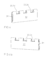
- Fig.4, Fig.4a
- den Bestandteil gemäß Fig.3, in zwei axonometrischen Darstellungen; sowie
- Fig..5
- eine Ausführungsvariante von Bestandteilen einer erfindungsgemäßen Abstütz- und Abstreifeinrichtung, in axonometrischer Darstellung.
In Fig.3 sind die beiden Stegteile 31 und 32 in gegenüber Fig. 1 vergrößertem Maßstab dargestellt.
Wie dies weiters aus den Fig.4 und 4a ersichtlich ist, sind die in den Stegteilen 31 und 32 vorgesehenen Ausnehmungen 33 und 34 insoferne gegenüber den Stirnflächen der Stegteile 31 und 32 geringfügig versetzt, als dann, wenn die Ausnehmungen 33 und 34 miteinander fluchten, auf einer der beiden Seiten der Stegteil 32 den Stegteil 31 überragt und auf der anderen Seite der Stegteil 31 über den Stegteil 32 hinausragt. Diese gegenseitige Lage der beiden Stegteile 31 und 32 tritt dann ein, sobald die Abstütz- bzw. Abstreifleisten 4 in die Ausnehmungen 33 und 34 eingesetzt worden sind. Die Ausnehmungen 33 und 34 sind so dimensioniert, daß in diesen die Abstütz- bzw. Abstreifleisten 4 mit Spiel und somit ohne maßgeblichen Widerstand verschiebbar sind.
Claims (8)
- Abstütz- bzw. Abstreifeinrichtung, welche dem in einer Anlage zur Papiererzeugung befindlichem Siebband (5) zugeordnet ist und welche an einem Tragrahmen (1) od.dgl. fest angeordnete, quer zur Bewegungsrichtung des Siebbandes (5) ausgerichtete Abstütz- bzw. Abstreifleisten (4, 4a, 4b) aufweist, dadurch gekennzeichnet, dass der Tragrahmen (1) od.dgl. zwei parallel zu den Abstütz- bzw. Abstreifleisten (4, 4a, 4b) ausgerichtete Tragbalken (2, 2a) und zwischen diesen befindliche und an diesen befestigbare zweiteilige Querstege (3, 3a) aufweist, wobei einerseits die Querstege (3, 3a) und andererseits die Abstütz- und Abstreifleisten (4, 4a, 4b) mit einander zugeordneten Ausnehmungen (33, 34, 43, 44) und Vorsprüngen (35, 36, 42) ausgebildet sind, mittels welcher die Querstege (3, 3a) und die Abstütz- bzw. Abstreifleisten (4, 4a, 4b) miteinander verbindbar und durch Verschiebung der beiden Teile (31, 32, 31 a, 32a) der Querstege (3, 3a) gegeneinander verklemmbar sind.
- Abstütz- bzw. Abstreifeinrichtung nach Patentanspruch 1, dadurch gekennzeichnet, dass Abstütz- bzw. Abstreifleisten (4) mit Tragleisten (42) ausgebildet sind, mittels welcher sie über in den beiden Teilen (31, 32) der Querstege (3) vorgesehenen Ausnehmungen (33, 34) mit den Querstegen (3) kuppelbar sind.
- Abstütz- bzw. Abstreifeinrichtung nach Patentanspruch 1, dadurch gekennzeichnet, dass Abstütz- bzw. Abstreifleisten (4a) mit Nuten (43) ausgebildet sind, mittels welcher sie über an den beiden Teilen (31a, 32a) der Querstege (3a) vorgesehenen Vorsprüngen (35, 36) mit den Querstegen (3a) kuppelbar sind.
- Abstütz- bzw. Abstreifeinrichtung nach Patentanspruch 3, dadurch gekennzeichnet, dass Abstütz- bzw. Abstreifleisten (4b) mit Ausnehmungen (44) ausgebildet sind, mittels welcher sie über an den beiden Teilen (31a, 32a) der Querstege (3a) vorgesehenen Vorsprüngen (35, 36) mit den Querstegen (3a) kuppelbar sind.
- Abstütz- bzw. Abstreifeinrichtung nach einem der Patentansprüche 1 bis 4, dadurch gekennzeichnet, dass die Ausnehmungen (33, 34) der Teile (31, 32) der Querstege (3) und die Nuten (43) bzw. Ausnehmungen (44) der Abstütz- bzw. Abstreifleisten (4a, 4b) hinterschnitten sind und dass die jeweils zugeordneten Tragleisten (42) der Abstütz- bzw. Abstreifleisten (4) bzw. die Vorsprünge (35, 36) der beiden Teile (31a, 32a) der Querstege (3a) sich zu ihren freien Enden hin erweiternd ausgebildet sind.
- Abstütz- bzw. Abstreifeinrichtung nach einem der Patentansprüche 1 bis 5, dadurch gekennzeichnet, daß die beiden Teile (31, 32, 31a, 32a) der Querstege (3, 3a) aneinander liegen und daß deren Ausnehmungen (33, 34) bzw. Vorsprünge (35, 36) gegeneinander in Bezug auf deren Stirnflächen versetzt sind, wodurch die miteinander gekuppelten Abstütz- bzw. Abstreifleisten (4, 4a, 4b) und Querstege (3, 3a) bei der Befestigung der Querstege (3, 3a) an den beiden Tragbalken (2, 2a) durch Verstellung der beiden Teile (31, 32, 31a, 32a) der Querstege (3, 3a) gegeneinander verklemmt werden.
- Abstütz- bzw. Abstreifeinrichtung nach einem der Patentansprüche 1 bis 6, dadurch gekennzeichnet, daß einer der beiden Teile (31, 31 a) der Querstege (3, 3a) als Platte ausgebildet ist, welche längs einer der Seitenkanten mit Ausnehmungen (33) bzw. Vorsprüngen (35) ausgebildet ist, und daß der andere der beide Teile (32, 32a) der Querstege (3, 3a) als doppelwandige Platte ausgebildet ist, welche die erste Platte (31, 31a) an ihren beiden Außenseiten umgibt und welche gleichfalls längs einer ihrer Seitenkante mit den Ausnehmungen (33) bzw. Vorsprüngen (35) des ersten Teiles (31, 31a) zugeordneten Ausnehmungen (34) bzw. Vorsprüngen (36) ausgebildet ist.
- Abstütz- bzw. Abstreifeinrichtung nach Patentanspruch 7, dadurch gekennzeichnet, daß die zweiten Teile (32, 32a) der Querstege (3, 3a) im Querschnitt U-förmig ausgebildet sind, wobei sie im Bereich ihrer Stege mit den Ausnehmungen (34) bzw. mit den Vorsprüngen (36) ausgebildet sind.
Priority Applications (1)
| Application Number | Priority Date | Filing Date | Title |
|---|---|---|---|
| AT03450243T ATE309408T1 (de) | 2003-05-28 | 2003-10-29 | Abstütz- bzw. abstreifeinrichtung für siebbandanlagen |
Applications Claiming Priority (2)
| Application Number | Priority Date | Filing Date | Title |
|---|---|---|---|
| AT8272003 | 2003-05-28 | ||
| AT0082703A AT413392B (de) | 2003-05-28 | 2003-05-28 | Abstütz- bzw. abstreifeinrichtung für siebbandanlagen |
Publications (2)
| Publication Number | Publication Date |
|---|---|
| EP1482088A1 true EP1482088A1 (de) | 2004-12-01 |
| EP1482088B1 EP1482088B1 (de) | 2005-11-09 |
Family
ID=33102758
Family Applications (1)
| Application Number | Title | Priority Date | Filing Date |
|---|---|---|---|
| EP03450243A Expired - Lifetime EP1482088B1 (de) | 2003-05-28 | 2003-10-29 | Abstütz- bzw. Abstreifeinrichtung für Siebbandanlagen |
Country Status (9)
| Country | Link |
|---|---|
| US (1) | US7198697B2 (de) |
| EP (1) | EP1482088B1 (de) |
| JP (1) | JP4115948B2 (de) |
| CN (1) | CN1280478C (de) |
| AT (2) | AT413392B (de) |
| BR (1) | BRPI0400179B1 (de) |
| CA (1) | CA2456751C (de) |
| DE (1) | DE50301617D1 (de) |
| ES (1) | ES2248724T3 (de) |
Cited By (1)
| Publication number | Priority date | Publication date | Assignee | Title |
|---|---|---|---|---|
| EP3211134A1 (de) * | 2016-02-29 | 2017-08-30 | Valmet Technologies, Inc. | Entwässerungsvorrichtung für eine fasernetzmaschine |
Families Citing this family (5)
| Publication number | Priority date | Publication date | Assignee | Title |
|---|---|---|---|---|
| US7641769B2 (en) * | 2006-10-17 | 2010-01-05 | Nichiha Corporation | Suction box and dehydrator with pressurization and forming machine using thereof |
| WO2008147766A1 (en) * | 2007-05-23 | 2008-12-04 | Astenjohnson, Inc. | Papermaking machine dewatering blade incorporating attachment mechanism |
| US10329093B2 (en) * | 2015-11-16 | 2019-06-25 | Laitram, L.L.C. | Conveyor bracket |
| CN112211027A (zh) * | 2020-10-12 | 2021-01-12 | 广东鸿铭智能股份有限公司 | 一种五联片卡纸的校位装置 |
| AT524317B1 (de) * | 2021-06-08 | 2022-05-15 | Bartelmuss Ing Klaus | Abstreifleiste und Bausatz zur Verwendung in einer Anlage zur Erzeugung einer Papierbahn |
Citations (3)
| Publication number | Priority date | Publication date | Assignee | Title |
|---|---|---|---|---|
| FR1423574A (fr) * | 1958-03-28 | 1966-01-03 | Feldmuehle Ag | Table de fabrication pour une machine à papier |
| US4443298A (en) * | 1982-03-08 | 1984-04-17 | Thorp Benjamin A | Controlled turbulence hydrofoil blade support member |
| DE19625375A1 (de) * | 1995-06-26 | 1997-01-02 | Jwi Ltd | Befestigungselement vom Klammertyp |
Family Cites Families (5)
| Publication number | Priority date | Publication date | Assignee | Title |
|---|---|---|---|---|
| US3194729A (en) * | 1961-10-23 | 1965-07-13 | Time Inc | Suction box top |
| DE2206857A1 (de) * | 1972-02-14 | 1973-08-23 | Voith Gmbh J M | Feststehende stuetzvorrichtung fuer das siebband einer entwaesserungsmaschine |
| IT1220862B (it) * | 1988-03-29 | 1990-06-21 | Awe Anti Wear Eng Srl | Coperchio di cassa aspirante con elementi costitutivi assiemabili |
| CA2036540C (en) * | 1990-05-04 | 2001-08-21 | Holt W. Simmons | Suction box apparatus with composite cover elements mounted in slots on cross braces |
| US5076894A (en) * | 1990-05-04 | 1991-12-31 | Simmons Holt W | Suction box apparatus with composite cover elements mounted in slots on cross braces |
-
2003
- 2003-05-28 AT AT0082703A patent/AT413392B/de not_active IP Right Cessation
- 2003-10-29 ES ES03450243T patent/ES2248724T3/es not_active Expired - Lifetime
- 2003-10-29 AT AT03450243T patent/ATE309408T1/de active
- 2003-10-29 EP EP03450243A patent/EP1482088B1/de not_active Expired - Lifetime
- 2003-10-29 DE DE50301617T patent/DE50301617D1/de not_active Expired - Lifetime
-
2004
- 2004-01-13 US US10/756,085 patent/US7198697B2/en not_active Expired - Lifetime
- 2004-02-02 CA CA002456751A patent/CA2456751C/en not_active Expired - Lifetime
- 2004-02-09 JP JP2004032350A patent/JP4115948B2/ja not_active Expired - Fee Related
- 2004-02-11 BR BRPI0400179-6A patent/BRPI0400179B1/pt not_active IP Right Cessation
- 2004-02-11 CN CNB2004100053626A patent/CN1280478C/zh not_active Expired - Fee Related
Patent Citations (3)
| Publication number | Priority date | Publication date | Assignee | Title |
|---|---|---|---|---|
| FR1423574A (fr) * | 1958-03-28 | 1966-01-03 | Feldmuehle Ag | Table de fabrication pour une machine à papier |
| US4443298A (en) * | 1982-03-08 | 1984-04-17 | Thorp Benjamin A | Controlled turbulence hydrofoil blade support member |
| DE19625375A1 (de) * | 1995-06-26 | 1997-01-02 | Jwi Ltd | Befestigungselement vom Klammertyp |
Cited By (1)
| Publication number | Priority date | Publication date | Assignee | Title |
|---|---|---|---|---|
| EP3211134A1 (de) * | 2016-02-29 | 2017-08-30 | Valmet Technologies, Inc. | Entwässerungsvorrichtung für eine fasernetzmaschine |
Also Published As
| Publication number | Publication date |
|---|---|
| AT413392B (de) | 2006-02-15 |
| JP2004353156A (ja) | 2004-12-16 |
| CA2456751A1 (en) | 2004-11-28 |
| ATA8272003A (de) | 2005-07-15 |
| BRPI0400179B1 (pt) | 2014-12-30 |
| ES2248724T3 (es) | 2006-03-16 |
| EP1482088B1 (de) | 2005-11-09 |
| US7198697B2 (en) | 2007-04-03 |
| DE50301617D1 (de) | 2005-12-15 |
| BRPI0400179A (pt) | 2004-12-28 |
| ATE309408T1 (de) | 2005-11-15 |
| CA2456751C (en) | 2007-09-18 |
| CN1572971A (zh) | 2005-02-02 |
| US20040238142A1 (en) | 2004-12-02 |
| JP4115948B2 (ja) | 2008-07-09 |
| CN1280478C (zh) | 2006-10-18 |
Similar Documents
| Publication | Publication Date | Title |
|---|---|---|
| DE60109668T2 (de) | Verbindungselement eines Traggerüsts | |
| DE2502619B2 (de) | Bausatz zum Aufbau eines zur Aufnahme von Instrumenten, insbesondere Laborinstrumenten, bestimmten Gestells | |
| DE4038384A1 (de) | Webschaft mit loesbaren eckverbindungen | |
| DE102005048972A1 (de) | Federkraftklemme mit Klemmfeder und Strombalken | |
| EP1482088B1 (de) | Abstütz- bzw. Abstreifeinrichtung für Siebbandanlagen | |
| DE2736662A1 (de) | Siebboden | |
| EP0221340B1 (de) | Halterahmen für Gattermesser | |
| DE1775034B1 (de) | Loesbare nutfederverbindung zur halterung streifen und platten foermiger bauteile insbesondere fuer abstreichleisten an papiermaschinen | |
| DE3207966C2 (de) | Vorrichtung zum lösbaren Verbinden rohr- oder stangenförmiger Gestellelemente | |
| EP0425850B1 (de) | Schneckenwellenmaschine mit zusammengesetztem Gehäuse | |
| EP3721100B1 (de) | Verbindungsanordnung | |
| EP2202355B1 (de) | Einrichtung zur lösbaren Befestigung einer Siebleiste in einer Anlage zur Erzeugung von Papier | |
| DE69011489T2 (de) | Verbindungselemente für Rückenlehnen mit dazugehörigen Sitzen. | |
| EP1794857B1 (de) | Kabeleinführungsvorrichtung für eine gehäusewand | |
| DE19909283A1 (de) | Verfahren zur Befestigung von Sitzschienen | |
| DE69412712T2 (de) | Schwenkrahmen für einen Schaltschrank und Schrank mit einem solchen Schwenkrahmen | |
| EP0312629A1 (de) | Siebkettenförderband | |
| DE3440518C2 (de) | ||
| DE9014027U1 (de) | Energieführungskette | |
| DE29913015U1 (de) | Drahtausgangs-Mittelachse einer Drahtbiegemaschine | |
| DE102008051355B4 (de) | Tisch | |
| DE20000762U1 (de) | Tür- oder Hinweisschild | |
| DE29802341U1 (de) | Lagerung mehrerer Wipptasten innerhalb eines Gehäuses | |
| DE1775034C (de) | Lösbare Nutfederverbindung zur Halterung streifen- und plattenförmiger Bauteile, insbesondere für Abstreichleisten an Papier maschinen | |
| DE10161288A1 (de) | Profilzylinder |
Legal Events
| Date | Code | Title | Description |
|---|---|---|---|
| PUAI | Public reference made under article 153(3) epc to a published international application that has entered the european phase |
Free format text: ORIGINAL CODE: 0009012 |
|
| AK | Designated contracting states |
Kind code of ref document: A1 Designated state(s): AT BE BG CH CY CZ DE DK EE ES FI FR GB GR HU IE IT LI LU MC NL PT RO SE SI SK TR |
|
| AX | Request for extension of the european patent |
Extension state: AL LT LV MK |
|
| 17P | Request for examination filed |
Effective date: 20041215 |
|
| GRAP | Despatch of communication of intention to grant a patent |
Free format text: ORIGINAL CODE: EPIDOSNIGR1 |
|
| AKX | Designation fees paid |
Designated state(s): AT BE BG CH CY CZ DE DK EE ES FI FR GB GR HU IE IT LI LU MC NL PT RO SE SI SK TR |
|
| GRAS | Grant fee paid |
Free format text: ORIGINAL CODE: EPIDOSNIGR3 |
|
| GRAA | (expected) grant |
Free format text: ORIGINAL CODE: 0009210 |
|
| AK | Designated contracting states |
Kind code of ref document: B1 Designated state(s): AT BE BG CH CY CZ DE DK EE ES FI FR GB GR HU IE IT LI LU MC NL PT RO SE SI SK TR |
|
| GBT | Gb: translation of ep patent filed (gb section 77(6)(a)/1977) | ||
| PG25 | Lapsed in a contracting state [announced via postgrant information from national office to epo] |
Ref country code: NL Free format text: LAPSE BECAUSE OF FAILURE TO SUBMIT A TRANSLATION OF THE DESCRIPTION OR TO PAY THE FEE WITHIN THE PRESCRIBED TIME-LIMIT Effective date: 20051109 Ref country code: IE Free format text: LAPSE BECAUSE OF FAILURE TO SUBMIT A TRANSLATION OF THE DESCRIPTION OR TO PAY THE FEE WITHIN THE PRESCRIBED TIME-LIMIT Effective date: 20051109 Ref country code: SK Free format text: LAPSE BECAUSE OF FAILURE TO SUBMIT A TRANSLATION OF THE DESCRIPTION OR TO PAY THE FEE WITHIN THE PRESCRIBED TIME-LIMIT Effective date: 20051109 Ref country code: SI Free format text: LAPSE BECAUSE OF FAILURE TO SUBMIT A TRANSLATION OF THE DESCRIPTION OR TO PAY THE FEE WITHIN THE PRESCRIBED TIME-LIMIT Effective date: 20051109 Ref country code: CZ Free format text: LAPSE BECAUSE OF FAILURE TO SUBMIT A TRANSLATION OF THE DESCRIPTION OR TO PAY THE FEE WITHIN THE PRESCRIBED TIME-LIMIT Effective date: 20051109 Ref country code: RO Free format text: LAPSE BECAUSE OF FAILURE TO SUBMIT A TRANSLATION OF THE DESCRIPTION OR TO PAY THE FEE WITHIN THE PRESCRIBED TIME-LIMIT Effective date: 20051109 |
|
| REG | Reference to a national code |
Ref country code: GB Ref legal event code: FG4D Free format text: NOT ENGLISH |
|
| REG | Reference to a national code |
Ref country code: SE Ref legal event code: TRGR Ref country code: CH Ref legal event code: EP Ref country code: CH Ref legal event code: NV Representative=s name: LUCHS & PARTNER PATENTANWAELTE |
|
| GBT | Gb: translation of ep patent filed (gb section 77(6)(a)/1977) |
Effective date: 20051109 |
|
| REG | Reference to a national code |
Ref country code: IE Ref legal event code: FG4D Free format text: LANGUAGE OF EP DOCUMENT: GERMAN |
|
| REF | Corresponds to: |
Ref document number: 50301617 Country of ref document: DE Date of ref document: 20051215 Kind code of ref document: P |
|
| PG25 | Lapsed in a contracting state [announced via postgrant information from national office to epo] |
Ref country code: DK Free format text: LAPSE BECAUSE OF FAILURE TO SUBMIT A TRANSLATION OF THE DESCRIPTION OR TO PAY THE FEE WITHIN THE PRESCRIBED TIME-LIMIT Effective date: 20060209 Ref country code: GR Free format text: LAPSE BECAUSE OF FAILURE TO SUBMIT A TRANSLATION OF THE DESCRIPTION OR TO PAY THE FEE WITHIN THE PRESCRIBED TIME-LIMIT Effective date: 20060209 Ref country code: BG Free format text: LAPSE BECAUSE OF FAILURE TO SUBMIT A TRANSLATION OF THE DESCRIPTION OR TO PAY THE FEE WITHIN THE PRESCRIBED TIME-LIMIT Effective date: 20060209 |
|
| REG | Reference to a national code |
Ref country code: ES Ref legal event code: FG2A Ref document number: 2248724 Country of ref document: ES Kind code of ref document: T3 |
|
| PG25 | Lapsed in a contracting state [announced via postgrant information from national office to epo] |
Ref country code: PT Free format text: LAPSE BECAUSE OF FAILURE TO SUBMIT A TRANSLATION OF THE DESCRIPTION OR TO PAY THE FEE WITHIN THE PRESCRIBED TIME-LIMIT Effective date: 20060410 |
|
| NLV1 | Nl: lapsed or annulled due to failure to fulfill the requirements of art. 29p and 29m of the patents act | ||
| PG25 | Lapsed in a contracting state [announced via postgrant information from national office to epo] |
Ref country code: HU Free format text: LAPSE BECAUSE OF FAILURE TO SUBMIT A TRANSLATION OF THE DESCRIPTION OR TO PAY THE FEE WITHIN THE PRESCRIBED TIME-LIMIT Effective date: 20060510 |
|
| ET | Fr: translation filed | ||
| REG | Reference to a national code |
Ref country code: IE Ref legal event code: FD4D |
|
| PLBE | No opposition filed within time limit |
Free format text: ORIGINAL CODE: 0009261 |
|
| STAA | Information on the status of an ep patent application or granted ep patent |
Free format text: STATUS: NO OPPOSITION FILED WITHIN TIME LIMIT |
|
| 26N | No opposition filed |
Effective date: 20060810 |
|
| PG25 | Lapsed in a contracting state [announced via postgrant information from national office to epo] |
Ref country code: MC Free format text: LAPSE BECAUSE OF NON-PAYMENT OF DUE FEES Effective date: 20061031 |
|
| BERE | Be: lapsed |
Owner name: BARTELMUSS, HEINZ Effective date: 20061031 Owner name: BARTELMUSS, KLAUS Effective date: 20061031 |
|
| PG25 | Lapsed in a contracting state [announced via postgrant information from national office to epo] |
Ref country code: EE Free format text: LAPSE BECAUSE OF FAILURE TO SUBMIT A TRANSLATION OF THE DESCRIPTION OR TO PAY THE FEE WITHIN THE PRESCRIBED TIME-LIMIT Effective date: 20051109 |
|
| PG25 | Lapsed in a contracting state [announced via postgrant information from national office to epo] |
Ref country code: TR Free format text: LAPSE BECAUSE OF FAILURE TO SUBMIT A TRANSLATION OF THE DESCRIPTION OR TO PAY THE FEE WITHIN THE PRESCRIBED TIME-LIMIT Effective date: 20051109 Ref country code: LU Free format text: LAPSE BECAUSE OF NON-PAYMENT OF DUE FEES Effective date: 20061029 |
|
| PG25 | Lapsed in a contracting state [announced via postgrant information from national office to epo] |
Ref country code: CY Free format text: LAPSE BECAUSE OF FAILURE TO SUBMIT A TRANSLATION OF THE DESCRIPTION OR TO PAY THE FEE WITHIN THE PRESCRIBED TIME-LIMIT Effective date: 20051109 |
|
| PG25 | Lapsed in a contracting state [announced via postgrant information from national office to epo] |
Ref country code: BE Free format text: LAPSE BECAUSE OF FAILURE TO SUBMIT A TRANSLATION OF THE DESCRIPTION OR TO PAY THE FEE WITHIN THE PRESCRIBED TIME-LIMIT Effective date: 20061031 |
|
| REG | Reference to a national code |
Ref country code: FR Ref legal event code: PLFP Year of fee payment: 13 |
|
| REG | Reference to a national code |
Ref country code: FR Ref legal event code: PLFP Year of fee payment: 14 |
|
| REG | Reference to a national code |
Ref country code: FR Ref legal event code: PLFP Year of fee payment: 15 |
|
| REG | Reference to a national code |
Ref country code: FR Ref legal event code: PLFP Year of fee payment: 16 |
|
| PGFP | Annual fee paid to national office [announced via postgrant information from national office to epo] |
Ref country code: FI Payment date: 20211021 Year of fee payment: 19 Ref country code: ES Payment date: 20211223 Year of fee payment: 19 Ref country code: GB Payment date: 20211022 Year of fee payment: 19 Ref country code: AT Payment date: 20211028 Year of fee payment: 19 Ref country code: DE Payment date: 20211020 Year of fee payment: 19 Ref country code: SE Payment date: 20211020 Year of fee payment: 19 |
|
| PGFP | Annual fee paid to national office [announced via postgrant information from national office to epo] |
Ref country code: IT Payment date: 20211028 Year of fee payment: 19 Ref country code: FR Payment date: 20211021 Year of fee payment: 19 Ref country code: CH Payment date: 20211020 Year of fee payment: 19 |
|
| REG | Reference to a national code |
Ref country code: DE Ref legal event code: R119 Ref document number: 50301617 Country of ref document: DE |
|
| REG | Reference to a national code |
Ref country code: SE Ref legal event code: EUG |
|
| REG | Reference to a national code |
Ref country code: CH Ref legal event code: PL |
|
| REG | Reference to a national code |
Ref country code: AT Ref legal event code: MM01 Ref document number: 309408 Country of ref document: AT Kind code of ref document: T Effective date: 20221029 |
|
| GBPC | Gb: european patent ceased through non-payment of renewal fee |
Effective date: 20221029 |
|
| PG25 | Lapsed in a contracting state [announced via postgrant information from national office to epo] |
Ref country code: LI Free format text: LAPSE BECAUSE OF NON-PAYMENT OF DUE FEES Effective date: 20221031 Ref country code: FR Free format text: LAPSE BECAUSE OF NON-PAYMENT OF DUE FEES Effective date: 20221031 Ref country code: DE Free format text: LAPSE BECAUSE OF NON-PAYMENT OF DUE FEES Effective date: 20230503 Ref country code: CH Free format text: LAPSE BECAUSE OF NON-PAYMENT OF DUE FEES Effective date: 20221031 Ref country code: AT Free format text: LAPSE BECAUSE OF NON-PAYMENT OF DUE FEES Effective date: 20221029 |
|
| PG25 | Lapsed in a contracting state [announced via postgrant information from national office to epo] |
Ref country code: SE Free format text: LAPSE BECAUSE OF NON-PAYMENT OF DUE FEES Effective date: 20221030 |
|
| PG25 | Lapsed in a contracting state [announced via postgrant information from national office to epo] |
Ref country code: IT Free format text: LAPSE BECAUSE OF NON-PAYMENT OF DUE FEES Effective date: 20221029 Ref country code: GB Free format text: LAPSE BECAUSE OF NON-PAYMENT OF DUE FEES Effective date: 20221029 |
|
| REG | Reference to a national code |
Ref country code: ES Ref legal event code: FD2A Effective date: 20231201 |
|
| PG25 | Lapsed in a contracting state [announced via postgrant information from national office to epo] |
Ref country code: ES Free format text: LAPSE BECAUSE OF NON-PAYMENT OF DUE FEES Effective date: 20221030 |
|
| PG25 | Lapsed in a contracting state [announced via postgrant information from national office to epo] |
Ref country code: ES Free format text: LAPSE BECAUSE OF NON-PAYMENT OF DUE FEES Effective date: 20221030 |
|
| PG25 | Lapsed in a contracting state [announced via postgrant information from national office to epo] |
Ref country code: FI Free format text: LAPSE BECAUSE OF NON-PAYMENT OF DUE FEES Effective date: 20221029 |