EP1482023A1 - Method of retrofitting existing hydroprocessing reactors - Google Patents
Method of retrofitting existing hydroprocessing reactors Download PDFInfo
- Publication number
- EP1482023A1 EP1482023A1 EP20040020687 EP04020687A EP1482023A1 EP 1482023 A1 EP1482023 A1 EP 1482023A1 EP 20040020687 EP20040020687 EP 20040020687 EP 04020687 A EP04020687 A EP 04020687A EP 1482023 A1 EP1482023 A1 EP 1482023A1
- Authority
- EP
- European Patent Office
- Prior art keywords
- stream
- catalyst
- reactor
- gas
- process stream
- Prior art date
- Legal status (The legal status is an assumption and is not a legal conclusion. Google has not performed a legal analysis and makes no representation as to the accuracy of the status listed.)
- Granted
Links
- 238000000034 method Methods 0.000 title claims abstract description 94
- 238000009420 retrofitting Methods 0.000 title claims abstract description 11
- 239000003054 catalyst Substances 0.000 claims abstract description 76
- 239000007789 gas Substances 0.000 claims abstract description 63
- 150000002430 hydrocarbons Chemical class 0.000 claims abstract description 46
- 229930195733 hydrocarbon Natural products 0.000 claims abstract description 42
- 239000001257 hydrogen Substances 0.000 claims abstract description 31
- 229910052739 hydrogen Inorganic materials 0.000 claims abstract description 31
- UFHFLCQGNIYNRP-UHFFFAOYSA-N Hydrogen Chemical compound [H][H] UFHFLCQGNIYNRP-UHFFFAOYSA-N 0.000 claims abstract description 30
- 238000004517 catalytic hydrocracking Methods 0.000 claims abstract description 27
- 239000012071 phase Substances 0.000 claims abstract description 27
- 239000004215 Carbon black (E152) Substances 0.000 claims abstract description 21
- 239000007791 liquid phase Substances 0.000 claims abstract description 19
- 238000005192 partition Methods 0.000 claims abstract description 12
- 238000009826 distribution Methods 0.000 claims description 3
- FGUUSXIOTUKUDN-IBGZPJMESA-N C1(=CC=CC=C1)N1C2=C(NC([C@H](C1)NC=1OC(=NN=1)C1=CC=CC=C1)=O)C=CC=C2 Chemical compound C1(=CC=CC=C1)N1C2=C(NC([C@H](C1)NC=1OC(=NN=1)C1=CC=CC=C1)=O)C=CC=C2 FGUUSXIOTUKUDN-IBGZPJMESA-N 0.000 claims 1
- 239000007788 liquid Substances 0.000 description 25
- QGZKDVFQNNGYKY-UHFFFAOYSA-N Ammonia Chemical compound N QGZKDVFQNNGYKY-UHFFFAOYSA-N 0.000 description 14
- 238000000926 separation method Methods 0.000 description 13
- 238000005191 phase separation Methods 0.000 description 11
- RWSOTUBLDIXVET-UHFFFAOYSA-N Dihydrogen sulfide Chemical compound S RWSOTUBLDIXVET-UHFFFAOYSA-N 0.000 description 9
- 238000005336 cracking Methods 0.000 description 9
- 229910000069 nitrogen hydride Inorganic materials 0.000 description 8
- NINIDFKCEFEMDL-UHFFFAOYSA-N Sulfur Chemical compound [S] NINIDFKCEFEMDL-UHFFFAOYSA-N 0.000 description 7
- 239000005864 Sulphur Substances 0.000 description 7
- 238000005984 hydrogenation reaction Methods 0.000 description 7
- 239000012535 impurity Substances 0.000 description 7
- 239000003921 oil Substances 0.000 description 7
- IJGRMHOSHXDMSA-UHFFFAOYSA-N Atomic nitrogen Chemical compound N#N IJGRMHOSHXDMSA-UHFFFAOYSA-N 0.000 description 6
- 150000001491 aromatic compounds Chemical class 0.000 description 6
- 238000006243 chemical reaction Methods 0.000 description 5
- 238000001816 cooling Methods 0.000 description 5
- 229910017464 nitrogen compound Inorganic materials 0.000 description 5
- 150000002830 nitrogen compounds Chemical class 0.000 description 5
- 229910052757 nitrogen Inorganic materials 0.000 description 4
- XLYOFNOQVPJJNP-UHFFFAOYSA-N water Substances O XLYOFNOQVPJJNP-UHFFFAOYSA-N 0.000 description 4
- 229910021529 ammonia Inorganic materials 0.000 description 3
- 238000004821 distillation Methods 0.000 description 3
- 230000002035 prolonged effect Effects 0.000 description 3
- 150000001875 compounds Chemical class 0.000 description 2
- 238000010586 diagram Methods 0.000 description 2
- 230000000694 effects Effects 0.000 description 2
- 230000005484 gravity Effects 0.000 description 2
- 239000000203 mixture Substances 0.000 description 2
- 239000002574 poison Substances 0.000 description 2
- 231100000614 poison Toxicity 0.000 description 2
- 238000010791 quenching Methods 0.000 description 2
- 238000007670 refining Methods 0.000 description 2
- 238000011144 upstream manufacturing Methods 0.000 description 2
- 238000009835 boiling Methods 0.000 description 1
- 239000003245 coal Substances 0.000 description 1
- 239000000571 coke Substances 0.000 description 1
- 230000003247 decreasing effect Effects 0.000 description 1
- 239000000446 fuel Substances 0.000 description 1
- 239000007792 gaseous phase Substances 0.000 description 1
- 239000003502 gasoline Substances 0.000 description 1
- 150000002431 hydrogen Chemical class 0.000 description 1
- 125000004435 hydrogen atom Chemical group [H]* 0.000 description 1
- 239000010687 lubricating oil Substances 0.000 description 1
- 238000004519 manufacturing process Methods 0.000 description 1
- 230000004048 modification Effects 0.000 description 1
- 238000012986 modification Methods 0.000 description 1
- 150000002894 organic compounds Chemical class 0.000 description 1
- 238000011027 product recovery Methods 0.000 description 1
- 230000000171 quenching effect Effects 0.000 description 1
- 239000002994 raw material Substances 0.000 description 1
- 229930195734 saturated hydrocarbon Natural products 0.000 description 1
- 239000002002 slurry Substances 0.000 description 1
Images


Classifications
-
- C—CHEMISTRY; METALLURGY
- C10—PETROLEUM, GAS OR COKE INDUSTRIES; TECHNICAL GASES CONTAINING CARBON MONOXIDE; FUELS; LUBRICANTS; PEAT
- C10G—CRACKING HYDROCARBON OILS; PRODUCTION OF LIQUID HYDROCARBON MIXTURES, e.g. BY DESTRUCTIVE HYDROGENATION, OLIGOMERISATION, POLYMERISATION; RECOVERY OF HYDROCARBON OILS FROM OIL-SHALE, OIL-SAND, OR GASES; REFINING MIXTURES MAINLY CONSISTING OF HYDROCARBONS; REFORMING OF NAPHTHA; MINERAL WAXES
- C10G49/00—Treatment of hydrocarbon oils, in the presence of hydrogen or hydrogen-generating compounds, not provided for in a single one of groups C10G45/02, C10G45/32, C10G45/44, C10G45/58 or C10G47/00
- C10G49/002—Apparatus for fixed bed hydrotreatment processes
-
- C—CHEMISTRY; METALLURGY
- C10—PETROLEUM, GAS OR COKE INDUSTRIES; TECHNICAL GASES CONTAINING CARBON MONOXIDE; FUELS; LUBRICANTS; PEAT
- C10G—CRACKING HYDROCARBON OILS; PRODUCTION OF LIQUID HYDROCARBON MIXTURES, e.g. BY DESTRUCTIVE HYDROGENATION, OLIGOMERISATION, POLYMERISATION; RECOVERY OF HYDROCARBON OILS FROM OIL-SHALE, OIL-SAND, OR GASES; REFINING MIXTURES MAINLY CONSISTING OF HYDROCARBONS; REFORMING OF NAPHTHA; MINERAL WAXES
- C10G65/00—Treatment of hydrocarbon oils by two or more hydrotreatment processes only
- C10G65/02—Treatment of hydrocarbon oils by two or more hydrotreatment processes only plural serial stages only
- C10G65/10—Treatment of hydrocarbon oils by two or more hydrotreatment processes only plural serial stages only including only cracking steps
-
- C—CHEMISTRY; METALLURGY
- C10—PETROLEUM, GAS OR COKE INDUSTRIES; TECHNICAL GASES CONTAINING CARBON MONOXIDE; FUELS; LUBRICANTS; PEAT
- C10G—CRACKING HYDROCARBON OILS; PRODUCTION OF LIQUID HYDROCARBON MIXTURES, e.g. BY DESTRUCTIVE HYDROGENATION, OLIGOMERISATION, POLYMERISATION; RECOVERY OF HYDROCARBON OILS FROM OIL-SHALE, OIL-SAND, OR GASES; REFINING MIXTURES MAINLY CONSISTING OF HYDROCARBONS; REFORMING OF NAPHTHA; MINERAL WAXES
- C10G65/00—Treatment of hydrocarbon oils by two or more hydrotreatment processes only
- C10G65/02—Treatment of hydrocarbon oils by two or more hydrotreatment processes only plural serial stages only
- C10G65/12—Treatment of hydrocarbon oils by two or more hydrotreatment processes only plural serial stages only including cracking steps and other hydrotreatment steps
-
- C—CHEMISTRY; METALLURGY
- C10—PETROLEUM, GAS OR COKE INDUSTRIES; TECHNICAL GASES CONTAINING CARBON MONOXIDE; FUELS; LUBRICANTS; PEAT
- C10G—CRACKING HYDROCARBON OILS; PRODUCTION OF LIQUID HYDROCARBON MIXTURES, e.g. BY DESTRUCTIVE HYDROGENATION, OLIGOMERISATION, POLYMERISATION; RECOVERY OF HYDROCARBON OILS FROM OIL-SHALE, OIL-SAND, OR GASES; REFINING MIXTURES MAINLY CONSISTING OF HYDROCARBONS; REFORMING OF NAPHTHA; MINERAL WAXES
- C10G2300/00—Aspects relating to hydrocarbon processing covered by groups C10G1/00 - C10G99/00
- C10G2300/20—Characteristics of the feedstock or the products
- C10G2300/201—Impurities
- C10G2300/202—Heteroatoms content, i.e. S, N, O, P
-
- C—CHEMISTRY; METALLURGY
- C10—PETROLEUM, GAS OR COKE INDUSTRIES; TECHNICAL GASES CONTAINING CARBON MONOXIDE; FUELS; LUBRICANTS; PEAT
- C10G—CRACKING HYDROCARBON OILS; PRODUCTION OF LIQUID HYDROCARBON MIXTURES, e.g. BY DESTRUCTIVE HYDROGENATION, OLIGOMERISATION, POLYMERISATION; RECOVERY OF HYDROCARBON OILS FROM OIL-SHALE, OIL-SAND, OR GASES; REFINING MIXTURES MAINLY CONSISTING OF HYDROCARBONS; REFORMING OF NAPHTHA; MINERAL WAXES
- C10G2300/00—Aspects relating to hydrocarbon processing covered by groups C10G1/00 - C10G99/00
- C10G2300/20—Characteristics of the feedstock or the products
- C10G2300/201—Impurities
- C10G2300/207—Acid gases, e.g. H2S, COS, SO2, HCN
-
- C—CHEMISTRY; METALLURGY
- C10—PETROLEUM, GAS OR COKE INDUSTRIES; TECHNICAL GASES CONTAINING CARBON MONOXIDE; FUELS; LUBRICANTS; PEAT
- C10G—CRACKING HYDROCARBON OILS; PRODUCTION OF LIQUID HYDROCARBON MIXTURES, e.g. BY DESTRUCTIVE HYDROGENATION, OLIGOMERISATION, POLYMERISATION; RECOVERY OF HYDROCARBON OILS FROM OIL-SHALE, OIL-SAND, OR GASES; REFINING MIXTURES MAINLY CONSISTING OF HYDROCARBONS; REFORMING OF NAPHTHA; MINERAL WAXES
- C10G2300/00—Aspects relating to hydrocarbon processing covered by groups C10G1/00 - C10G99/00
- C10G2300/40—Characteristics of the process deviating from typical ways of processing
- C10G2300/4056—Retrofitting operations
-
- C—CHEMISTRY; METALLURGY
- C10—PETROLEUM, GAS OR COKE INDUSTRIES; TECHNICAL GASES CONTAINING CARBON MONOXIDE; FUELS; LUBRICANTS; PEAT
- C10G—CRACKING HYDROCARBON OILS; PRODUCTION OF LIQUID HYDROCARBON MIXTURES, e.g. BY DESTRUCTIVE HYDROGENATION, OLIGOMERISATION, POLYMERISATION; RECOVERY OF HYDROCARBON OILS FROM OIL-SHALE, OIL-SAND, OR GASES; REFINING MIXTURES MAINLY CONSISTING OF HYDROCARBONS; REFORMING OF NAPHTHA; MINERAL WAXES
- C10G2300/00—Aspects relating to hydrocarbon processing covered by groups C10G1/00 - C10G99/00
- C10G2300/40—Characteristics of the process deviating from typical ways of processing
- C10G2300/4081—Recycling aspects
Definitions
- the present invention relates to an improved process for hydroprocessing of hydrocarbon feedstock.
- the process involves interbed separation of gas/liquid phases of a process stream for removal of hydrogenated impurities and gaseous hydrocarbons.
- the invention relates further to a method of retrofitting or modernising an existing hydroprocessing reactor for use in the improved process.
- Hydrocarbon feed stocks and in particular heavy hydrocarbons usually contain organic sulphur and nitrogen compounds that in a subsequent process are undesired impurities because they affect catalyst activity. These impurities must therefor be hydrogenated to hydrogen sulphide and ammonia prior to being treated in a subsequent process for further hydroprocessing of the feed stock.
- Verachtert et al. disclose a process containing a hydroprocessing reactor, cooling in several heat exchangers, gas/liquid separation and stripping of the liquid hydrocarbon.
- Kyan et al. (US Patent No. 5,603,824) send heavy distillate and light distillate to a common reactor for hydrocracking and subsequent dewaxing.
- Bridge et al. US Patent No. 4,615,789 disclose a hydroprocessing reactor containing three fixed catalyst beds, downward gas/liquid flow and gas/liquid separation before the last bed. This process ensures that the liquid phase bypasses the last catalyst bed and that the gas phase process stream undergoes further hydroprocessing in absence of the liquid hydrocarbons.
- Bixel et al. describe a process for hydrocracking and dewaxing of an oil feed stock to produce lube oil.
- the process includes two multi-stage towers, where the process stream is cooled by quenching with hydrogen between the catalyst beds, and after first tower the gas phase of the process stream is recycled to the inlet of this first tower.
- Wolk et al. disclose in US patent No. 4,111,663 reactors with up-flow of a slurry of coal, oil and gas, where cooling between beds is performed by addition of cold hydrogen or by withdrawing process gas stream, cooling, separating, removing the liquid and returning the gas phase to the reactor between the beds.
- a process for production of coke by McConaghy et al. is disclosed in SE Patent No. 8,006,852, where hydrocarbon feed is cracked in a cracker furnace before being fractionated and some of the heavier hydrocarbons from the fractionator is further hydrogenated before returning to the cracker furnace and fractionator.
- Hass et al. describe their process for producing gasoline and midbarrel fuels from higher boiling hydrocarbons.
- the feed is processed by hydro-refining, cracking, separation with return of the gas phase to hydro-refining inlet and by refractionation of the liquid phase.
- the heaviest phase from the refractionator is treated in a second cracker, to which also nitrogen compounds are added, in order to control selectivity of the cracking process.
- the effluent of this second cracker is separated and the gas phase is returned to inlet of second cracker.
- Prior art fails to teach separation of gas phase from liquid phase between catalyst beds inside a reactor and returning only the liquid phase with the purposes of removing H 2 S and NH 3 and the light hydrocarbons in order to avoid excessive cracking of the light hydrocarbons and to avoid sending poisons to the subsequent catalyst beds.
- this invention provides an improved process for hydroprocessing of a hydrocarbon feedstock, where the hydrocarbon feed stock is hydrotreated by contact with a hydrotreating catalyst and hydrocracked in presence of a subsequent hydrocracking catalyst arranged in one or more reactors.
- the two-phase process stream is withdrawn between hydrotreating and hydrocracking catalyst for phase separation into a gaseous and liquid phase.
- the liquid phase is then cycled to the hydrocracking step after fresh hydrogen rich gas has been added to the liquid phase.
- Phase separation may be repeated after one or more catalyst beds. Upstream beds are thereby loaded with catalyst active in hydrogenation of organic sulphur, nitrogen, aromatic compounds and optionally in hydrocracking of heavy hydrocarbons if contained in the feed stock. Downstream beds contain a catalyst being active in hydrogenation and/or hydrocracking.
- a gas phase containing H 2 S and NH 3 being formed during hydrotreating of the feed stock and being impurities in the hydrocracking step is removed together with gaseous hydrocarbons preventing further, unintended cracking of these hydrocarbons in this step.
- this invention provides a method for retrofitting an existing hydroprocessing reactor to be usable in the above hydroprocessing process.
- an existing hydroprocessing reactor is rebuilt without any change in the reactor shell, and with solely minor changes of reactor internals.
- the inventive method includes that a cylindrical piece connected to the inside piping is inserted between the top flanges of a typical hydroprocessing reactor, the inlet distributor is prolonged or renewed and risers and downcomers are installed.
- Heavy hydrocarbon feedstock typically contains organic sulphur, nitrogen and aromatic compounds, which are undesirable in a downstream hydrocracking process and product.
- feed oil is admixed with a hydrogen containing gas and heated to reaction temperatures of 250-450°C before entering a hydroprocessing reactor.
- H 2 S and NH 3 are impurities that affect catalyst activity and are removed from hydrotreated effluent by phase separation into a liquid and gaseous process stream and withdrawal of the gaseous stream containing light hydrocarbons and the impurities before further hydroprocessing.
- the liquid stream is admixed with fresh treat gas before entering the hydrocracking step.
- the liquid stream is contacted with hydrocracking catalyst being arranged in one or more catalyst beds.
- hydrocracking catalyst being arranged in one or more catalyst beds.
- a two-phase process stream is withdrawn from between the catalyst beds and/or reactors and the gas phase is removed as described above.
- Fresh gas rich in hydrogen is added to the liquid process stream before being introduced in a subsequent catalyst bed.
- Undesired further cracking of hydrocarbons in the gas phase is thereby substantially avoided.
- Only small amounts of impurities are introduced to downstream catalyst beds, where the liquid process stream is hydrocracked to lower hydrocarbons in a more efficient way and/or at higher space velocity. Lifetime of the catalyst is considerably prolonged.
- the interbed phase separation can take place both inside and outside the reactor.
- a catalyst bed can be installed in top of the separator in the gas phase in order to hydrogenate remaining aromatic compounds in the light product.
- ammonia can be added to the liquid phase from interbed separation. This will inhibit cracking reaction in the subsequent catalyst bed and allow operation at higher temperature but with unchanged conversion, thereby heavier hydrocarbons than at lower temperatures will leave the reactor with the gas phase between the catalyst beds, and avoid further cracking, which improves the yield of product.
- Effluent from the final hydrocracking step is admixed with the gaseous effluents obtained in the above separation steps.
- the thus formed process stream is cooled and liquid heavy hydrocarbons are separated from the stream, while the remaining gas phase is admixed with water, further cooled and fed to a separation unit.
- the washed process stream is separated in a sour water phase, a liquid light hydrocarbon phase and a hydrogen rich gas being essentially free of N and S compounds.
- the hydrogen rich stream together with an amount of make-up hydrogen forms the fresh treat gas stream being admixed to the liquid process streams between the above hydroprocessing steps.
- the invention further provides a method for retrofitting existing hydroprocessing reactors for use in a process of this invention.
- a method for retrofitting existing hydroprocessing reactors for use in a process of this invention.
- internals of an existing hydroprocessing reactor including optionally additional catalyst beds, risers and downcomers are retrofitted or installed without modifying the expensive reactor shell.
- the method comprises installing a flanged spool piece between an existing man hole flange at top of the reactor; retrofitting existing mixer plates to partition plates; installing risers extending from top of the reactor to upper surface of the partition plate between two catalyst beds and installing downcomers extending from top of the reactor to lower surface of the partition plate; and providing ducts connecting nozzles on the spool piece with the risers and the downcomers.
- a retrofit of existing trays to dense pattern flexible trays (US Patent No. 5,688,445) or trays provided with vapour lift tubes (US Patent No. 5,942,162) further increase the yield and conversion in process.
- the tray below a catalyst bed is designed to let the liquid phase be collected and transferred through a hole in the middle of the tray to next catalyst bed, while the gas phase is removed through the riser.
- a separating/mixing device open at the bottom, is installed to which the downcomer with fresh hydrogen rich gas is connected.
- the retrofitting method of the invention it possible to withdraw and recycle process streams between the catalyst beds without modification of the reactor shell.
- the inlet pipe of an existing hydroprocessing reactor is typically connected to the cover of 30" manhole at top of reactor.
- a cylindrical piece is installed between the flanges of the manhole.
- the cylindrical piece contains the connections between risers/downcomers inside the hydroprocessing reactor and the piping between the hydroprocessing reactor and a separator.
- Feed oil is introduced to the process through line 1 and pumped by pump 2. After admixing of recycle oil in line 3 and then hydrogen rich gas in line 4, the feed mixture is heated in feed/effluent heat exchanger 5 and fired heater 6 before entering hydrogenator 7.
- Hydrogenator 7 contains two catalyst beds 8 with catalyst being active in hydrogenation of organic compounds including sulphur, nitrogen and aromatic compounds contained in the feed mixture and in hydrocracking of hydrocarbons. To control the temperature in the hydrogenation catalyst, hydrogen rich gas is added through line 9 between the catalyst beds.
- Hydrogenator effluent stream 10 enters a separator 11 from where gas phase stream 12 containing H 2 S, NH 3 and cracked hydrocarbons is withdrawn.
- the liquid separator effluent is admixed with fresh hydrogen rich gas stream 13, and mixed process gas stream 14 is fed to hydrocracker 15.
- Hydrocracker 15 is provided with catalyst 16 being active in hydrocracking and arranged in three beds.
- Process streams 17 and 18 between the catalyst beds are withdrawn from the reactor and introduced to separators 19 and 20, from where gas phase streams 21 and 22 are withdrawn.
- Solely liquid streams 17a and 18a are recycled to the cracking catalyst after having been admixed with fresh hydrogen rich gas from lines 23 and 24. Thereby cracking of gaseous hydrocarbons is avoided and high conversion in all catalyst beds obtained.
- hydrocracker effluent 41 is admixed with gaseous process streams 12, 21 and 22 from separators 11, 19 and 20, respectively.
- the combined process stream is then cooled in feed/effluent heat exchanger 5 and 25 before entering separator 26 from where the heavy hydrocarbon product is withdrawn.
- the gaseous separator effluent is admixed with water before further cooling (not shown) and introduction into separation unit 27 resulting in a sour water stream, a light hydrocarbon product stream and a fresh hydrogen rich treat gas stream.
- the hydrogen rich treat gas stream is admixed with make-up hydrogen.
- the combined treat gas stream 28 is heated in feed/effluent heat exchanger 25 and forms the hydrogen rich gas used in hydrogenator 7 and in hydrocracker 15.
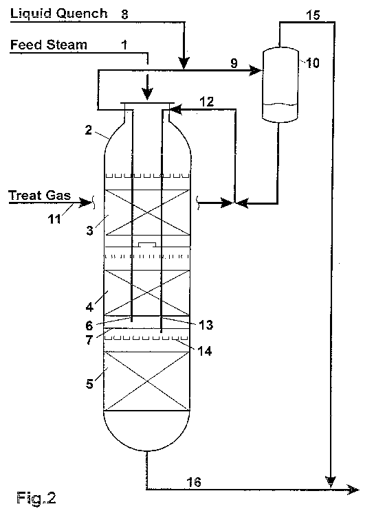
- Fig. 2 shows a hydroprocessing reactor being retrofitted in accordance with a specific embodiment of the invention.
- feed stream 1 containing heavy hydrocarbon feed and hydrogen rich gas is introduced to hydroprocessing reactor 2 containing three catalyst beds.
- Two upper beds 3 and 4 are loaded with catalyst active in hydrogenation of organic sulphur and nitrogen compounds and aromatic compounds and in hydrocracking.
- Lower bed 5 is loaded with catalyst active in hydrocracking.
- Effluent from the second catalyst bed is withdrawn through riser 6, extending from top of reactor and to above partition plate 7 below second catalyst bed.
- process stream 9 enters separator 10.
- the liquid separator effluent is admixed with fresh hydrogen rich treat gas 11.
- This process stream 12 enters hydroprocessing reactor 2 and is passed via downcomer 13 to below partition plate 7, but above distribution plate 14 above the third catalyst bed.
- H 2 S and NH 3 and light hydrocarbons being formed by hydrogenation of the feed in catalyst bed 3 and 4 are removed with gaseous separator effluent 15.
- the admixed liquid process stream 12 enters catalyst bed 5, where liquid hydrocarbon is hydrocracked.
- Reactor effluent 16 is admixed with gaseous separator effluent 15 for further processing.
- Fig. 3 shows a typical hydrotreater which is revamped in accordance with the process of the invention and where the interbed separation takes place inside the reactor.
- Feed stream 1 containing admixed heavy hydrocarbon feed and hydrogen rich gas is introduced to the hydrotreater 2 containing three catalyst beds, the two upper beds 3 and 4 are loaded with catalyst active in hydrogenation of organic sulphur and nitrogen compounds and aromatic compounds and in some hydrocracking, the lower bed 5 is loaded with catalyst active in hydrocracking.
- the effluent from second catalyst bed is separated above tray 7 by means of separation/mixing device 8.
- the liquid phase flows under device 8, while the gas phase is withdrawn by riser 6, extending from top of reactor and down to above the tray 7.
- the fresh hydrogen rich treat gas 11 enters the hydrotreater 2 at the top and is led down by downcomer 13 to the separating/mixing device 8, where it is admixed with the liquid phase.
- the catalyst poisons H 2 S and NH 3 and the light hydrocarbons are removed by the gaseous effluent 15 and clean process stream enters the third catalyst bed 5, where liquid hydrocarbon is hydrocracked.
- the reactor effluent 16 is admixed with the gaseous effluent 15 for further processing.
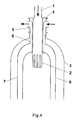
- Fig. 4 shows the essential parts of inlet/outlet arrangement at top of reactor.
- the reactor inlet stream enters the reactor through original inlet 1 and flows through inlet distributor 2, which is extended or replaced.
- inlet distributor 2 which is extended or replaced.
- a spool piece 5 is installed containing the connecting duct 6 to riser 7 and downcomer 8.
- Fig. 5 shows flanges 1 on the original reactor and the flanged spool piece 2 to be installed between flanges 1.
- nozzles 3 connecting reactor and separator are placed on the spool piece.
- Duct 4 connecting inlet/outlet and riser/downcomer is formed by plate 5 being welded to the inside of the spool piece and plate 6 being welded to plate 5.
- Fig. 7 illustrates how the bend of a riser/downcomer 1 and the duct 2 are connected to each other.
- FIG. 8 A horizontal cut, AB, of Fig. 7 is shown on Fig. 8.
- the Table discloses approximate prices of the products and hydrogen, the amount of product obtained with a conventional process and with interbed recycle expressed as percentage of weight of feed flow and prices of the obtained products and consumed hydrogen for the conventional process and for the process of the invention. From the Table it appears that the value of the product is increased by 3.5% and the hydrogen consumption is decreased by 15%. Plant Capacity 4762.5 m 3 /day Specific Gravity 0,9272 Feed Flow 184 ton/hr On-stream Factor 0,95 Operating Days/Year 347
Landscapes
- Chemical & Material Sciences (AREA)
- Oil, Petroleum & Natural Gas (AREA)
- Engineering & Computer Science (AREA)
- Chemical Kinetics & Catalysis (AREA)
- General Chemical & Material Sciences (AREA)
- Organic Chemistry (AREA)
- Production Of Liquid Hydrocarbon Mixture For Refining Petroleum (AREA)
- Cyclones (AREA)
- Organic Low-Molecular-Weight Compounds And Preparation Thereof (AREA)
- Treating Waste Gases (AREA)
- Water Treatment By Electricity Or Magnetism (AREA)
Abstract
- installing a flanged spool piece between an existing man hole flange at top of the reactor;
- retrofitting existing mixer plates to partition plates;
- installing risers extending from top of the reactor to upper surface of the partition plate between two catalyst beds and installing downcomers extending from top of the reactor to lower surface of the partition plate; and
- providing ducts connecting nozzles on the spool piece with the risers and the downcomers.
Description
- The present invention relates to an improved process for hydroprocessing of hydrocarbon feedstock. The process involves interbed separation of gas/liquid phases of a process stream for removal of hydrogenated impurities and gaseous hydrocarbons.
- The invention relates further to a method of retrofitting or modernising an existing hydroprocessing reactor for use in the improved process.
- Hydrocarbon feed stocks and in particular heavy hydrocarbons usually contain organic sulphur and nitrogen compounds that in a subsequent process are undesired impurities because they affect catalyst activity. These impurities must therefor be hydrogenated to hydrogen sulphide and ammonia prior to being treated in a subsequent process for further hydroprocessing of the feed stock.
- A number of known processes for treatment of heavy hydrocarbon raw material fulfil different requirements concerning feed, product and cost of investment.
- Thus, Verachtert et al. (US Patent No. 5,914,029) disclose a process containing a hydroprocessing reactor, cooling in several heat exchangers, gas/liquid separation and stripping of the liquid hydrocarbon.
- Cash (US Patent No. 6,096,190) mentions a simple process for hydrotreatment of two different feedstocks with a common hydrogen source in one reactor. After cooling and separation, the liquid separator effluent is fed to a distillation tower.
- Similarly, Kyan et al. (US Patent No. 5,603,824) send heavy distillate and light distillate to a common reactor for hydrocracking and subsequent dewaxing.
- However, none of the above processes include interbed phase separation and H2S/NH3 removal and interbed product recovery by gas phase separation.
- Both Chervenak et al. (US Patent No. 4,221,653) and Devenathan et al. (US Patent No. 5,624,642) disclose hydrocarbon processing including gas/liquid separation inside reactor, however, the catalyst beds involved are fluidised beds requiring recirculation of the liquid phase.
- Bridge et al. US Patent No. 4,615,789 disclose a hydroprocessing reactor containing three fixed catalyst beds, downward gas/liquid flow and gas/liquid separation before the last bed. This process ensures that the liquid phase bypasses the last catalyst bed and that the gas phase process stream undergoes further hydroprocessing in absence of the liquid hydrocarbons.
- In WO 97/18278 Bixel et al. describe a process for hydrocracking and dewaxing of an oil feed stock to produce lube oil. The process includes two multi-stage towers, where the process stream is cooled by quenching with hydrogen between the catalyst beds, and after first tower the gas phase of the process stream is recycled to the inlet of this first tower.
- Wolk et al. disclose in US patent No. 4,111,663 reactors with up-flow of a slurry of coal, oil and gas, where cooling between beds is performed by addition of cold hydrogen or by withdrawing process gas stream, cooling, separating, removing the liquid and returning the gas phase to the reactor between the beds.
- In patent No. EP 990,693 Kalnes et al. disclose a process for producing light hydrocarbons by integrated hydrotreating and hydrocracking. In this process, the liquid phase of the effluent and the hydrogen rich gas, after further processing, are returned to the hydrocracker.
- In publication DE 2,133,565 Jung et al. describe a process for hydrocracking of hydrocarbon oil, where effluent from first cracker is further processed by distillation and the heaviest fraction is further cracked before being returned to the distillation. The two hydrocracker towers are cooled by hydrogen addition between the beds.
- A process for production of coke by McConaghy et al. is disclosed in SE Patent No. 8,006,852, where hydrocarbon feed is cracked in a cracker furnace before being fractionated and some of the heavier hydrocarbons from the fractionator is further hydrogenated before returning to the cracker furnace and fractionator.
- In US patent No. 3,816,296 Hass et al. describe their process for producing gasoline and midbarrel fuels from higher boiling hydrocarbons. The feed is processed by hydro-refining, cracking, separation with return of the gas phase to hydro-refining inlet and by refractionation of the liquid phase. The heaviest phase from the refractionator is treated in a second cracker, to which also nitrogen compounds are added, in order to control selectivity of the cracking process. The effluent of this second cracker is separated and the gas phase is returned to inlet of second cracker.
- Many of the processes of prior art concerning hydroprocessing involve phase separation of a process stream, and the gas phase is returned to the process or recycled to the inlet of the apparatus, which the process stream just has passed through.
- Prior art fails to teach separation of gas phase from liquid phase between catalyst beds inside a reactor and returning only the liquid phase with the purposes of removing H2S and NH3 and the light hydrocarbons in order to avoid excessive cracking of the light hydrocarbons and to avoid sending poisons to the subsequent catalyst beds.
- In one aspect, this invention provides an improved process for hydroprocessing of a hydrocarbon feedstock, where the hydrocarbon feed stock is hydrotreated by contact with a hydrotreating catalyst and hydrocracked in presence of a subsequent hydrocracking catalyst arranged in one or more reactors. Between the hydrotreating step and the hydrocracking step the two-phase process stream is withdrawn between hydrotreating and hydrocracking catalyst for phase separation into a gaseous and liquid phase. The liquid phase is then cycled to the hydrocracking step after fresh hydrogen rich gas has been added to the liquid phase. Phase separation may be repeated after one or more catalyst beds. Upstream beds are thereby loaded with catalyst active in hydrogenation of organic sulphur, nitrogen, aromatic compounds and optionally in hydrocracking of heavy hydrocarbons if contained in the feed stock. Downstream beds contain a catalyst being active in hydrogenation and/or hydrocracking.
- In the inventive process a gas phase containing H2S and NH3 being formed during hydrotreating of the feed stock and being impurities in the hydrocracking step is removed together with gaseous hydrocarbons preventing further, unintended cracking of these hydrocarbons in this step.
- In further an aspect, this invention provides a method for retrofitting an existing hydroprocessing reactor to be usable in the above hydroprocessing process. Thereby, an existing hydroprocessing reactor is rebuilt without any change in the reactor shell, and with solely minor changes of reactor internals. The inventive method includes that a cylindrical piece connected to the inside piping is inserted between the top flanges of a typical hydroprocessing reactor, the inlet distributor is prolonged or renewed and risers and downcomers are installed.
- Heavy hydrocarbon feedstock typically contains organic sulphur, nitrogen and aromatic compounds, which are undesirable in a downstream hydrocracking process and product. When operating the invention in practice, feed oil is admixed with a hydrogen containing gas and heated to reaction temperatures of 250-450°C before entering a hydroprocessing reactor.
- By contact with a hydrotreating catalyst these compounds are converted to H2S, NH3 and saturated hydrocarbons. H2S and NH3 are impurities that affect catalyst activity and are removed from hydrotreated effluent by phase separation into a liquid and gaseous process stream and withdrawal of the gaseous stream containing light hydrocarbons and the impurities before further hydroprocessing. The liquid stream is admixed with fresh treat gas before entering the hydrocracking step.
- In the hydrocracking step or when hydrocracking a liquid hydrocarbon feed not cotaining sulphur or nitrogen compounds the liquid stream is contacted with hydrocracking catalyst being arranged in one or more catalyst beds. When carrying out the process in a number of reactors and/or catalyst beds, a two-phase process stream is withdrawn from between the catalyst beds and/or reactors and the gas phase is removed as described above. Fresh gas rich in hydrogen is added to the liquid process stream before being introduced in a subsequent catalyst bed. Undesired further cracking of hydrocarbons in the gas phase is thereby substantially avoided. Only small amounts of impurities are introduced to downstream catalyst beds, where the liquid process stream is hydrocracked to lower hydrocarbons in a more efficient way and/or at higher space velocity. Lifetime of the catalyst is considerably prolonged.
- The interbed phase separation can take place both inside and outside the reactor.
- In last case, optionally a catalyst bed can be installed in top of the separator in the gas phase in order to hydrogenate remaining aromatic compounds in the light product.
- Depending of the desired product, ammonia can be added to the liquid phase from interbed separation. This will inhibit cracking reaction in the subsequent catalyst bed and allow operation at higher temperature but with unchanged conversion, thereby heavier hydrocarbons than at lower temperatures will leave the reactor with the gas phase between the catalyst beds, and avoid further cracking, which improves the yield of product.
- Effluent from the final hydrocracking step is admixed with the gaseous effluents obtained in the above separation steps. The thus formed process stream is cooled and liquid heavy hydrocarbons are separated from the stream, while the remaining gas phase is admixed with water, further cooled and fed to a separation unit. The washed process stream is separated in a sour water phase, a liquid light hydrocarbon phase and a hydrogen rich gas being essentially free of N and S compounds. The hydrogen rich stream together with an amount of make-up hydrogen forms the fresh treat gas stream being admixed to the liquid process streams between the above hydroprocessing steps.
- The invention further provides a method for retrofitting existing hydroprocessing reactors for use in a process of this invention. By the method internals of an existing hydroprocessing reactor including optionally additional catalyst beds, risers and downcomers are retrofitted or installed without modifying the expensive reactor shell. In more detail the method comprises
installing a flanged spool piece between an existing man hole flange at top of the reactor;
retrofitting existing mixer plates to partition plates;
installing risers extending from top of the reactor to upper surface of the partition plate between two catalyst beds and installing downcomers extending from top of the reactor to lower surface of the partition plate; and
providing ducts connecting nozzles on the spool piece with the risers and the downcomers. - In the retrofitted reactor catalyst effluent is withdrawn through an installed riser from the reactor and passed to a separator for treating the effluent as described above. The liquid phase obtained in the separator is admixed with fresh treat gas and returned through installed downcomers to a subsequent catalyst bed.
- A retrofit of existing trays to dense pattern flexible trays (US Patent No. 5,688,445) or trays provided with vapour lift tubes (US Patent No. 5,942,162) further increase the yield and conversion in process.
- In case of internal phase separation, the tray below a catalyst bed is designed to let the liquid phase be collected and transferred through a hole in the middle of the tray to next catalyst bed, while the gas phase is removed through the riser. Above and around the middle of the tray a separating/mixing device, open at the bottom, is installed to which the downcomer with fresh hydrogen rich gas is connected.
- By the retrofitting method of the invention, it possible to withdraw and recycle process streams between the catalyst beds without modification of the reactor shell. The inlet pipe of an existing hydroprocessing reactor is typically connected to the cover of 30" manhole at top of reactor. When retrofitting such a conventional hydroprocessing reactor, a cylindrical piece is installed between the flanges of the manhole. The cylindrical piece contains the connections between risers/downcomers inside the hydroprocessing reactor and the piping between the hydroprocessing reactor and a separator.
- By the process of the invention, far better use of the catalyst is obtained as well as prolonged catalyst lifetime. Consequently, the requirement to catalyst volume is reduced, which makes space for the retrofit between catalyst beds and still obtaining a higher yield of product.
-
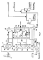
- Fig. 1 is a simplified diagram of a process according to a specific embodiment of the invention for hydroprocessing of heavy hydrocarbon feed with phase separation between catalyst beds.
- Fig. 2 shows a retrofitted hydroprocessing reactor with external phase separation and addition of fresh treat gas upstream a lower catalyst bed.
- Fig. 3 shows a retrofitted hydroprocessing reactor with internal phase separation and addition of fresh treat gas.
- Fig. 4 shows the inlet/outlet system for interbed process streams at top of a retrofitted reactor.
- Fig. 5 discloses a new cylindrical piece to be installed at top and with the ducts connecting the riser/downcomer in a retrofitted reactor.
- Fig. 6 shows a horizontal cross section of the inlet/outlet nozzle and duct of Fig. 5.
- Fig. 7 shows the connection between the vertical oulet/inlet duct and riser/downcomer.
- Fig. 8 is a horizontal cross section of the connection shown on Fig. 7.
-
- Referring to the drawings, a specific embodiment of the invention is illustrated by the simplified flow diagram of Fig. 1. Feed oil is introduced to the process through
line 1 and pumped bypump 2. After admixing of recycle oil inline 3 and then hydrogen rich gas inline 4, the feed mixture is heated in feed/effluent heat exchanger 5 and firedheater 6 before enteringhydrogenator 7.Hydrogenator 7 contains twocatalyst beds 8 with catalyst being active in hydrogenation of organic compounds including sulphur, nitrogen and aromatic compounds contained in the feed mixture and in hydrocracking of hydrocarbons. To control the temperature in the hydrogenation catalyst, hydrogen rich gas is added throughline 9 between the catalyst beds. -
Hydrogenator effluent stream 10 enters aseparator 11 from wheregas phase stream 12 containing H2S, NH3 and cracked hydrocarbons is withdrawn. The liquid separator effluent is admixed with fresh hydrogenrich gas stream 13, and mixedprocess gas stream 14 is fed tohydrocracker 15.Hydrocracker 15 is provided withcatalyst 16 being active in hydrocracking and arranged in three beds. Process streams 17 and 18 between the catalyst beds are withdrawn from the reactor and introduced toseparators liquid streams 17a and 18a are recycled to the cracking catalyst after having been admixed with fresh hydrogen rich gas fromlines 23 and 24. Thereby cracking of gaseous hydrocarbons is avoided and high conversion in all catalyst beds obtained. If required controlled and small amounts of ammonia are introduced throughline 40 intoliquid streams hydrocracker effluent 41 is admixed with gaseous process streams 12, 21 and 22 fromseparators effluent heat exchanger separator 26 from where the heavy hydrocarbon product is withdrawn. The gaseous separator effluent is admixed with water before further cooling (not shown) and introduction intoseparation unit 27 resulting in a sour water stream, a light hydrocarbon product stream and a fresh hydrogen rich treat gas stream. The hydrogen rich treat gas stream is admixed with make-up hydrogen. The combinedtreat gas stream 28 is heated in feed/effluent heat exchanger 25 and forms the hydrogen rich gas used inhydrogenator 7 and inhydrocracker 15. - Fig. 2 shows a hydroprocessing reactor being retrofitted in accordance with a specific embodiment of the invention.
- When operating the reactor, feed
stream 1 containing heavy hydrocarbon feed and hydrogen rich gas is introduced tohydroprocessing reactor 2 containing three catalyst beds. Twoupper beds Lower bed 5 is loaded with catalyst active in hydrocracking. Effluent from the second catalyst bed is withdrawn throughriser 6, extending from top of reactor and toabove partition plate 7 below second catalyst bed. After admixing with liquid quenchstream 8process stream 9 entersseparator 10. The liquid separator effluent is admixed with fresh hydrogenrich treat gas 11. Thisprocess stream 12 entershydroprocessing reactor 2 and is passed viadowncomer 13 to belowpartition plate 7, but abovedistribution plate 14 above the third catalyst bed. H2S and NH3 and light hydrocarbons being formed by hydrogenation of the feed incatalyst bed gaseous separator effluent 15. The admixedliquid process stream 12 enterscatalyst bed 5, where liquid hydrocarbon is hydrocracked. -
Reactor effluent 16 is admixed withgaseous separator effluent 15 for further processing. - Fig. 3 shows a typical hydrotreater which is revamped in accordance with the process of the invention and where the interbed separation takes place inside the reactor.
Feed stream 1 containing admixed heavy hydrocarbon feed and hydrogen rich gas is introduced to thehydrotreater 2 containing three catalyst beds, the twoupper beds lower bed 5 is loaded with catalyst active in hydrocracking. The effluent from second catalyst bed is separated abovetray 7 by means of separation/mixing device 8. The liquid phase flows underdevice 8, while the gas phase is withdrawn byriser 6, extending from top of reactor and down to above thetray 7. The fresh hydrogenrich treat gas 11 enters thehydrotreater 2 at the top and is led down bydowncomer 13 to the separating/mixing device 8, where it is admixed with the liquid phase. The catalyst poisons H2S and NH3 and the light hydrocarbons are removed by thegaseous effluent 15 and clean process stream enters thethird catalyst bed 5, where liquid hydrocarbon is hydrocracked. Thereactor effluent 16 is admixed with thegaseous effluent 15 for further processing. - Fig. 4 shows the essential parts of inlet/outlet arrangement at top of reactor. The reactor inlet stream enters the reactor through
original inlet 1 and flows throughinlet distributor 2, which is extended or replaced. Betweenreactor shell 3 and manhole cover 4 aspool piece 5 is installed containing the connectingduct 6 toriser 7 anddowncomer 8. - Fig. 5 shows
flanges 1 on the original reactor and theflanged spool piece 2 to be installed betweenflanges 1. On the spool piece,nozzles 3 connecting reactor and separator are placed.Duct 4 connecting inlet/outlet and riser/downcomer is formed byplate 5 being welded to the inside of the spool piece andplate 6 being welded toplate 5. - The same is shown in a horizontal cut AB on Fig. 6, where
cylindrical spool piece 1,nozzle 2, the outer plate of theduct 3 and the inner plate of theduct 4 are shown. - Fig. 7 illustrates how the bend of a riser/
downcomer 1 and theduct 2 are connected to each other. - A horizontal cut, AB, of Fig. 7 is shown on Fig. 8.
- The Table below summarises yields obtained by processes without and with withdrawing gas phase between catalyst beds (Interbed ProdRec) in a hydroprocessing reactor unit handling 4762.5 m3/day (30,000 barrels per stream day) of a vacuum gas oil having a specific gravity of 0.9272.
- The Table discloses approximate prices of the products and hydrogen, the amount of product obtained with a conventional process and with interbed recycle expressed as percentage of weight of feed flow and prices of the obtained products and consumed hydrogen for the conventional process and for the process of the invention. From the Table it appears that the value of the product is increased by 3.5% and the hydrogen consumption is decreased by 15%.
Plant Capacity 4762.5 m3/day Specific Gravity 0,9272 Feed Flow 184 ton/hr On-stream Factor 0,95 Operating Days/Year 347 
Claims (3)
- Method for retrofitting an existing hydroprocessing reactor for use in a process for hydroprocessing a hydrocarbon feed comprising the steps ofsaid method comprising the steps of in an existing reactor shella) admixing the feed with a hydrogen rich gas and obtaining a first admixed process stream;b) contacting the first admixed process stream with a first catalyst being active in hydrocracking of hydrocarbon compounds and obtaining a first catalyst effluent process stream;c) separating the first catalyst effluent process stream in a gas stream and a liquid phase stream, and withdrawing the gas phase stream;d) admixing the liquid phase stream with a hydrogen rich gas and obtaining a second admixed process stream;e) contacting the second admixed process gas stream with a second catalyst being active in hydrocracking of hydrocarbon compounds and obtaining a second catalyst effluent process stream;f) withdrawing and admixing the second catalyst effluent process stream with the gas phase stream obtained in step c); andg) withdrawing the admixed process stream provided in step f),
installing a flanged spool piece between an existing man hole flange at top of the reactor;
retrofitting existing mixer plates to partition plates;
installing risers extending from top of the reactor to upper surface of the partition plate between two catalyst beds and installing downcomers extending from top of the reactor to lower surface of the partition plate; and
providing ducts connecting nozzles on the spool piece with the risers and the downcomers. - The method of claim 1, wherein the at least one partition plate in the form of a tray with separating/mixing device is installed.
- The method of claim 1 or 2, wherein at least one existing distribution plate installed a top of a catalyst bed is replaced by a distribution plate with vapour lift tubes.
Applications Claiming Priority (3)
| Application Number | Priority Date | Filing Date | Title |
|---|---|---|---|
| DKPA200001691 | 2000-11-11 | ||
| DK200001691 | 2000-11-11 | ||
| EP01993661A EP1348012B1 (en) | 2000-11-11 | 2001-11-08 | Improved hydroprocessing process and method of retrofitting existing hydroprocessing reactors |
Related Parent Applications (1)
| Application Number | Title | Priority Date | Filing Date |
|---|---|---|---|
| EP01993661A Division EP1348012B1 (en) | 2000-11-11 | 2001-11-08 | Improved hydroprocessing process and method of retrofitting existing hydroprocessing reactors |
Publications (2)
| Publication Number | Publication Date |
|---|---|
| EP1482023A1 true EP1482023A1 (en) | 2004-12-01 |
| EP1482023B1 EP1482023B1 (en) | 2008-04-09 |
Family
ID=8159836
Family Applications (2)
| Application Number | Title | Priority Date | Filing Date |
|---|---|---|---|
| EP01993661A Expired - Lifetime EP1348012B1 (en) | 2000-11-11 | 2001-11-08 | Improved hydroprocessing process and method of retrofitting existing hydroprocessing reactors |
| EP04020687A Expired - Lifetime EP1482023B1 (en) | 2000-11-11 | 2001-11-08 | Method of retrofitting existing hydroprocessing reactors |
Family Applications Before (1)
| Application Number | Title | Priority Date | Filing Date |
|---|---|---|---|
| EP01993661A Expired - Lifetime EP1348012B1 (en) | 2000-11-11 | 2001-11-08 | Improved hydroprocessing process and method of retrofitting existing hydroprocessing reactors |
Country Status (13)
| Country | Link |
|---|---|
| US (1) | US7156977B2 (en) |
| EP (2) | EP1348012B1 (en) |
| JP (1) | JP3762747B2 (en) |
| KR (1) | KR100571731B1 (en) |
| CN (1) | CN1293169C (en) |
| AT (2) | ATE391761T1 (en) |
| AU (2) | AU2002226329B2 (en) |
| CA (1) | CA2427174C (en) |
| DE (2) | DE60133590T2 (en) |
| NO (1) | NO332135B1 (en) |
| RU (1) | RU2235757C1 (en) |
| WO (1) | WO2002038704A2 (en) |
| ZA (1) | ZA200303412B (en) |
Families Citing this family (31)
| Publication number | Priority date | Publication date | Assignee | Title |
|---|---|---|---|---|
| US7282138B2 (en) | 2003-11-05 | 2007-10-16 | Exxonmobil Research And Engineering Company | Multistage removal of heteroatoms and wax from distillate fuel |
| US7384539B2 (en) | 2004-07-28 | 2008-06-10 | Conocophillips Company | Optimized preheating of hydrogen/hydrocarbon feed streams |
| KR101156370B1 (en) | 2005-02-17 | 2012-06-13 | 에스케이에너지 주식회사 | Process for producing ultra low sulfur and low aromatic diesel fuel |
| US7354560B2 (en) | 2006-01-31 | 2008-04-08 | Haldor Topsoe A/S | Process for the production of hydrogen |
| US7906013B2 (en) | 2006-12-29 | 2011-03-15 | Uop Llc | Hydrocarbon conversion process |
| JP5396008B2 (en) * | 2007-05-31 | 2014-01-22 | Jx日鉱日石エネルギー株式会社 | Method for producing alkylbenzenes |
| US7794585B2 (en) * | 2007-10-15 | 2010-09-14 | Uop Llc | Hydrocarbon conversion process |
| US7799208B2 (en) * | 2007-10-15 | 2010-09-21 | Uop Llc | Hydrocracking process |
| US8008534B2 (en) * | 2008-06-30 | 2011-08-30 | Uop Llc | Liquid phase hydroprocessing with temperature management |
| US9279087B2 (en) * | 2008-06-30 | 2016-03-08 | Uop Llc | Multi-staged hydroprocessing process and system |
| US8999141B2 (en) * | 2008-06-30 | 2015-04-07 | Uop Llc | Three-phase hydroprocessing without a recycle gas compressor |
| NL1036368C2 (en) * | 2008-12-24 | 2010-06-28 | Newplant B V | DEVICE FOR CLEANING SMOKE GAS. |
| CA2762093A1 (en) * | 2009-04-15 | 2010-10-21 | Marathon Oil Canada Corporation | Nozzle reactor and method of use |
| US8518241B2 (en) * | 2009-06-30 | 2013-08-27 | Uop Llc | Method for multi-staged hydroprocessing |
| US8221706B2 (en) * | 2009-06-30 | 2012-07-17 | Uop Llc | Apparatus for multi-staged hydroprocessing |
| BR112013015291B1 (en) * | 2010-12-21 | 2019-06-04 | Kao Corporation | A contacting apparatus for contacting gas with liquid in a flow rising in a column container (11, 211, 311), and a method |
| RU2460569C1 (en) * | 2011-02-10 | 2012-09-10 | Эдуард Владимирович Юрьев | Method for modification of gas separating unit (versions) and gas separator (versions) |
| WO2013075850A1 (en) * | 2011-11-22 | 2013-05-30 | Turkiye Petrol Rafinerileri A.S | A diesel production method and system |
| ITMI20121465A1 (en) * | 2012-09-03 | 2014-03-04 | Eni Spa | METHOD TO CONVERT A CONVENTIONAL REFINERY OF MINERAL OILS IN A BIOFINERY |
| US20140137801A1 (en) * | 2012-10-26 | 2014-05-22 | Applied Materials, Inc. | Epitaxial chamber with customizable flow injection |
| US9162938B2 (en) * | 2012-12-11 | 2015-10-20 | Chevron Lummus Global, Llc | Conversion of triacylglycerides-containing oils to hydrocarbons |
| CN103965953B (en) | 2013-01-30 | 2015-07-22 | 中国石油天然气股份有限公司 | Distillate oil two-phase hydrogenation reactor and hydrogenation process method |
| US9650312B2 (en) * | 2013-03-14 | 2017-05-16 | Lummus Technology Inc. | Integration of residue hydrocracking and hydrotreating |
| CN104941525A (en) * | 2014-03-27 | 2015-09-30 | 何巨堂 | Down-flow type reactor |
| EP3215589B1 (en) * | 2014-11-06 | 2020-05-06 | BP Europa SE | Process and apparatus for hydroconversion of hydrocarbons |
| CN105754649B (en) * | 2014-12-20 | 2018-06-19 | 中国石油化工股份有限公司 | A kind of method for improving hydrocracking unit safety in operation |
| EP3274425B1 (en) | 2015-03-23 | 2021-06-16 | ExxonMobil Research and Engineering Company | Hydrocracking process for high yields of high quality lube products |
| BR112017026375B1 (en) * | 2015-08-06 | 2021-03-02 | Uop Llc | process to convert oil processing units into a renewable fuel processing plant |
| WO2019023655A1 (en) * | 2017-07-27 | 2019-01-31 | Kellogg Brown & Root Llc | Method for revamping vertical converters having a flanged pressure shell extension for housing an internal heat exchanger |
| US10287515B1 (en) * | 2017-11-30 | 2019-05-14 | Benjamin Cowart | Method for producing an American petroleum institute standards group III base stock from vacuum gas oil |
| US11154793B2 (en) | 2018-03-28 | 2021-10-26 | Uop Llc | Apparatus for gas-liquid contacting |
Citations (1)
| Publication number | Priority date | Publication date | Assignee | Title |
|---|---|---|---|---|
| EP0234123A1 (en) * | 1986-01-03 | 1987-09-02 | Mobil Oil Corporation | Hydrodewaxing method and apparatus |
Family Cites Families (18)
| Publication number | Priority date | Publication date | Assignee | Title |
|---|---|---|---|---|
| US2432745A (en) * | 1944-05-19 | 1947-12-16 | Filtrol Corp | Catalytic conversion of hydrocarbons |
| DE1770267A1 (en) * | 1967-04-25 | 1971-12-23 | Atlantic Richfield Co | Process for the desulphurization of petroleum products |
| US3528908A (en) * | 1967-11-17 | 1970-09-15 | Mobil Oil Corp | Catalytic hydrocracking process employing ascending reaction temperatures |
| US3702818A (en) * | 1968-05-23 | 1972-11-14 | Mobil Oil Corp | Hydrocracking process with zeolite and amorphous base catalysts |
| US3554898A (en) * | 1968-08-29 | 1971-01-12 | Union Oil Co | Recycle hydrocracking process for converting heavy oils to middle distillates |
| GB1191958A (en) | 1968-10-08 | 1970-05-13 | Shell Int Research | Three-Stage Hydrocracking Process |
| US3816296A (en) * | 1972-11-13 | 1974-06-11 | Union Oil Co | Hydrocracking process |
| US3983029A (en) * | 1973-03-02 | 1976-09-28 | Chevron Research Company | Hydrotreating catalyst and process |
| NL7605356A (en) | 1975-05-21 | 1976-11-23 | Inst Francais Du Petrole | PROCESS FOR HYDROKRAKING OF HYDROCARBON OILS. |
| US4435275A (en) | 1982-05-05 | 1984-03-06 | Mobil Oil Corporation | Hydrocracking process for aromatics production |
| JPH01185392A (en) | 1988-01-19 | 1989-07-24 | Nippon Oil Co Ltd | Hydrocracking method of heavy oils |
| GB8819121D0 (en) * | 1988-08-11 | 1988-09-14 | Shell Int Research | Process for hydrocracking of hydrocarbonaceous feedstock |
| DE68901696T2 (en) * | 1988-08-11 | 1992-12-17 | Shell Int Research | METHOD FOR HYDROCRACKING HYDROCARBON INSERTS. |
| US5184386A (en) * | 1988-12-09 | 1993-02-09 | Ammonia Casale S.A. | Method for retrofitting carbon monoxide conversion reactors |
| US5688445A (en) * | 1995-07-31 | 1997-11-18 | Haldor Topsoe A/S | Distributor means and method |
| US5840933A (en) * | 1996-10-29 | 1998-11-24 | Arco Chemical Technology, L.P. | Catalytic converter system and progress |
| ES2251010T5 (en) * | 1996-12-19 | 2011-04-26 | Haldor Topsoe A/S | DEVICE OF DISTRIBUTION OF TWO PHASES OF DOWN CURRENT. |
| US5968346A (en) | 1998-09-16 | 1999-10-19 | Exxon Research And Engineering Co. | Two stage hydroprocessing with vapor-liquid interstage contacting for vapor heteroatom removal |
-
2001
- 2001-11-08 AU AU2002226329A patent/AU2002226329B2/en not_active Ceased
- 2001-11-08 DE DE60133590T patent/DE60133590T2/en not_active Expired - Lifetime
- 2001-11-08 KR KR1020037006384A patent/KR100571731B1/en not_active IP Right Cessation
- 2001-11-08 EP EP01993661A patent/EP1348012B1/en not_active Expired - Lifetime
- 2001-11-08 RU RU2003117367/04A patent/RU2235757C1/en not_active IP Right Cessation
- 2001-11-08 US US10/416,026 patent/US7156977B2/en not_active Expired - Fee Related
- 2001-11-08 DE DE60141606T patent/DE60141606D1/en not_active Expired - Lifetime
- 2001-11-08 EP EP04020687A patent/EP1482023B1/en not_active Expired - Lifetime
- 2001-11-08 CA CA002427174A patent/CA2427174C/en not_active Expired - Fee Related
- 2001-11-08 CN CNB01818670XA patent/CN1293169C/en not_active Expired - Fee Related
- 2001-11-08 WO PCT/EP2001/012949 patent/WO2002038704A2/en active IP Right Grant
- 2001-11-08 JP JP2002542025A patent/JP3762747B2/en not_active Expired - Fee Related
- 2001-11-08 AT AT04020687T patent/ATE391761T1/en not_active IP Right Cessation
- 2001-11-08 AU AU2632902A patent/AU2632902A/en active Pending
- 2001-11-08 AT AT01993661T patent/ATE461263T1/en not_active IP Right Cessation
-
2003
- 2003-05-02 ZA ZA200303412A patent/ZA200303412B/en unknown
- 2003-05-09 NO NO20032087A patent/NO332135B1/en not_active IP Right Cessation
Patent Citations (1)
| Publication number | Priority date | Publication date | Assignee | Title |
|---|---|---|---|---|
| EP0234123A1 (en) * | 1986-01-03 | 1987-09-02 | Mobil Oil Corporation | Hydrodewaxing method and apparatus |
Also Published As
| Publication number | Publication date |
|---|---|
| WO2002038704A3 (en) | 2003-08-07 |
| JP2004514021A (en) | 2004-05-13 |
| WO2002038704A2 (en) | 2002-05-16 |
| EP1348012A2 (en) | 2003-10-01 |
| KR20030062331A (en) | 2003-07-23 |
| ATE461263T1 (en) | 2010-04-15 |
| EP1348012B1 (en) | 2010-03-17 |
| KR100571731B1 (en) | 2006-04-17 |
| WO2002038704B1 (en) | 2003-09-18 |
| ZA200303412B (en) | 2004-08-02 |
| DE60133590T2 (en) | 2009-06-04 |
| NO332135B1 (en) | 2012-07-02 |
| CN1293169C (en) | 2007-01-03 |
| AU2002226329B2 (en) | 2006-02-02 |
| RU2235757C1 (en) | 2004-09-10 |
| DE60133590D1 (en) | 2008-05-21 |
| US7156977B2 (en) | 2007-01-02 |
| NO20032087L (en) | 2003-07-09 |
| JP3762747B2 (en) | 2006-04-05 |
| EP1482023B1 (en) | 2008-04-09 |
| DE60141606D1 (en) | 2010-04-29 |
| CA2427174A1 (en) | 2002-05-16 |
| CA2427174C (en) | 2009-04-07 |
| CN1474866A (en) | 2004-02-11 |
| ATE391761T1 (en) | 2008-04-15 |
| AU2632902A (en) | 2002-05-21 |
| NO20032087D0 (en) | 2003-05-09 |
| US20040045870A1 (en) | 2004-03-11 |
Similar Documents
| Publication | Publication Date | Title |
|---|---|---|
| US7156977B2 (en) | Hydroprocessing process and method of retrofitting existing hydroprocessing reactors | |
| AU2002226329A1 (en) | Improved hydroprocessing process and method of retrofitting existing hydroprocessing reactors | |
| JP5651281B2 (en) | Method and apparatus for conversion of heavy petroleum fraction in ebullated bed with production of middle distillate with very low sulfur content | |
| EP0944692B1 (en) | Hydroprocessing in a countercurrent reaction vessel | |
| CA2330308C (en) | Three stage cocurrent liquid and vapor hydroprocessing | |
| CA2262370C (en) | Countercurrent reaction vessel | |
| CN108219836A (en) | Reduce the method for hydrogen cracking and device of multi-nucleus aromatic compound | |
| WO2002031087A1 (en) | Two stage hydroprocessing and stripping in a single reaction vessel | |
| CN110408427B (en) | Process for hydrocracking a hydrocarbon feedstock | |
| CN104650972B (en) | Reduce the method for hydrogen cracking of light fraction product sulfur content | |
| US6569314B1 (en) | Countercurrent hydroprocessing with trickle bed processing of vapor product stream | |
| JPH1060456A (en) | Hydrogenation treatment of heavy oil and device for hydrogenation treatment | |
| CN104650974B (en) | Reduce the hydrocracking method of light fraction product sulfur content | |
| CN116064126A (en) | Fischer-Tropsch synthesis oil hydrogenation device and method | |
| WO2004099347A1 (en) | Improved countercurrent hydroprocessing method | |
| CN114196438A (en) | Hydrogenation process and hydrogenation system for treating high-nitrogen raw material |
Legal Events
| Date | Code | Title | Description |
|---|---|---|---|
| PUAI | Public reference made under article 153(3) epc to a published international application that has entered the european phase |
Free format text: ORIGINAL CODE: 0009012 |
|
| 17P | Request for examination filed |
Effective date: 20040831 |
|
| AC | Divisional application: reference to earlier application |
Ref document number: 1348012 Country of ref document: EP Kind code of ref document: P |
|
| AK | Designated contracting states |
Kind code of ref document: A1 Designated state(s): AT BE CH CY DE DK ES FI FR GB GR IE IT LI LU MC NL PT SE TR |
|
| AKX | Designation fees paid |
Designated state(s): AT BE CH CY DE DK ES FI FR GB GR IE IT LI LU MC NL PT SE TR |
|
| GRAP | Despatch of communication of intention to grant a patent |
Free format text: ORIGINAL CODE: EPIDOSNIGR1 |
|
| GRAS | Grant fee paid |
Free format text: ORIGINAL CODE: EPIDOSNIGR3 |
|
| GRAA | (expected) grant |
Free format text: ORIGINAL CODE: 0009210 |
|
| AC | Divisional application: reference to earlier application |
Ref document number: 1348012 Country of ref document: EP Kind code of ref document: P |
|
| AK | Designated contracting states |
Kind code of ref document: B1 Designated state(s): AT BE CH CY DE DK ES FI FR GB GR IE IT LI LU MC NL PT SE TR |
|
| REG | Reference to a national code |
Ref country code: GB Ref legal event code: FG4D |
|
| REG | Reference to a national code |
Ref country code: CH Ref legal event code: EP |
|
| REG | Reference to a national code |
Ref country code: IE Ref legal event code: FG4D |
|
| REF | Corresponds to: |
Ref document number: 60133590 Country of ref document: DE Date of ref document: 20080521 Kind code of ref document: P |
|
| NLV1 | Nl: lapsed or annulled due to failure to fulfill the requirements of art. 29p and 29m of the patents act | ||
| PG25 | Lapsed in a contracting state [announced via postgrant information from national office to epo] |
Ref country code: NL Free format text: LAPSE BECAUSE OF FAILURE TO SUBMIT A TRANSLATION OF THE DESCRIPTION OR TO PAY THE FEE WITHIN THE PRESCRIBED TIME-LIMIT Effective date: 20080409 Ref country code: ES Free format text: LAPSE BECAUSE OF FAILURE TO SUBMIT A TRANSLATION OF THE DESCRIPTION OR TO PAY THE FEE WITHIN THE PRESCRIBED TIME-LIMIT Effective date: 20080720 Ref country code: PT Free format text: LAPSE BECAUSE OF FAILURE TO SUBMIT A TRANSLATION OF THE DESCRIPTION OR TO PAY THE FEE WITHIN THE PRESCRIBED TIME-LIMIT Effective date: 20080909 |
|
| EN | Fr: translation not filed | ||
| PG25 | Lapsed in a contracting state [announced via postgrant information from national office to epo] |
Ref country code: DK Free format text: LAPSE BECAUSE OF FAILURE TO SUBMIT A TRANSLATION OF THE DESCRIPTION OR TO PAY THE FEE WITHIN THE PRESCRIBED TIME-LIMIT Effective date: 20080409 Ref country code: SE Free format text: LAPSE BECAUSE OF FAILURE TO SUBMIT A TRANSLATION OF THE DESCRIPTION OR TO PAY THE FEE WITHIN THE PRESCRIBED TIME-LIMIT Effective date: 20080709 |
|
| PLBE | No opposition filed within time limit |
Free format text: ORIGINAL CODE: 0009261 |
|
| STAA | Information on the status of an ep patent application or granted ep patent |
Free format text: STATUS: NO OPPOSITION FILED WITHIN TIME LIMIT |
|
| PG25 | Lapsed in a contracting state [announced via postgrant information from national office to epo] |
Ref country code: BE Free format text: LAPSE BECAUSE OF FAILURE TO SUBMIT A TRANSLATION OF THE DESCRIPTION OR TO PAY THE FEE WITHIN THE PRESCRIBED TIME-LIMIT Effective date: 20080409 |
|
| 26N | No opposition filed |
Effective date: 20090112 |
|
| PG25 | Lapsed in a contracting state [announced via postgrant information from national office to epo] |
Ref country code: FR Free format text: LAPSE BECAUSE OF FAILURE TO SUBMIT A TRANSLATION OF THE DESCRIPTION OR TO PAY THE FEE WITHIN THE PRESCRIBED TIME-LIMIT Effective date: 20090130 |
|
| PG25 | Lapsed in a contracting state [announced via postgrant information from national office to epo] |
Ref country code: MC Free format text: LAPSE BECAUSE OF NON-PAYMENT OF DUE FEES Effective date: 20081130 |
|
| REG | Reference to a national code |
Ref country code: CH Ref legal event code: PL |
|
| PG25 | Lapsed in a contracting state [announced via postgrant information from national office to epo] |
Ref country code: IT Free format text: LAPSE BECAUSE OF FAILURE TO SUBMIT A TRANSLATION OF THE DESCRIPTION OR TO PAY THE FEE WITHIN THE PRESCRIBED TIME-LIMIT Effective date: 20080409 |
|
| PG25 | Lapsed in a contracting state [announced via postgrant information from national office to epo] |
Ref country code: CY Free format text: LAPSE BECAUSE OF FAILURE TO SUBMIT A TRANSLATION OF THE DESCRIPTION OR TO PAY THE FEE WITHIN THE PRESCRIBED TIME-LIMIT Effective date: 20080409 |
|
| PG25 | Lapsed in a contracting state [announced via postgrant information from national office to epo] |
Ref country code: CH Free format text: LAPSE BECAUSE OF NON-PAYMENT OF DUE FEES Effective date: 20081130 Ref country code: LI Free format text: LAPSE BECAUSE OF NON-PAYMENT OF DUE FEES Effective date: 20081130 Ref country code: IE Free format text: LAPSE BECAUSE OF NON-PAYMENT OF DUE FEES Effective date: 20081110 |
|
| PG25 | Lapsed in a contracting state [announced via postgrant information from national office to epo] |
Ref country code: AT Free format text: LAPSE BECAUSE OF NON-PAYMENT OF DUE FEES Effective date: 20081108 |
|
| PG25 | Lapsed in a contracting state [announced via postgrant information from national office to epo] |
Ref country code: FI Free format text: LAPSE BECAUSE OF FAILURE TO SUBMIT A TRANSLATION OF THE DESCRIPTION OR TO PAY THE FEE WITHIN THE PRESCRIBED TIME-LIMIT Effective date: 20080409 |
|
| PG25 | Lapsed in a contracting state [announced via postgrant information from national office to epo] |
Ref country code: LU Free format text: LAPSE BECAUSE OF NON-PAYMENT OF DUE FEES Effective date: 20081108 |
|
| PG25 | Lapsed in a contracting state [announced via postgrant information from national office to epo] |
Ref country code: TR Free format text: LAPSE BECAUSE OF FAILURE TO SUBMIT A TRANSLATION OF THE DESCRIPTION OR TO PAY THE FEE WITHIN THE PRESCRIBED TIME-LIMIT Effective date: 20080409 |
|
| PG25 | Lapsed in a contracting state [announced via postgrant information from national office to epo] |
Ref country code: GR Free format text: LAPSE BECAUSE OF FAILURE TO SUBMIT A TRANSLATION OF THE DESCRIPTION OR TO PAY THE FEE WITHIN THE PRESCRIBED TIME-LIMIT Effective date: 20080710 |
|
| PGFP | Annual fee paid to national office [announced via postgrant information from national office to epo] |
Ref country code: GB Payment date: 20131127 Year of fee payment: 13 Ref country code: DE Payment date: 20131127 Year of fee payment: 13 |
|
| REG | Reference to a national code |
Ref country code: DE Ref legal event code: R119 Ref document number: 60133590 Country of ref document: DE |
|
| GBPC | Gb: european patent ceased through non-payment of renewal fee |
Effective date: 20141108 |
|
| PG25 | Lapsed in a contracting state [announced via postgrant information from national office to epo] |
Ref country code: GB Free format text: LAPSE BECAUSE OF NON-PAYMENT OF DUE FEES Effective date: 20141108 Ref country code: DE Free format text: LAPSE BECAUSE OF NON-PAYMENT OF DUE FEES Effective date: 20150602 |