EP1481902B1 - Single pin gripper assembly for strapping machine head - Google Patents
Single pin gripper assembly for strapping machine head Download PDFInfo
- Publication number
- EP1481902B1 EP1481902B1 EP04010251A EP04010251A EP1481902B1 EP 1481902 B1 EP1481902 B1 EP 1481902B1 EP 04010251 A EP04010251 A EP 04010251A EP 04010251 A EP04010251 A EP 04010251A EP 1481902 B1 EP1481902 B1 EP 1481902B1
- Authority
- EP
- European Patent Office
- Prior art keywords
- roller
- strapping
- openings
- follower block
- spring stack
- Prior art date
- Legal status (The legal status is an assumption and is not a legal conclusion. Google has not performed a legal analysis and makes no representation as to the accuracy of the status listed.)
- Expired - Lifetime
Links
- 238000007789 sealing Methods 0.000 claims description 10
- 230000000712 assembly Effects 0.000 claims description 6
- 238000000429 assembly Methods 0.000 claims description 6
- 238000012986 modification Methods 0.000 description 2
- 230000004048 modification Effects 0.000 description 2
- 230000006835 compression Effects 0.000 description 1
- 238000007906 compression Methods 0.000 description 1
- 230000000694 effects Effects 0.000 description 1
- 238000010438 heat treatment Methods 0.000 description 1
- 238000003825 pressing Methods 0.000 description 1
- 238000003466 welding Methods 0.000 description 1
Images

Classifications
-
- B—PERFORMING OPERATIONS; TRANSPORTING
- B65—CONVEYING; PACKING; STORING; HANDLING THIN OR FILAMENTARY MATERIAL
- B65B—MACHINES, APPARATUS OR DEVICES FOR, OR METHODS OF, PACKAGING ARTICLES OR MATERIALS; UNPACKING
- B65B13/00—Bundling articles
- B65B13/18—Details of, or auxiliary devices used in, bundling machines or bundling tools
- B65B13/24—Securing ends of binding material
- B65B13/32—Securing ends of binding material by welding, soldering, or heat-sealing; by applying adhesive
Definitions
- the present invention is directed to an improved gripper assembly for a strapping machine strapping head. More particularly, the present invention is directed to a gripper assembly for use in a strapping machine head that uses a single pin and a single spring stack for effecting proper strap grip for strap tensioning and welding.
- Strapping machines are in widespread use for securing straps around loads.
- One type of known strapper includes a strapping head and drive mechanism mounted within a frame.
- a chute is mounted to the frame, through which the strapping material is fed.
- the chute is mounted at about a work surface, and the strapping head is mounted to a horizontal or vertical portion (or perhaps an inclined portion) of the chute.
- the strapping or sealing head provides a number of functions.
- the strapping head includes a plurality of grippers for gripping the strap during the course of a strapping operation.
- the strapping head also includes a cutter to cut the strap from a strap source or supply.
- the strapping head includes a sealer to seal an overlying course of strapping material onto itself. This seal is commonly referred to as a weld and is effected by heating overlying courses of the strap by use of a vibrating element.
- a first course of strapping material (e.g., the leading end of the strapping material) is conveyed from a dispenser into a feed arrangement and into the strapping head.
- the leading end is conveyed through the strapping head (in proximity to a first or loop gripper), through the chute, and back to the strapping head.
- the leading end is conveyed in the strapping head over a second or end gripper to a position within the sealing region.
- the leading end is then gripped by the end gripper and the strapping material is tensioned around the load. Subsequent to tensioning, the trailing end of the strapping material is gripped by the loop gripper and the seal or weld is effected in the strap. The strap is then cut from the source or supply and is released from the strapping machine.
- known strapping machines use a cam that contacts a gripper assembly to effect this grip of the strap.
- Known gripper assemblies include a roller (for contact with the machine camming surface) mounted to a cam follower block by a pin.
- a grip is rigidly mounted to a grip support which is in turn mounted to the cam follower by a second pin.
- a pair of side-by-side spring sets are positioned between the cam follower and the grip support to permit the grip to apply a balanced pressure to strap.
- two pins are needed (one for mounting the roller to the cam follower block and a second for mounting the grip support to the cam follower block.
- side-by-side sets of springs are needed to provide proper application and alignment when applying pressure to the strap (e.g., during spring compression).
- a gripper assembly for a strapping machine strapping head that reduces the overall size and weight of the gripper.
- such a gripper uses a reduced number of components thus resulting in a simpler, less complex gripper configuration while maintaining gripper components aligned during gripping operation.
- gripper assembly for strapping head as defined in claim 1 includes a body having a generally rectangular cross-section and defining a cavity therein having an end wall.
- the body has a gripping pad on an exterior portion thereof and includes openings on opposing walls thereof. In a preferred embodiment, the openings are slightly elongated or notched.
- a single spring stack is disposed in the cavity. An end of the spring stack abuts the inner end wall of the body.
- a follower block is positioned in the cavity.
- the follower block has a base and a roller support portion.
- the roller support portion has openings therein that align with the body openings.
- a roller is positioned in the roller support portion.
- the roller has a passage therethrough that aligns with the body and follower block openings.
- a retaining element preferably a retaining pin, is disposed through the body openings, the follower block openings and the roller passage.
- the retaining pin is disposed to maintain the follower block within the body with the roller secured thereto and to maintain the spring stack captured within the body cavity.
- the elongated body openings permit slight longitudinal movement of the roller and follower block relative to the body to compress and expand the spring stack.
- a present gripper assembly includes two concentrically disposed springs and a single retaining pin.
- a strapping head having the present single pin gripper assembly as defined in claim 8 is also disclosed.
- the present gripper assembly reduces the overall size and weight of the gripper.
- Such a gripper uses a reduced number of components and results in a simpler, less complex gripper configuration while maintaining gripper components aligned during gripping operation.
- FIG. 1 is a perspective view of an exemplary strapping machine having a strapping head with single pin gripper assemblies embodying the principles of the present invention
- FIG. 2 is a schematic illustration of the strapping head showing the strap path through the head and the relative location of the gripper assemblies and the strap as positioned at the grips;
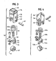
- FIG. 3 is a top perspective exploded view of the gripper assembly
- FIG. 4 is a bottom perspective exploded view of the gripper assembly.
- FIG. 1 there is shown a strapping machine 10 having a strapping head 12 having single pin gripper assemblies 14 (see FIG. 2) embodying the principles of the present invention.
- the strapping machine 10 includes, generally, a frame 16, a strap chute 18, a feed assembly 20 and the strapping or sealing head 12.
- a controller 22 provides automatic operation and control of the strapper 10.
- FIG. 2 there is shown schematically the position of the first S 1 and second S 2 courses of strapping material as they are positioned within the strapping head 12 during the strapping operation.
- a leading end L of the strap is positioned at an end gripping assembly 14a (or end grip) and a trailing end T of the strap is positioned at a loop gripping assembly 14b (or loop grip).
- Both of the grips 14a,b are positioned within the sealing head 12 for reciprocating movement, and are shown in the open or non-gripping position.
- the end grip 14a Upon a predetermined signal, the end grip 14a will actuate to secure the strap between the grip 14a and the sealing head body 24, and the strap will then be tensioned.
- the loop grip 14b will then actuate to secure the strap to the sealing head body 24 so that the strap is secured at both sides of the sealer 26 and the sealer (vibrating welder) is actuated.
- each gripper assembly 14a,b includes a gripper body 30 having a grip pad 32 at the end 34 thereof.
- the body 30 has a cavity 36 therein and an end wall 38 at the base of the cavity 36. In that the body 30 is oriented with the cavity 36 downward, the end wall 38 is positioned at the top of the (inverted) cavity 36.
- the body 30 further includes a pair of pin openings 40 in opposing walls.
- the openings 40 are formed having a slightly elongated shape extending in a longitudinal direction, as indicated by the arrow at 42, along the body 30.
- a cam roller 44 is mounted to a cam follower block 46.
- the roller 44 includes a central passage 48 for receiving a shaft, as will be described below.
- the roller 44 is configured for engagement with a cam lobe or surface (not shown) to urge the roller 44 and follower block 46 toward or into the cavity 36.
- the follower block 46 has a piston-like shape and is configured for mounting within the gripper body 30.
- the follower block 46 has a generally flat base 50 and a depending roller support portion 52 that is essentially formed as a pair of legs that depend from the base 50.
- the legs 52a,b each include a pin opening 54 therein.
- the follower block 46 includes a projection 56 extending outwardly therefrom that traverses within a channel 58 formed in the wall of the body 30.
- a single stack (or set) of springs 60 is positioned in the body 30, on the follower block base 50. In this manner, the springs 60 are captured between the follower block 46 and the inner wall of the body (within the cavity 36).
- a single set of two concentric springs 60a,b is used to bias the gripper body 30 (relative to the roller 44 and follower block 46).
- the assembly 14 is secured by a single retaining element 62.
- the retaining element is a pin 62.
- the pin 62 is positioned through the body pin openings 40, through the follower block pin openings 54 and through the roller passage 48.
- the pin 62 serves as the rotational axis for the roller 44, as well as to maintain the gripper 14 as an assembly.
- the present gripper 14, which includes a single spring set 60a,b and a single pin 62 is significantly smaller and lighter than known grippers and is mechanically a less complex assembly (due a lesser number of parts).
- the body openings 40 (for receiving the pin 62) are elongated or notched (in the direction indicated at 42). This permits a small amount of reciprocating movement of the follower block 46 and roller 44 within and relative to the body 30. This assures that an appropriate force is exerted by the grip pad 32 on the strap, and further assures good contact and holding of and by the grip pad 32 on the strap, even when taking in to consideration the tolerances for strap thickness.
Description
- The present invention is directed to an improved gripper assembly for a strapping machine strapping head. More particularly, the present invention is directed to a gripper assembly for use in a strapping machine head that uses a single pin and a single spring stack for effecting proper strap grip for strap tensioning and welding.
- Strapping machines are in widespread use for securing straps around loads. One type of known strapper includes a strapping head and drive mechanism mounted within a frame. A chute is mounted to the frame, through which the strapping material is fed.
- In a typical stationary strapper, the chute is mounted at about a work surface, and the strapping head is mounted to a horizontal or vertical portion (or perhaps an inclined portion) of the chute. The strapping or sealing head provides a number of functions. First, the strapping head includes a plurality of grippers for gripping the strap during the course of a strapping operation. The strapping head also includes a cutter to cut the strap from a strap source or supply. Last, the strapping head includes a sealer to seal an overlying course of strapping material onto itself. This seal is commonly referred to as a weld and is effected by heating overlying courses of the strap by use of a vibrating element.
- In the course of the strapping operation, a first course of strapping material (e.g., the leading end of the strapping material) is conveyed from a dispenser into a feed arrangement and into the strapping head. The leading end is conveyed through the strapping head (in proximity to a first or loop gripper), through the chute, and back to the strapping head. The leading end is conveyed in the strapping head over a second or end gripper to a position within the sealing region.
- The leading end is then gripped by the end gripper and the strapping material is tensioned around the load. Subsequent to tensioning, the trailing end of the strapping material is gripped by the loop gripper and the seal or weld is effected in the strap. The strap is then cut from the source or supply and is released from the strapping machine.
- It is important that the grippers maintain a firm and sure grip on the strap at all "gripping" times. To this end, known strapping machines use a cam that contacts a gripper assembly to effect this grip of the strap. Known gripper assemblies include a roller (for contact with the machine camming surface) mounted to a cam follower block by a pin. A grip is rigidly mounted to a grip support which is in turn mounted to the cam follower by a second pin. A pair of side-by-side spring sets are positioned between the cam follower and the grip support to permit the grip to apply a balanced pressure to strap.
- In such an arrangement, two pins are needed (one for mounting the roller to the cam follower block and a second for mounting the grip support to the cam follower block. Moreover, side-by-side sets of springs are needed to provide proper application and alignment when applying pressure to the strap (e.g., during spring compression).
- While such an arrangement functions well, it does have its drawbacks. One such drawback is the complexity of the design. The need for multiple pins and multiple spring sets requires additional moving parts and components which, in mechanical systems generally is undesirable. In addition, the need for multiple pins and side-by-sides spring sets increases the overall size and thus the weight of the gripper.
A gripper assembly and a strapping head in accordance with the preambles ofclaims 1 and 8 are known from EP-A-1 170 214. - Accordingly, there exists a need for a gripper assembly for a strapping machine strapping head that reduces the overall size and weight of the gripper. Desirably, such a gripper uses a reduced number of components thus resulting in a simpler, less complex gripper configuration while maintaining gripper components aligned during gripping operation.
- gripper assembly for strapping head as defined in
claim 1 includes a body having a generally rectangular cross-section and defining a cavity therein having an end wall. The body has a gripping pad on an exterior portion thereof and includes openings on opposing walls thereof. In a preferred embodiment, the openings are slightly elongated or notched. - A single spring stack is disposed in the cavity. An end of the spring stack abuts the inner end wall of the body. A follower block is positioned in the cavity. The follower block has a base and a roller support portion. The roller support portion has openings therein that align with the body openings. A roller is positioned in the roller support portion. The roller has a passage therethrough that aligns with the body and follower block openings.
- A retaining element, preferably a retaining pin, is disposed through the body openings, the follower block openings and the roller passage. The retaining pin is disposed to maintain the follower block within the body with the roller secured thereto and to maintain the spring stack captured within the body cavity.
- The elongated body openings permit slight longitudinal movement of the roller and follower block relative to the body to compress and expand the spring stack.
- A present gripper assembly includes two concentrically disposed springs and a single retaining pin. A strapping head having the present single pin gripper assembly as defined in claim 8 is also disclosed.
- Advantageously, the present gripper assembly reduces the overall size and weight of the gripper. Such a gripper uses a reduced number of components and results in a simpler, less complex gripper configuration while maintaining gripper components aligned during gripping operation.
- These and other features and advantages of the present invention will be apparent from the following detailed description, in conjunction with the appended claims.
- The benefits and advantages of the present invention will become more readily apparent to those of ordinary skill in the relevant art after reviewing the following detailed description and accompanying drawings, wherein:
- FIG. 1 is a perspective view of an exemplary strapping machine having a strapping head with single pin gripper assemblies embodying the principles of the present invention;
- FIG. 2 is a schematic illustration of the strapping head showing the strap path through the head and the relative location of the gripper assemblies and the strap as positioned at the grips;
- FIG. 3 is a top perspective exploded view of the gripper assembly; and
- FIG. 4 is a bottom perspective exploded view of the gripper assembly.
- While the present invention is susceptible of embodiment in various forms, there is shown in the drawings and will hereinafter be described a presently preferred embodiment with the understanding that the present disclosure is to be considered an exemplification of the invention and is not intended to limit the invention to the specific embodiment illustrated.
- It should be further understood that the title of this section of this specification, namely, "Detailed Description Of The Invention", relates to a requirement of the United States Patent Office, and does not imply, nor should be inferred to limit the subject matter disclosed herein.
- Referring to the figures and in particular FIG. 1, there is shown a strapping
machine 10 having a strappinghead 12 having single pin gripper assemblies 14 (see FIG. 2) embodying the principles of the present invention. The strappingmachine 10 includes, generally, aframe 16, astrap chute 18, afeed assembly 20 and the strapping or sealinghead 12. Acontroller 22 provides automatic operation and control of thestrapper 10. - Referring now to FIG. 2, there is shown schematically the position of the first S1 and second S2 courses of strapping material as they are positioned within the strapping
head 12 during the strapping operation. As illustrated, a leading end L of the strap is positioned at anend gripping assembly 14a (or end grip) and a trailing end T of the strap is positioned at aloop gripping assembly 14b (or loop grip). Both of thegrips 14a,b are positioned within the sealinghead 12 for reciprocating movement, and are shown in the open or non-gripping position. Upon a predetermined signal, theend grip 14a will actuate to secure the strap between thegrip 14a and the sealinghead body 24, and the strap will then be tensioned. Theloop grip 14b will then actuate to secure the strap to the sealinghead body 24 so that the strap is secured at both sides of thesealer 26 and the sealer (vibrating welder) is actuated. - The
gripper assemblies 14 are configured to secure the strap at the sealing 12 head for tensioning and sealing. Referring to FIGS. 3 and 4, eachgripper assembly 14a,b includes agripper body 30 having agrip pad 32 at theend 34 thereof. Thebody 30 has acavity 36 therein and anend wall 38 at the base of thecavity 36. In that thebody 30 is oriented with thecavity 36 downward, theend wall 38 is positioned at the top of the (inverted)cavity 36. - The
body 30 further includes a pair ofpin openings 40 in opposing walls. In a present embodiment, theopenings 40 are formed having a slightly elongated shape extending in a longitudinal direction, as indicated by the arrow at 42, along thebody 30. - A
cam roller 44 is mounted to acam follower block 46. Theroller 44 includes acentral passage 48 for receiving a shaft, as will be described below. Theroller 44 is configured for engagement with a cam lobe or surface (not shown) to urge theroller 44 andfollower block 46 toward or into thecavity 36. Thefollower block 46 has a piston-like shape and is configured for mounting within thegripper body 30. - The
follower block 46 has a generallyflat base 50 and a dependingroller support portion 52 that is essentially formed as a pair of legs that depend from thebase 50. Thelegs 52a,b each include apin opening 54 therein. Thefollower block 46 includes aprojection 56 extending outwardly therefrom that traverses within achannel 58 formed in the wall of thebody 30. - A single stack (or set) of
springs 60 is positioned in thebody 30, on thefollower block base 50. In this manner, thesprings 60 are captured between thefollower block 46 and the inner wall of the body (within the cavity 36). In a present embodiment, a single set of twoconcentric springs 60a,b is used to bias the gripper body 30 (relative to theroller 44 and follower block 46). - The
assembly 14 is secured by asingle retaining element 62. In a present embodiment, the retaining element is apin 62. Thepin 62 is positioned through thebody pin openings 40, through the followerblock pin openings 54 and through theroller passage 48. Thus, thepin 62 serves as the rotational axis for theroller 44, as well as to maintain thegripper 14 as an assembly. In this manner, thepresent gripper 14, which includes asingle spring set 60a,b and asingle pin 62, is significantly smaller and lighter than known grippers and is mechanically a less complex assembly (due a lesser number of parts). - As set forth above, the body openings 40 (for receiving the pin 62) are elongated or notched (in the direction indicated at 42). This permits a small amount of reciprocating movement of the
follower block 46 androller 44 within and relative to thebody 30. This assures that an appropriate force is exerted by thegrip pad 32 on the strap, and further assures good contact and holding of and by thegrip pad 32 on the strap, even when taking in to consideration the tolerances for strap thickness. - In the present disclosure, the words "a" or "an" are, where appropriate, to be taken to include both the singular and the plural. Conversely, any reference to plural items shall, where appropriate, include the singular.
- From the foregoing it will be observed that numerous modifications and variations can be effectuated without departing from the scope of the present invention. It is to be understood that no limitation with respect to the specific embodiments illustrated is intended or should be inferred. The disclosure is intended to cover by the appended claims all such modifications as fall within the scope of the claims.
Claims (10)
- A gripper assembly for a strapping head for a strapping machine, comprising:a body (30) defining a cavity (36) therein and having an end wall (38), the body having a gripping pad (32) on an exterior portion thereof;a spring stack (60) disposed in the cavity, an end of the spring stack abutting the inner end wall of the body;a follower block (46) positioned in the cavity, the follower block having a base (50) and a roller support portion (52), the roller support portion having openings (54) therein;a roller (44) positioned in the roller support portion, the roller having a passage (48) therethrough; and characterized in that the body further includes openings (40) on opposing walls thereof (60) anda retaining element (62) is disposed through the body openings, the follower block openings and the roller passage, the retaining element being disposed to maintain the follower block within the body with the roller secured thereto and to maintain the spring stack captured within the body cavity.
- The gripper assembly in accordance with claim 1 wherein the retaining element is a pin (62).
- The gripper assembly in accordance with claim 1 wherein the body openings (40) are formed as elongated openings elongated in a longitudinal direction, and wherein the roller (44) and follower block (46) are longitudinally movable relative to the body (30) to compress and expand the spring stack (60).
- The gripper assembly in accordance with claim 1 including a single spring stack (60).
- The gripper assembly in accordance with claim 1 wherein the spring stack (60) is formed from more than one spring (60a, 60b).
- The gripper assembly in accordance with claim 5 wherein the spring stack (60) is formed from two concentrically disposed springs (60a, 60b).
- The gripper assembly in accordance with claim1 wherein the body (30) has a generally rectangular cross-section.
- A strapping head for a strapping machine of the type having a feed assembly and a chute, the strapping machine configured to receive first and second courses of associated strapping material, position, tension and seal the strapping material around a load, the strapping head (12) comprising:a body (24);a sealing member (26) disposed in the body for sealing first and second courses of strapping material to one another; andat least two gripper assemblies (14a, 14b) disposed in the body, each gripper assembly configured to secure one of the courses of strapping material in place, each gripper assembly havinga body (30) defining a cavity (36) therein and having an inner end wall (38) the body having a gripping pad (32) on an exterior portion thereof;a spring stack (60) disposed in the cavity, an end of the spring stack abutting the inner end wall of the body,a follower block (46) positioned in the cavity, the follower block having a base (50) and a roller support portion (52), the roller support portion having (54) therein,a roller (44) positioned in the roller support portion, the roller having a passage (48) therethrough, and characterized in that the body further includes openings (40) on opposing walls thereof anda retaining element (62) is disposed through the body openings, the follower block openings and the roller passage, the retaining element being disposed to maintain the follower block within the body with the roller secured thereto and to maintain the spring stack captured within the body cavity.
- The strapping head in accordance with claim 8 wherein the retaining element is a pin (62).
- The strapping head in accordance with claim 8 wherein the body openings (40) are formed as elongated openings elongated in an longitudinal direction, and wherein the roller (44) and follower block (46) are longitudinally movable relative to the bod (30) to compress and expand the spring stack (60).
Applications Claiming Priority (2)
| Application Number | Priority Date | Filing Date | Title |
|---|---|---|---|
| US10/449,176 US6935227B2 (en) | 2003-05-30 | 2003-05-30 | Single pin gripper assembly for strapping machine head |
| US449176 | 2003-05-30 |
Publications (2)
| Publication Number | Publication Date |
|---|---|
| EP1481902A1 EP1481902A1 (en) | 2004-12-01 |
| EP1481902B1 true EP1481902B1 (en) | 2006-06-21 |
Family
ID=33131629
Family Applications (1)
| Application Number | Title | Priority Date | Filing Date |
|---|---|---|---|
| EP04010251A Expired - Lifetime EP1481902B1 (en) | 2003-05-30 | 2004-04-30 | Single pin gripper assembly for strapping machine head |
Country Status (3)
| Country | Link |
|---|---|
| US (1) | US6935227B2 (en) |
| EP (1) | EP1481902B1 (en) |
| DE (1) | DE602004001292T2 (en) |
Families Citing this family (4)
| Publication number | Priority date | Publication date | Assignee | Title |
|---|---|---|---|---|
| US7886700B2 (en) * | 2006-12-14 | 2011-02-15 | Glazer Shelly K | Retractable leash assembly |
| US10518914B2 (en) | 2008-04-23 | 2019-12-31 | Signode Industrial Group Llc | Strapping device |
| DE102011075629B4 (en) | 2011-05-11 | 2016-09-15 | Smb Schwede Maschinenbau Gmbh | Method for controlling the tape drive device of a strapping machine and corresponding strapping machine |
| CN105564732A (en) * | 2016-02-27 | 2016-05-11 | 台州旭田包装机械有限公司 | Multifunctional control movement on packaging machine |
Family Cites Families (8)
| Publication number | Priority date | Publication date | Assignee | Title |
|---|---|---|---|---|
| US3791420A (en) * | 1972-08-16 | 1974-02-12 | Signode Corp | Gripping mechanism for strapping machine |
| US4161910A (en) * | 1978-05-19 | 1979-07-24 | Signode Corporation | Strap feeding and tensioning assembly |
| DE3426252A1 (en) | 1983-07-25 | 1985-02-21 | Cyklop International Emil Hoffmann KG, 5000 Köln | Wrapping round device |
| JPH08337205A (en) | 1995-06-09 | 1996-12-24 | Kioritz Corp | Packing machine |
| US6401764B1 (en) * | 2000-03-27 | 2002-06-11 | Illinois Tool Works Inc. | Gripper for strapping machine |
| JP2002012204A (en) | 2000-06-29 | 2002-01-15 | Strapack Corp | Banding packing machine |
| US6543341B2 (en) * | 2001-07-12 | 2003-04-08 | Illinois Tool Works, Inc. | Strapping machine with strapping head sensor |
| US6532722B2 (en) | 2001-07-18 | 2003-03-18 | Illinois Tool Works | Strapping machine weld head with vibrating anvil |
-
2003
- 2003-05-30 US US10/449,176 patent/US6935227B2/en not_active Expired - Lifetime
-
2004
- 2004-04-30 EP EP04010251A patent/EP1481902B1/en not_active Expired - Lifetime
- 2004-04-30 DE DE602004001292T patent/DE602004001292T2/en not_active Expired - Lifetime
Also Published As
| Publication number | Publication date |
|---|---|
| EP1481902A1 (en) | 2004-12-01 |
| US6935227B2 (en) | 2005-08-30 |
| US20040237808A1 (en) | 2004-12-02 |
| DE602004001292T2 (en) | 2006-11-09 |
| DE602004001292D1 (en) | 2006-08-03 |
Similar Documents
| Publication | Publication Date | Title |
|---|---|---|
| EP1666359B1 (en) | Dual motor strapper | |
| EP1277657B1 (en) | Strapping machine | |
| JP2003112706A (en) | Strapping equipment with binding head sensor | |
| EP1481902B1 (en) | Single pin gripper assembly for strapping machine head | |
| AU643397B2 (en) | Apparatus for engaging thermoplastic strap in a friction-fusion welding system | |
| EP2183161B1 (en) | Self-energizing gripper for strapping machine | |
| JP2003040205A (en) | Improved modular strapping machine | |
| KR850003011Y1 (en) | Attachment apparatus in fastener element | |
| EP1970311B1 (en) | Welding head for strapping machines | |
| JP2002068112A (en) | Banding packaging machine | |
| JP2002332007A (en) | Progressive punch | |
| CA2543952C (en) | Dual motor strapper | |
| JPH0138005Y2 (en) | ||
| JPS6328084Y2 (en) | ||
| JP2002046707A (en) | Band feed apparatus for packing machine | |
| JPH08119219A (en) | Packing machine |
Legal Events
| Date | Code | Title | Description |
|---|---|---|---|
| PUAI | Public reference made under article 153(3) epc to a published international application that has entered the european phase |
Free format text: ORIGINAL CODE: 0009012 |
|
| AK | Designated contracting states |
Kind code of ref document: A1 Designated state(s): AT BE BG CH CY CZ DE DK EE ES FI FR GB GR HU IE IT LI LU MC NL PL PT RO SE SI SK TR |
|
| AX | Request for extension of the european patent |
Extension state: AL HR LT LV MK |
|
| 17P | Request for examination filed |
Effective date: 20041026 |
|
| GRAP | Despatch of communication of intention to grant a patent |
Free format text: ORIGINAL CODE: EPIDOSNIGR1 |
|
| GRAC | Information related to communication of intention to grant a patent modified |
Free format text: ORIGINAL CODE: EPIDOSCIGR1 |
|
| AKX | Designation fees paid |
Designated state(s): CH DE ES FR GB IT LI |
|
| GRAS | Grant fee paid |
Free format text: ORIGINAL CODE: EPIDOSNIGR3 |
|
| GRAA | (expected) grant |
Free format text: ORIGINAL CODE: 0009210 |
|
| AK | Designated contracting states |
Kind code of ref document: B1 Designated state(s): CH DE ES FR GB IT LI |
|
| PG25 | Lapsed in a contracting state [announced via postgrant information from national office to epo] |
Ref country code: IT Free format text: LAPSE BECAUSE OF FAILURE TO SUBMIT A TRANSLATION OF THE DESCRIPTION OR TO PAY THE FEE WITHIN THE PRESCRIBED TIME-LIMIT;WARNING: LAPSES OF ITALIAN PATENTS WITH EFFECTIVE DATE BEFORE 2007 MAY HAVE OCCURRED AT ANY TIME BEFORE 2007. THE CORRECT EFFECTIVE DATE MAY BE DIFFERENT FROM THE ONE RECORDED. Effective date: 20060621 |
|
| REG | Reference to a national code |
Ref country code: GB Ref legal event code: FG4D |
|
| REG | Reference to a national code |
Ref country code: CH Ref legal event code: NV Representative=s name: E. BLUM & CO. PATENTANWAELTE Ref country code: CH Ref legal event code: EP |
|
| REF | Corresponds to: |
Ref document number: 602004001292 Country of ref document: DE Date of ref document: 20060803 Kind code of ref document: P |
|
| PG25 | Lapsed in a contracting state [announced via postgrant information from national office to epo] |
Ref country code: ES Free format text: LAPSE BECAUSE OF FAILURE TO SUBMIT A TRANSLATION OF THE DESCRIPTION OR TO PAY THE FEE WITHIN THE PRESCRIBED TIME-LIMIT Effective date: 20061002 |
|
| ET | Fr: translation filed | ||
| PLBE | No opposition filed within time limit |
Free format text: ORIGINAL CODE: 0009261 |
|
| STAA | Information on the status of an ep patent application or granted ep patent |
Free format text: STATUS: NO OPPOSITION FILED WITHIN TIME LIMIT |
|
| 26N | No opposition filed |
Effective date: 20070322 |
|
| REG | Reference to a national code |
Ref country code: CH Ref legal event code: PFA Owner name: ILLINOIS TOOL WORKS INC. Free format text: ILLINOIS TOOL WORKS INC.#3600 WEST LAKE AVENUE#GLENVIEW, COOK COUNTY, ILLINOIS 60025 (US) -TRANSFER TO- ILLINOIS TOOL WORKS INC.#3600 WEST LAKE AVENUE#GLENVIEW, COOK COUNTY, ILLINOIS 60025 (US) |
|
| PGRI | Patent reinstated in contracting state [announced from national office to epo] |
Ref country code: IT Effective date: 20080601 |
|
| REG | Reference to a national code |
Ref country code: GB Ref legal event code: 732E Free format text: REGISTERED BETWEEN 20140424 AND 20140430 |
|
| REG | Reference to a national code |
Ref country code: DE Ref legal event code: R082 Ref document number: 602004001292 Country of ref document: DE Representative=s name: ROCHE, VON WESTERNHAGEN & EHRESMANN, DE |
|
| REG | Reference to a national code |
Ref country code: GB Ref legal event code: 732E Free format text: REGISTERED BETWEEN 20140717 AND 20140723 |
|
| REG | Reference to a national code |
Ref country code: DE Ref legal event code: R082 Ref document number: 602004001292 Country of ref document: DE Representative=s name: ROCHE, VON WESTERNHAGEN & EHRESMANN, DE Effective date: 20140729 Ref country code: DE Ref legal event code: R081 Ref document number: 602004001292 Country of ref document: DE Owner name: PREMARK PACKAGING LLC, GLENVIEW, US Free format text: FORMER OWNER: ILLINOIS TOOL WORKS INC., GLENVIEW, ILL., US Effective date: 20140729 Ref country code: DE Ref legal event code: R081 Ref document number: 602004001292 Country of ref document: DE Owner name: SIGNODE INTERNATIONAL IP HOLDINGS LLC, GLENVIE, US Free format text: FORMER OWNER: ILLINOIS TOOL WORKS INC., GLENVIEW, ILL., US Effective date: 20140729 |
|
| REG | Reference to a national code |
Ref country code: DE Ref legal event code: R082 Ref document number: 602004001292 Country of ref document: DE Representative=s name: ROCHE, VON WESTERNHAGEN & EHRESMANN, DE |
|
| REG | Reference to a national code |
Ref country code: FR Ref legal event code: TP Owner name: PREMARK PACKAGING LLC, US Effective date: 20140827 |
|
| REG | Reference to a national code |
Ref country code: DE Ref legal event code: R082 Ref document number: 602004001292 Country of ref document: DE Representative=s name: ROCHE, VON WESTERNHAGEN & EHRESMANN, DE Effective date: 20140912 Ref country code: DE Ref legal event code: R081 Ref document number: 602004001292 Country of ref document: DE Owner name: SIGNODE INTERNATIONAL IP HOLDINGS LLC, GLENVIE, US Free format text: FORMER OWNER: PREMARK PACKAGING LLC, GLENVIEW, ILL., US Effective date: 20140912 |
|
| REG | Reference to a national code |
Ref country code: FR Ref legal event code: TP Owner name: SIGNODE INTERNATIONAL IP HOLDINGS LLC, US Effective date: 20150127 |
|
| REG | Reference to a national code |
Ref country code: FR Ref legal event code: PLFP Year of fee payment: 12 |
|
| REG | Reference to a national code |
Ref country code: CH Ref legal event code: PUE Owner name: PREMARK PACKAGING LLC, US Free format text: FORMER OWNER: ILLINOIS TOOL WORKS INC., US Ref country code: CH Ref legal event code: PUE Owner name: SIGNODE INTERNATIONAL IP HOLDINGS LLC, US Free format text: FORMER OWNER: PREMARK PACKAGING LLC, US |
|
| REG | Reference to a national code |
Ref country code: FR Ref legal event code: PLFP Year of fee payment: 13 |
|
| REG | Reference to a national code |
Ref country code: FR Ref legal event code: PLFP Year of fee payment: 14 |
|
| REG | Reference to a national code |
Ref country code: FR Ref legal event code: PLFP Year of fee payment: 15 |
|
| PGFP | Annual fee paid to national office [announced via postgrant information from national office to epo] |
Ref country code: IT Payment date: 20200423 Year of fee payment: 17 |
|
| PGFP | Annual fee paid to national office [announced via postgrant information from national office to epo] |
Ref country code: GB Payment date: 20220427 Year of fee payment: 19 Ref country code: FR Payment date: 20220425 Year of fee payment: 19 |
|
| PGFP | Annual fee paid to national office [announced via postgrant information from national office to epo] |
Ref country code: CH Payment date: 20220503 Year of fee payment: 19 |
|
| PG25 | Lapsed in a contracting state [announced via postgrant information from national office to epo] |
Ref country code: IT Free format text: LAPSE BECAUSE OF FAILURE TO SUBMIT A TRANSLATION OF THE DESCRIPTION OR TO PAY THE FEE WITHIN THE PRESCRIBED TIME-LIMIT Effective date: 20200430 |
|
| PGFP | Annual fee paid to national office [announced via postgrant information from national office to epo] |
Ref country code: DE Payment date: 20230427 Year of fee payment: 20 |
|
| REG | Reference to a national code |
Ref country code: CH Ref legal event code: PL |
|
| GBPC | Gb: european patent ceased through non-payment of renewal fee |
Effective date: 20230430 |
|
| PG25 | Lapsed in a contracting state [announced via postgrant information from national office to epo] |
Ref country code: GB Free format text: LAPSE BECAUSE OF NON-PAYMENT OF DUE FEES Effective date: 20230430 |
|
| PG25 | Lapsed in a contracting state [announced via postgrant information from national office to epo] |
Ref country code: LI Free format text: LAPSE BECAUSE OF NON-PAYMENT OF DUE FEES Effective date: 20230430 Ref country code: GB Free format text: LAPSE BECAUSE OF NON-PAYMENT OF DUE FEES Effective date: 20230430 Ref country code: FR Free format text: LAPSE BECAUSE OF NON-PAYMENT OF DUE FEES Effective date: 20230430 Ref country code: CH Free format text: LAPSE BECAUSE OF NON-PAYMENT OF DUE FEES Effective date: 20230430 |
|
| REG | Reference to a national code |
Ref country code: DE Ref legal event code: R071 Ref document number: 602004001292 Country of ref document: DE |