EP1481857A1 - Occupant knee part protective device for vehicle - Google Patents
Occupant knee part protective device for vehicle Download PDFInfo
- Publication number
- EP1481857A1 EP1481857A1 EP03706960A EP03706960A EP1481857A1 EP 1481857 A1 EP1481857 A1 EP 1481857A1 EP 03706960 A EP03706960 A EP 03706960A EP 03706960 A EP03706960 A EP 03706960A EP 1481857 A1 EP1481857 A1 EP 1481857A1
- Authority
- EP
- European Patent Office
- Prior art keywords
- occupant
- knee
- panel
- airbag
- build
- Prior art date
- Legal status (The legal status is an assumption and is not a legal conclusion. Google has not performed a legal analysis and makes no representation as to the accuracy of the status listed.)
- Granted
Links
Images



Classifications
-
- B—PERFORMING OPERATIONS; TRANSPORTING
- B60—VEHICLES IN GENERAL
- B60R—VEHICLES, VEHICLE FITTINGS, OR VEHICLE PARTS, NOT OTHERWISE PROVIDED FOR
- B60R21/00—Arrangements or fittings on vehicles for protecting or preventing injuries to occupants or pedestrians in case of accidents or other traffic risks
- B60R21/02—Occupant safety arrangements or fittings, e.g. crash pads
- B60R21/16—Inflatable occupant restraints or confinements designed to inflate upon impact or impending impact, e.g. air bags
- B60R21/23—Inflatable members
- B60R21/231—Inflatable members characterised by their shape, construction or spatial configuration
-
- B—PERFORMING OPERATIONS; TRANSPORTING
- B60—VEHICLES IN GENERAL
- B60R—VEHICLES, VEHICLE FITTINGS, OR VEHICLE PARTS, NOT OTHERWISE PROVIDED FOR
- B60R21/00—Arrangements or fittings on vehicles for protecting or preventing injuries to occupants or pedestrians in case of accidents or other traffic risks
- B60R21/02—Occupant safety arrangements or fittings, e.g. crash pads
- B60R21/16—Inflatable occupant restraints or confinements designed to inflate upon impact or impending impact, e.g. air bags
- B60R21/20—Arrangements for storing inflatable members in their non-use or deflated condition; Arrangement or mounting of air bag modules or components
- B60R21/205—Arrangements for storing inflatable members in their non-use or deflated condition; Arrangement or mounting of air bag modules or components in dashboards
- B60R21/206—Arrangements for storing inflatable members in their non-use or deflated condition; Arrangement or mounting of air bag modules or components in dashboards in the lower part of dashboards, e.g. for protecting the knees
-
- B—PERFORMING OPERATIONS; TRANSPORTING
- B60—VEHICLES IN GENERAL
- B60R—VEHICLES, VEHICLE FITTINGS, OR VEHICLE PARTS, NOT OTHERWISE PROVIDED FOR
- B60R21/00—Arrangements or fittings on vehicles for protecting or preventing injuries to occupants or pedestrians in case of accidents or other traffic risks
- B60R21/02—Occupant safety arrangements or fittings, e.g. crash pads
- B60R21/16—Inflatable occupant restraints or confinements designed to inflate upon impact or impending impact, e.g. air bags
- B60R21/20—Arrangements for storing inflatable members in their non-use or deflated condition; Arrangement or mounting of air bag modules or components
- B60R21/205—Arrangements for storing inflatable members in their non-use or deflated condition; Arrangement or mounting of air bag modules or components in dashboards
-
- B—PERFORMING OPERATIONS; TRANSPORTING
- B60—VEHICLES IN GENERAL
- B60R—VEHICLES, VEHICLE FITTINGS, OR VEHICLE PARTS, NOT OTHERWISE PROVIDED FOR
- B60R21/00—Arrangements or fittings on vehicles for protecting or preventing injuries to occupants or pedestrians in case of accidents or other traffic risks
- B60R21/02—Occupant safety arrangements or fittings, e.g. crash pads
- B60R21/16—Inflatable occupant restraints or confinements designed to inflate upon impact or impending impact, e.g. air bags
- B60R21/23—Inflatable members
- B60R21/231—Inflatable members characterised by their shape, construction or spatial configuration
- B60R2021/23169—Inflatable members characterised by their shape, construction or spatial configuration specially adapted for knee protection
-
- B—PERFORMING OPERATIONS; TRANSPORTING
- B60—VEHICLES IN GENERAL
- B60R—VEHICLES, VEHICLE FITTINGS, OR VEHICLE PARTS, NOT OTHERWISE PROVIDED FOR
- B60R21/00—Arrangements or fittings on vehicles for protecting or preventing injuries to occupants or pedestrians in case of accidents or other traffic risks
- B60R21/02—Occupant safety arrangements or fittings, e.g. crash pads
- B60R21/04—Padded linings for the vehicle interior ; Energy absorbing structures associated with padded or non-padded linings
- B60R21/045—Padded linings for the vehicle interior ; Energy absorbing structures associated with padded or non-padded linings associated with the instrument panel or dashboard
Definitions
- the present invention relates to an airbag apparatus mounted on a vehicle, and more particularly to an occupant knee protection apparatus for a vehicle which includes a knee airbag disposed in front of a knee portion of an occupant and configured to expand and deploy toward the knee portion of the occupant upon collision of the vehicle (front collision) to thereby protect the knee portion of the occupant.
- An occupant knee protection apparatus for a vehicle of such a type is disclosed in, for example, Japanese Patent Application Laid-Open ( kokai ) No. H9-123863.
- the patent publication discloses a leg protection apparatus in which a knee airbag module is connected to a reinforcement member within a vehicle by means of a bracket having a weakened portion that absorbs impact force through deformation.
- the knee airbag upon collision of the vehicle, the knee airbag expands and deploys toward a knee portion of an occupant to thereby receive an impact load of the knee portion of the occupant. Further, the bracket can receive a portion of the load which the knee airbag has failed to receive.
- the leg protection apparatus cannot sufficiently cope with variations in knee position or load stemming from variation in physique among possible occupants, and fails to optimally absorb energy.
- the present invention provides an occupant knee protection apparatus for a vehicle which includes a knee airbag disposed in front of a knee portion of an occupant and configured to expand and deploy toward the knee portion of the occupant upon collision of the vehicle to thereby protect the knee portion of the occupant, the apparatus being characterized in that the knee airbag is attached to a panel capable of absorbing energy, the panel is connected to a support member of the vehicle via a bracket capable of absorbing energy, the panel is disposed in front of the knee portion of the occupant at a vertical position where the knee portion of the occupant can come into contact with the panel when the occupant has a small build as compared with a standard build, and the bracket is disposed in front of the knee portion of the occupant at a vertical position where the knee portion of the occupant can come into contact with the bracket when the occupant has the standard build or a large build as compared with the standard build.
- the knee airbag upon collision of the vehicle, the knee airbag expands and deploys toward a knee portion of an occupant to thereby receive an impact load of the knee portion of the occupant. Further, a portion of the load which the knee airbag has failed to receive is received by the panel disposed in front of the knee portion of the occupant when the occupant has a small build as compared with the standard build, and is received by the bracket (whose rigidity differs from that of the panel) disposed in front of the knee portion of the occupant when the occupant has the standard build or a large build as compared with the standard build. Accordingly, the occupant knee protection apparatus can sufficiently cope with variations in knee positions or load stemming from variation in physique among possible occupants, and can optimally absorb energy.
- the bracket preferably has an energy absorption load greater than that of the panel.
- the energy absorption load of the bracket is set greater than that of the panel. Therefore, when the occupant has a small build as compared with the standard build (i.e., the occupant has a small mass and low body resistance to shock), energy absorption can be effected by means of the panel which deforms with small load, and when the occupant has the standard build, or a large build as compared with the standard build (i.e., the occupant has a large mass and high body resistance to shock), energy absorption can be effected by means of the bracket which deforms with high load. Therefore, the occupant knee protection apparatus can effectively protect the occupant within a limited space within the vehicle.
- the knee airbag is preferably attached to the panel via an airbag case.
- the knee airbag and the airbag case can be commonly used among vehicles which have different body shapes and in which the shapes of the panel and the bracket may be changed in accordance with the position of an occupant or a design.
- the airbag case is preferably attached to an opening portion of the panel, and an upper wall portion of the airbag case is superposed on a lower surface of an upper portion of an opening edge of the panel.
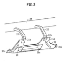
- the occupant knee protection apparatus includes a knee airbag , module 10, which is disposed at a vertical position approximately identical with that of a knee portion B of an occupant A, and is attached to an instrument-panel reinforcement 23 via a panel 21, and paired right-hand and left-hand brackets 22.
- the knee airbag module 10 includes a knee airbag 11 capable of expanding and deploying in front of the knee portion B of the occupant A; an inflator 12 for supplying gas to the knee airbag 11 upon collision of the vehicle; and an airbag case 13 for accommodating the knee airbag 11 and the inflator 12.
- the knee airbag 11 is formed of woven fabric, and is accommodated within the airbag case 13 in a folded condition. Upon collision of the vehicle, as shown in FIG. 1, the knee airbag 11 expands and deploys toward the knee portion B of the occupant A, to thereby protect the knee portion B of the occupant A.
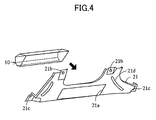
- the airbag case 13 is attached to an opening portion 21 a provided in a lower end portion of the panel 21, and the upper wall portion 13a of the airbag case 13 is superposed on the lower surface of an upper portion of the opening edge of the panel 21.
- the panel 21 is formed from a thin plate into a predetermined shape, and can absorb energy when it undergoes plastic deformation upon receipt of an energy absorption load F1. As shown in FIG. 2, the panel 21 is disposed in front of the position of a knee portion B1 of an occupant whose build is smaller than the standard build such that the knee portion B1 can come into contact with the panel 21.
- the occupant whose build is smaller than the standard build refers to, for example, a person having a small build which corresponds to a build of AF05 for public evaluation; i.e., a build which covers 5% of American adult women.
- Upper end attachment portions 21 b of the panel 21 are connected to rear end portions of the corresponding brackets 22.
- Lower end attachment portions 21 c of the panel 21 are connected to a lower end of an instrument panel 24.
- Vertically extending beads (bulged reinforcement portions) 21 d are formed on the right-hand and left-hand end portions of the panel 21.
- the brackets 22 are formed from a thick plate into a predetermined shape, and can absorb energy when undergoing plastic deformation upon receipt of an energy absorption load F2 (a load greater than the energy absorption load F1 of the panel 21). As shown in FIG. 2, the brackets 22 are disposed in front of the position of a knee portion B2 of an occupant who has the standard build or a build larger than the standard build such that the knee portion B2 can come into contact with the brackets 22.
- the occupant who has the standard build or a build larger than the standard build refers to, for example, a person having a large build which corresponds to a build of AM50 for public evaluation; i.e., a build which covers 50% of American adult men.
- the front ends of the brackets 22 are fixed to the instrument-panel reinforcement 23.
- the brackets 22 have two bent portions at an intermediate portion, at which the brackets 22 bend downward.
- the knee airbag 11 in an ordinary state, the knee airbag 11 is accommodated within the airbag case 13 in a folded condition, and is covered by a rupturable lower portion of the instrument panel 24.
- a corresponding sensor (not shown) detects an acceleration greater than a preset value
- the inflator 12 supplies gas into the knee airbag 11 in a folded condition.
- the knee airbag 11 expands and deploys by the action of the supplied gas, as shown in FIG. 1, the knee airbag 11 enters the space between the knee portion B of the occupant A and the panel 21 and the brackets 22.
- the knee airbag 11 upon collision of the vehicle, the knee airbag 11 expands and deploys toward the knee portion B of the occupant A to thereby receive an impact load of the knee portion B of the occupant A. Further, when the occupant has a small build as compared with the standard build, a portion of the load which the knee airbag 11 has failed to receive is received by the panel 21 disposed in front of the knee portion B1 of the occupant, and then by the brackets 22. When the occupant has the standard build, or a larger build as compared with the standard build, the portion of the load which the knee airbag 11 has failed to receive is received by the brackets 22 disposed in front of the knee portion B2 of the occupant.
- the occupant knee protection apparatus can sufficiently cope with variations in knee positions B1, B2 or load stemming from variation in physique among possible occupants, and can optimally absorb energy.
- a reaction generated when the knee airbag 11 receives the impact load of the knee portion B of the occupant A is received by the instrument-panel reinforcement 23 via the panel 21 and the brackets 22.
- the energy absorption load F2 of the brackets 22 is rendered greater than the energy absorption load F1 of the panel 21. Therefore, when the occupant has a small build as compared with the standard build (i.e., the occupant has a small mass and low body resistance to shock), energy absorption can be effected by means of the panel 21 which deforms with the small load F1, and when the occupant has the standard build or a large build as compared with the standard build (i.e., the occupant has a large mass and high body resistance to shock), energy absorption can be effected by means of the brackets 22 which deform with the high load F2. Therefore, the occupant knee protection apparatus can effectively protect the occupant within a limited space within the vehicle.
- the knee airbag 11 is attached to the panel 21 via the airbag case 13. Therefore, the knee airbag 11 and the airbag case 13 can be commonly used among vehicles which have different body shapes and in which the shapes of the panel 21 and the brackets 22 may be changed in accordance with the position of an occupant or a design.
- the knee airbag module 10 can be commonly used among various vehicles.
- the airbag case 13 is attached to the opening portion 21 a of the panel 21, and, as shown in FIG. 5, the upper wall portion 13a of the airbag case 13 is superposed on a lower surface of the upper portion of the opening edge of the panel 21.
- This configuration is effected in the case where the apparatus is applied for the driver's seat. That is, even when a steering column 31 (indicated by an imaginary line in FIG. 5), which moves forward upon collision of the vehicle, comes into contact with the panel 21 or the airbag case 13, the steering column 31 is unlikely to be caught by the upper wall portion 13a of the airbag case 13, whereby smooth movement of the steering column 31 is enabled.
- the airbag case 13 and the panel 21 are formed of separate members. However, the airbag case 13 may be formed integrally with the panel 21.
- the present invention is applied to the case where the inflator 12 is disposed within the knee airbag 11. However, the present invention can be applied to the case where an inflator is disposed outside a knee airbag, in the same manner as in the above-described embodiment, or with an appropriate modification.
Landscapes
- Engineering & Computer Science (AREA)
- Mechanical Engineering (AREA)
- Air Bags (AREA)
Abstract
Description
Claims (4)
- An occupant knee protection apparatus for a vehicle which includes a knee airbag disposed in front of a knee portion of an occupant and configured to expand and deploy toward the knee portion of the occupant upon collision of the vehicle to thereby protect the knee portion of the occupant, the apparatus being characterized in that the knee airbag is attached to a panel capable of absorbing energy, the panel is connected to a support member of the vehicle via a bracket capable of absorbing energy, the panel is disposed in front of the knee portion of the occupant at a vertical position where the knee portion of the occupant can come into contact with the panel when the occupant has a small build as compared with a standard build, and the bracket is disposed in front of the knee portion of the occupant at a vertical position where the knee portion of the occupant can come into contact with the bracket when the occupant has the standard build or a large build as compared with the standard build.
- An occupant knee protection apparatus for a vehicle according to claim 1, wherein the bracket has an energy absorption load greater than that of the panel.
- An occupant knee protection apparatus for a vehicle according to claim 1 or 2, wherein the knee airbag is attached to the panel via an airbag case.
- An occupant knee protection apparatus for a vehicle according to claim 3, wherein the airbag case is attached to an opening portion of the panel, and an upper wall portion of the airbag case is superposed on a lower surface of an upper portion of an opening edge of the panel.
Applications Claiming Priority (3)
| Application Number | Priority Date | Filing Date | Title |
|---|---|---|---|
| JP2002056363A JP3767497B2 (en) | 2002-03-01 | 2002-03-01 | Vehicle occupant knee protection device |
| JP2002056363 | 2002-03-01 | ||
| PCT/JP2003/001747 WO2003074332A1 (en) | 2002-03-01 | 2003-02-19 | Occupant knee part protective device for vehicle |
Publications (3)
| Publication Number | Publication Date |
|---|---|
| EP1481857A1 true EP1481857A1 (en) | 2004-12-01 |
| EP1481857A4 EP1481857A4 (en) | 2005-04-27 |
| EP1481857B1 EP1481857B1 (en) | 2006-08-30 |
Family
ID=27784635
Family Applications (1)
| Application Number | Title | Priority Date | Filing Date |
|---|---|---|---|
| EP03706960A Expired - Lifetime EP1481857B1 (en) | 2002-03-01 | 2003-02-19 | Occupant knee part protective device for vehicle |
Country Status (8)
| Country | Link |
|---|---|
| US (1) | US7290787B2 (en) |
| EP (1) | EP1481857B1 (en) |
| JP (1) | JP3767497B2 (en) |
| KR (1) | KR100586905B1 (en) |
| CN (1) | CN1319785C (en) |
| AU (1) | AU2003211234A1 (en) |
| DE (1) | DE60307991T2 (en) |
| WO (1) | WO2003074332A1 (en) |
Families Citing this family (11)
| Publication number | Priority date | Publication date | Assignee | Title |
|---|---|---|---|---|
| GB2408239A (en) * | 2003-11-19 | 2005-05-25 | Autoliv Dev | Safety arrangement actuated to restrain forward movement of a vehicle occupant's knees |
| JP4553577B2 (en) * | 2003-12-12 | 2010-09-29 | タカタ株式会社 | Knee bag and occupant leg protection device |
| JP4710862B2 (en) * | 2007-04-02 | 2011-06-29 | 豊田合成株式会社 | Air bag device for knee protection |
| US8308189B2 (en) | 2009-03-10 | 2012-11-13 | Toyota Jidosha Kabushiki Kaisha | Knee airbag for vehicle |
| WO2010151651A2 (en) * | 2009-06-24 | 2010-12-29 | Shape Corp. | Energy absorber with double-acting crush lobes |
| JP5310689B2 (en) * | 2010-09-30 | 2013-10-09 | トヨタ自動車株式会社 | Vehicle occupant knee protection device |
| JP5310688B2 (en) * | 2010-09-30 | 2013-10-09 | トヨタ自動車株式会社 | Vehicle pedal retraction suppression structure |
| MX2016003764A (en) * | 2013-09-27 | 2016-07-08 | Calsonic Kansei Corp | Knee protector structure for vehicle. |
| JP6446908B2 (en) * | 2014-08-20 | 2019-01-09 | Joyson Safety Systems Japan株式会社 | Passenger leg restraining device |
| US10457240B2 (en) * | 2016-11-04 | 2019-10-29 | Magnesium Products Of America | Glove box rail with integrated airbag support |
| JP7087814B2 (en) * | 2018-08-10 | 2022-06-21 | トヨタ自動車株式会社 | Front structure of the passenger compartment |
Family Cites Families (14)
| Publication number | Priority date | Publication date | Assignee | Title |
|---|---|---|---|---|
| GB2218385A (en) | 1988-03-29 | 1989-11-15 | Trw Repa Gmbh | Vehicle passive restraint system with gas bag and knee cushion |
| JPH0256053A (en) | 1988-08-22 | 1990-02-26 | Toshiba Corp | Document preparing device |
| JPH0256053U (en) * | 1988-10-18 | 1990-04-23 | ||
| US4978136A (en) * | 1988-12-19 | 1990-12-18 | Mazda Motor Corporation | Automotive knee protector |
| JPH0632195A (en) * | 1992-07-17 | 1994-02-08 | Nissan Motor Co Ltd | Knee protector device for automobile |
| JPH0732962A (en) | 1993-07-15 | 1995-02-03 | Nissan Motor Co Ltd | Air bag device mounting structure |
| JPH09123857A (en) | 1995-10-27 | 1997-05-13 | Mitsubishi Motors Corp | Airbag device for legs |
| JPH09123863A (en) * | 1995-10-27 | 1997-05-13 | Mitsubishi Motors Corp | Leg protector |
| DE29702797U1 (en) * | 1997-02-18 | 1997-06-12 | Trw Repa Gmbh | Knee restraint for vehicles |
| JP3411480B2 (en) | 1997-08-22 | 2003-06-03 | 本田技研工業株式会社 | Shock absorber |
| JP3838464B2 (en) | 1997-12-25 | 2006-10-25 | スズキ株式会社 | Automotive knee bolster structure |
| JP2002521257A (en) | 1998-07-20 | 2002-07-16 | ティーアールダブリュー・オキュパント・リストレイント・システムズ・ゲーエムベーハー・ウント・コンパニー・カーゲー | Knee restraint system for vehicles |
| DE19950944A1 (en) | 1999-10-22 | 2001-04-26 | Bayerische Motoren Werke Ag | Combination of airbag and additional shock absorbing device for protection of knee of occupant of motor vehicle comprises shock absorbing unit, joined to inner surface of car body at one end |
| JP3772748B2 (en) | 2001-05-21 | 2006-05-10 | 豊田合成株式会社 | Air bag device for knee protection |
-
2002
- 2002-03-01 JP JP2002056363A patent/JP3767497B2/en not_active Expired - Fee Related
-
2003
- 2003-02-19 AU AU2003211234A patent/AU2003211234A1/en not_active Abandoned
- 2003-02-19 DE DE60307991T patent/DE60307991T2/en not_active Expired - Lifetime
- 2003-02-19 US US10/505,949 patent/US7290787B2/en not_active Expired - Fee Related
- 2003-02-19 CN CNB038049856A patent/CN1319785C/en not_active Expired - Fee Related
- 2003-02-19 EP EP03706960A patent/EP1481857B1/en not_active Expired - Lifetime
- 2003-02-19 WO PCT/JP2003/001747 patent/WO2003074332A1/en not_active Ceased
- 2003-02-19 KR KR1020047013553A patent/KR100586905B1/en not_active Expired - Fee Related
Also Published As
| Publication number | Publication date |
|---|---|
| CN1638990A (en) | 2005-07-13 |
| CN1319785C (en) | 2007-06-06 |
| WO2003074332A1 (en) | 2003-09-12 |
| DE60307991T2 (en) | 2007-05-10 |
| EP1481857B1 (en) | 2006-08-30 |
| US7290787B2 (en) | 2007-11-06 |
| KR20040084950A (en) | 2004-10-06 |
| US20050107729A1 (en) | 2005-05-19 |
| JP3767497B2 (en) | 2006-04-19 |
| JP2003252162A (en) | 2003-09-10 |
| DE60307991D1 (en) | 2006-10-12 |
| KR100586905B1 (en) | 2006-06-08 |
| AU2003211234A1 (en) | 2003-09-16 |
| EP1481857A4 (en) | 2005-04-27 |
Similar Documents
| Publication | Publication Date | Title |
|---|---|---|
| US7261318B2 (en) | Knee airbag and glove box assembly | |
| US6712385B2 (en) | Dent and vibration resistant rigid knee airbag | |
| KR101509780B1 (en) | Automobile side air bag unit | |
| US7144032B2 (en) | Expandable pelvic side airbag | |
| CN104024059A (en) | Airbag system for automobile | |
| EP1481857B1 (en) | Occupant knee part protective device for vehicle | |
| KR20030003267A (en) | Passenger protection apparatus for a motor vehicle | |
| US7967327B2 (en) | Knee protection device for vehicle | |
| EP1431131B1 (en) | Vehicle with occupant's leg protection system | |
| JP2000025552A (en) | Shock protective device | |
| JP3261048B2 (en) | Fixed structure of vehicle occupant protection device | |
| JPH03281454A (en) | Air bag device for automobile | |
| KR100512861B1 (en) | Housing having a reinforced structure in a passenger air-bag module | |
| JP5672222B2 (en) | Vehicle occupant restraint system | |
| JPH081154Y2 (en) | Inflator mounting structure in airbag device | |
| JP4529325B2 (en) | Vehicle occupant protection device | |
| KR100397513B1 (en) | connecting device of air bag modul for automobiles | |
| JPH05229392A (en) | Vehicle air bag device with shock absorber | |
| JP5725046B2 (en) | Knee lateral restraint airbag device | |
| KR100512856B1 (en) | Double driver air-bag for a vehicle | |
| KR100750403B1 (en) | Side airbag of car | |
| KR100187820B1 (en) | Airbags in the passenger seat of a car | |
| KR19990005093U (en) | Car airbag structure | |
| KR200141885Y1 (en) | Shock-absorbing structure of airbag provided in passenger seat of car | |
| JP5783187B2 (en) | Knee lateral restraint airbag device |
Legal Events
| Date | Code | Title | Description |
|---|---|---|---|
| PUAI | Public reference made under article 153(3) epc to a published international application that has entered the european phase |
Free format text: ORIGINAL CODE: 0009012 |
|
| 17P | Request for examination filed |
Effective date: 20040903 |
|
| AK | Designated contracting states |
Kind code of ref document: A1 Designated state(s): AT BE BG CH CY CZ DE DK EE ES FI FR GB GR HU IE IT LI LU MC NL PT SE SI SK TR |
|
| AX | Request for extension of the european patent |
Extension state: AL LT LV MK RO |
|
| A4 | Supplementary search report drawn up and despatched |
Effective date: 20050311 |
|
| GRAP | Despatch of communication of intention to grant a patent |
Free format text: ORIGINAL CODE: EPIDOSNIGR1 |
|
| RIC1 | Information provided on ipc code assigned before grant |
Ipc: B60R 21/045 20060101AFI20060301BHEP |
|
| GRAS | Grant fee paid |
Free format text: ORIGINAL CODE: EPIDOSNIGR3 |
|
| GRAA | (expected) grant |
Free format text: ORIGINAL CODE: 0009210 |
|
| AK | Designated contracting states |
Kind code of ref document: B1 Designated state(s): DE FR GB IT |
|
| PG25 | Lapsed in a contracting state [announced via postgrant information from national office to epo] |
Ref country code: IT Free format text: LAPSE BECAUSE OF FAILURE TO SUBMIT A TRANSLATION OF THE DESCRIPTION OR TO PAY THE FEE WITHIN THE PRESCRIBED TIME-LIMIT;WARNING: LAPSES OF ITALIAN PATENTS WITH EFFECTIVE DATE BEFORE 2007 MAY HAVE OCCURRED AT ANY TIME BEFORE 2007. THE CORRECT EFFECTIVE DATE MAY BE DIFFERENT FROM THE ONE RECORDED. Effective date: 20060830 |
|
| REG | Reference to a national code |
Ref country code: GB Ref legal event code: FG4D |
|
| REF | Corresponds to: |
Ref document number: 60307991 Country of ref document: DE Date of ref document: 20061012 Kind code of ref document: P |
|
| ET | Fr: translation filed | ||
| PLBE | No opposition filed within time limit |
Free format text: ORIGINAL CODE: 0009261 |
|
| STAA | Information on the status of an ep patent application or granted ep patent |
Free format text: STATUS: NO OPPOSITION FILED WITHIN TIME LIMIT |
|
| 26N | No opposition filed |
Effective date: 20070531 |
|
| REG | Reference to a national code |
Ref country code: GB Ref legal event code: 746 Effective date: 20110104 |
|
| REG | Reference to a national code |
Ref country code: FR Ref legal event code: PLFP Year of fee payment: 14 |
|
| REG | Reference to a national code |
Ref country code: FR Ref legal event code: PLFP Year of fee payment: 15 |
|
| PGFP | Annual fee paid to national office [announced via postgrant information from national office to epo] |
Ref country code: DE Payment date: 20170214 Year of fee payment: 15 Ref country code: FR Payment date: 20170112 Year of fee payment: 15 |
|
| PGFP | Annual fee paid to national office [announced via postgrant information from national office to epo] |
Ref country code: GB Payment date: 20170215 Year of fee payment: 15 |
|
| PGFP | Annual fee paid to national office [announced via postgrant information from national office to epo] |
Ref country code: IT Payment date: 20170221 Year of fee payment: 15 |
|
| REG | Reference to a national code |
Ref country code: DE Ref legal event code: R119 Ref document number: 60307991 Country of ref document: DE |
|
| GBPC | Gb: european patent ceased through non-payment of renewal fee |
Effective date: 20180219 |
|
| REG | Reference to a national code |
Ref country code: FR Ref legal event code: ST Effective date: 20181031 |
|
| PG25 | Lapsed in a contracting state [announced via postgrant information from national office to epo] |
Ref country code: DE Free format text: LAPSE BECAUSE OF NON-PAYMENT OF DUE FEES Effective date: 20180901 |
|
| PG25 | Lapsed in a contracting state [announced via postgrant information from national office to epo] |
Ref country code: GB Free format text: LAPSE BECAUSE OF NON-PAYMENT OF DUE FEES Effective date: 20180219 Ref country code: FR Free format text: LAPSE BECAUSE OF NON-PAYMENT OF DUE FEES Effective date: 20180228 Ref country code: IT Free format text: LAPSE BECAUSE OF NON-PAYMENT OF DUE FEES Effective date: 20180219 |