EP1481825A1 - Klimaanlage - Google Patents
Klimaanlage Download PDFInfo
- Publication number
- EP1481825A1 EP1481825A1 EP03291283A EP03291283A EP1481825A1 EP 1481825 A1 EP1481825 A1 EP 1481825A1 EP 03291283 A EP03291283 A EP 03291283A EP 03291283 A EP03291283 A EP 03291283A EP 1481825 A1 EP1481825 A1 EP 1481825A1
- Authority
- EP
- European Patent Office
- Prior art keywords
- air
- evaporator
- radiator
- cold
- conditioning system
- Prior art date
- Legal status (The legal status is an assumption and is not a legal conclusion. Google has not performed a legal analysis and makes no representation as to the accuracy of the status listed.)
- Granted
Links
Images
Classifications
-
- B—PERFORMING OPERATIONS; TRANSPORTING
- B60—VEHICLES IN GENERAL
- B60H—ARRANGEMENTS OF HEATING, COOLING, VENTILATING OR OTHER AIR-TREATING DEVICES SPECIALLY ADAPTED FOR PASSENGER OR GOODS SPACES OF VEHICLES
- B60H1/00—Heating, cooling or ventilating devices
- B60H1/00007—Combined heating, ventilating, or cooling devices
- B60H1/00021—Air flow details of HVAC devices
- B60H1/00064—Air flow details of HVAC devices for sending air streams of different temperatures into the passenger compartment
-
- B—PERFORMING OPERATIONS; TRANSPORTING
- B60—VEHICLES IN GENERAL
- B60H—ARRANGEMENTS OF HEATING, COOLING, VENTILATING OR OTHER AIR-TREATING DEVICES SPECIALLY ADAPTED FOR PASSENGER OR GOODS SPACES OF VEHICLES
- B60H1/00—Heating, cooling or ventilating devices
- B60H1/00007—Combined heating, ventilating, or cooling devices
- B60H1/00021—Air flow details of HVAC devices
- B60H1/00035—Air flow details of HVAC devices for sending an air stream of uniform temperature into the passenger compartment
- B60H1/00057—Air flow details of HVAC devices for sending an air stream of uniform temperature into the passenger compartment the air being heated and cooled simultaneously, e.g. using parallel heat exchangers
Definitions
- the invention relates to an air conditioning system, in particular for a motor vehicle, according to the preamble of claim 1.
- flash fogging is a lightning-like misting of the windscreen in Result of high humidity, which is reflected on the cold slices, to prevent.
- these measures are usually quite complex and expensive.
- an air conditioner with an evaporator and a Radiator which are arranged in an air guide housing, designed in such a way that air ducts are provided, directly from the evaporator cold air and / or directly from the radiator warm air to a vent conduct, with the air ducts separated over part of their length are formed, so that in this area no mixture of cold and warm air takes place. Because the air is only the evaporator or Flowing through the radiator, the risk of a "flash fogging" on simple Way reduced or completely prevented.
- the air channels for cold and warm air are formed separately, wherein the air ducts are substantially, that is over a larger part their length, parallel to each other and up to a distribution / mixing unit separated by a wall.
- the evaporator and the radiator are relatively narrow and long trained. This allows optimal air distribution to the individual Air ducts. Are the evaporator and radiator adjacent and arranged substantially parallel to each other in the air duct housing, so the air distribution is further simplified.
- the air ducts can be in one Area where evaporator and radiator are closest to each other Air duct housing are guided, with the cold and the warm air ducts for a vent are preferably arranged at a height.
- vent For adjusting the amount of air and air temperature for each pair of air ducts for hot and cold air is a vent, with this one Can be provided flap or nozzle.
- two parallel air ducts are circular formed, with a wall extending centrally to a distribution / mixing unit.
- the invention is based on an embodiment below Referring to the drawings explained in detail.
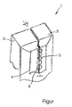
- the only figure of the Drawing shows a simplified view of an air conditioner 1 with a Evaporator 2 and a radiator 3, in an air duct housing 4th are arranged, and schematically illustrated air ducts 5, through which cold and warm air is supplied to the vehicle interior.
- the evaporator 2 and the heater 3 relatively long and narrow and arranged parallel to each other.
- the air channels 5 are after the evaporator 2 and the radiator 3 for cold and separated warm by a wall 6 to a distribution / mixing unit educated. So the air temperature and air volume can be customized for each one Outlets are controlled by a flap (not shown).
- the mixture of cold and warm air takes place in each air duct 5 after the Distributor / mixing unit and upstream of this air duct 5 associated vent separated for each vent.
Landscapes
- Physics & Mathematics (AREA)
- Thermal Sciences (AREA)
- Engineering & Computer Science (AREA)
- Mechanical Engineering (AREA)
- Air-Conditioning For Vehicles (AREA)
- Air-Conditioning Room Units, And Self-Contained Units In General (AREA)
- Air Filters, Heat-Exchange Apparatuses, And Housings Of Air-Conditioning Units (AREA)
Abstract
Description
- 1
- Klimaanlage
- 2
- Verdampfer
- 3
- Heizkörper
- 4
- Luftführungsgehäuse
- 5
- Luftkanal
- 6
- Wand
Claims (6)
- Klimaanlage mit einem Verdampfer (2) und einem Heizkörper (3), die in einem Luftführungsgehäuse (4) angeordnet sind, dadurch gekennzeichnet, dass Luftkanäle (5) vorgesehen sind, die direkt vom Verdampfer (2) aus kalte Luft und/oder direkt vom Heizkörper (3) aus warme Luft zu einem Ausströmer leiten.
- Klimaanlage nach Anspruch 1, dadurch gekennzeichnet, dass die Luftkanäle (5) für kalte und warme Luft getrennt ausgebildet sind, wobei die Luftkanäle (5) im Wesentlichen parallel zueinander verlaufen und bis zu einer Verteiler-/Mischeinheit durch eine Wand (6) getrennt sind.
- Klimaanlage nach Anspruch 1 oder 2, dadurch gekennzeichnet, dass der Verdampfer (2) und der Heizkörper (3) relativ schmal und lang ausgebildet sind.
- Anlage nach einem der vorhergehenden Ansprüche, dadurch gekennzeichnet, dass der Verdampfer (2) und der Heizkörper (3) benachbart und im Wesentlichen parallel zueinander im Luftführungsgehäuse (4) angeordnet sind.
- Anlage nach einem der vorhergehenden Ansprüche, dadurch gekennzeichnet, dass zur Einstellung der Luftmenge und Lufttemperatur für jedes Paar von Luftkanälen (5) für warme und kalte Luft ein Ausströmer dient.
- Anlage nach einem der vorhergehenden Ansprüche, dadurch gekennzeichnet, dass zwei parallel zueinander verlaufende Luftkanäle (5) kreisförmig ausgebildet sind, wobei eine Wand (6) mittig verläuft.
Priority Applications (3)
| Application Number | Priority Date | Filing Date | Title |
|---|---|---|---|
| AT03291283T ATE353782T1 (de) | 2003-05-27 | 2003-05-27 | Klimaanlage |
| DE50306496T DE50306496D1 (de) | 2003-05-27 | 2003-05-27 | Klimaanlage |
| EP03291283A EP1481825B1 (de) | 2003-05-27 | 2003-05-27 | Klimaanlage |
Applications Claiming Priority (1)
| Application Number | Priority Date | Filing Date | Title |
|---|---|---|---|
| EP03291283A EP1481825B1 (de) | 2003-05-27 | 2003-05-27 | Klimaanlage |
Publications (2)
| Publication Number | Publication Date |
|---|---|
| EP1481825A1 true EP1481825A1 (de) | 2004-12-01 |
| EP1481825B1 EP1481825B1 (de) | 2007-02-14 |
Family
ID=33104211
Family Applications (1)
| Application Number | Title | Priority Date | Filing Date |
|---|---|---|---|
| EP03291283A Expired - Lifetime EP1481825B1 (de) | 2003-05-27 | 2003-05-27 | Klimaanlage |
Country Status (3)
| Country | Link |
|---|---|
| EP (1) | EP1481825B1 (de) |
| AT (1) | ATE353782T1 (de) |
| DE (1) | DE50306496D1 (de) |
Cited By (1)
| Publication number | Priority date | Publication date | Assignee | Title |
|---|---|---|---|---|
| DE102023110366A1 (de) | 2023-04-24 | 2024-10-24 | Audi Aktiengesellschaft | Verfahren zum Kühlen eines Schwarzdruck-Anzeigesystems eines Kraftfahrzeugs, sowie Anordnung und Kraftfahrzeug |
Citations (3)
| Publication number | Priority date | Publication date | Assignee | Title |
|---|---|---|---|---|
| DE1780075B1 (de) * | 1966-05-14 | 1970-07-23 | Opel Adam Ag | In oder in der Naehe der Armaturentafel eines Kraftfahrzeuges vorgesehene Luftleitduese |
| DE2210212A1 (de) * | 1972-03-03 | 1973-09-13 | Bosch Gmbh Robert | Einrichtung zum konstanthalten der temperatur im innenraum eines kraftfahrzeuges |
| DE10101551A1 (de) * | 2001-01-15 | 2002-07-18 | Delphi Tech Inc | Versorgungsmodul für Kraftfahrzeugklimaanlagen |
-
2003
- 2003-05-27 AT AT03291283T patent/ATE353782T1/de not_active IP Right Cessation
- 2003-05-27 DE DE50306496T patent/DE50306496D1/de not_active Expired - Lifetime
- 2003-05-27 EP EP03291283A patent/EP1481825B1/de not_active Expired - Lifetime
Patent Citations (3)
| Publication number | Priority date | Publication date | Assignee | Title |
|---|---|---|---|---|
| DE1780075B1 (de) * | 1966-05-14 | 1970-07-23 | Opel Adam Ag | In oder in der Naehe der Armaturentafel eines Kraftfahrzeuges vorgesehene Luftleitduese |
| DE2210212A1 (de) * | 1972-03-03 | 1973-09-13 | Bosch Gmbh Robert | Einrichtung zum konstanthalten der temperatur im innenraum eines kraftfahrzeuges |
| DE10101551A1 (de) * | 2001-01-15 | 2002-07-18 | Delphi Tech Inc | Versorgungsmodul für Kraftfahrzeugklimaanlagen |
Cited By (2)
| Publication number | Priority date | Publication date | Assignee | Title |
|---|---|---|---|---|
| DE102023110366A1 (de) | 2023-04-24 | 2024-10-24 | Audi Aktiengesellschaft | Verfahren zum Kühlen eines Schwarzdruck-Anzeigesystems eines Kraftfahrzeugs, sowie Anordnung und Kraftfahrzeug |
| WO2024223275A1 (de) | 2023-04-24 | 2024-10-31 | Audi Ag | Verfahren zum kühlen eines schwarzdruck-anzeigesystems eines kraftfahrzeugs, sowie anordnung und kraftfahrzeug |
Also Published As
| Publication number | Publication date |
|---|---|
| EP1481825B1 (de) | 2007-02-14 |
| DE50306496D1 (de) | 2007-03-29 |
| ATE353782T1 (de) | 2007-03-15 |
Similar Documents
| Publication | Publication Date | Title |
|---|---|---|
| EP0841201B2 (de) | Heiz- oder Klimaanlage für ein Kraftfahrzeug | |
| DE102009057814B4 (de) | Klimaanlage für Fahrzeuge | |
| DE10037384A1 (de) | Heizungs- und Klimaanlage für ein Kraftfahrzeug | |
| DE102015110559B4 (de) | Luftverteilungssystem für die dritte und/oder vierte Zone eines Drei- oder Vierzonen-Kraftfahrzeugklimagerätes | |
| DE10057039A1 (de) | Heizungs- oder Klimaanlage für ein Kraftfahrzeug | |
| EP1369268A2 (de) | Verfahren zur Bereitstellung von temperierter Luft und für dieses verwendbare Vorrichtung | |
| DE102014224817B4 (de) | Klimaanlage | |
| DE102009044760B4 (de) | Klimaanlage für ein Kraftfahrzeug | |
| DE102004033856B4 (de) | Klimaanlage für Fahrzeuge | |
| DE4422120C2 (de) | Heizungs- oder Klimaanlage für ein Kraftfahrzeug | |
| DE10328275A1 (de) | Heizungs- und/oder Klimaanlage für ein Kraftfahrzeug | |
| DE60221007T2 (de) | Heizungs-, belüftungs- und/oder klimaanlagen | |
| DE102004042287B4 (de) | Fahrzeugtemperatursteuersystem | |
| DE102014109925A1 (de) | Mehrzonen-Klimatisierungseinrichtung | |
| DE10147113B4 (de) | Vorrichtung zum Temperieren und Belüften von Kraftfahrzeugen | |
| EP1481825B1 (de) | Klimaanlage | |
| DE102018117968B4 (de) | Luftverteileinrichtung für eine Mehrzonen-Klimaanlage und Mehrzonen-Klimaanlage für Kraftfahrzeuge | |
| EP1510375B1 (de) | Klimaanlage sowie Verfahren zum Betreiben einer solchen | |
| EP1636056B1 (de) | Bauanordnung für eine klimaanlage | |
| DE19835286B4 (de) | Heizungs- oder Klimaanlage eines Fahrzeuges | |
| EP2011676B1 (de) | Klimaanlage | |
| EP1571019B1 (de) | Klimatisierungsvorrichtung, insbesondere für ein Krafffahrzeug | |
| DE19953498C1 (de) | Heizungs- oder Klimaanlage für Fahrzeuge | |
| EP2088011A1 (de) | Gehäuse-Anordnung für eine Fahrzeugklimaanlage | |
| EP1741581B1 (de) | Fondbelüftungs-, Heizungs- oder Klimaanlage |
Legal Events
| Date | Code | Title | Description |
|---|---|---|---|
| PUAI | Public reference made under article 153(3) epc to a published international application that has entered the european phase |
Free format text: ORIGINAL CODE: 0009012 |
|
| AK | Designated contracting states |
Kind code of ref document: A1 Designated state(s): AT BE BG CH CY CZ DE DK EE ES FI FR GB GR HU IE IT LI LU MC NL PT RO SE SI SK TR |
|
| AX | Request for extension of the european patent |
Extension state: AL LT LV MK |
|
| 17P | Request for examination filed |
Effective date: 20050601 |
|
| AKX | Designation fees paid |
Designated state(s): AT BE BG CH CY CZ DE DK EE ES FI FR GB GR HU IE IT LI LU MC NL PT RO SE SI SK TR |
|
| RAP1 | Party data changed (applicant data changed or rights of an application transferred) |
Owner name: BEHR FRANCE ROUFFACH SAS |
|
| GRAP | Despatch of communication of intention to grant a patent |
Free format text: ORIGINAL CODE: EPIDOSNIGR1 |
|
| GRAS | Grant fee paid |
Free format text: ORIGINAL CODE: EPIDOSNIGR3 |
|
| GRAA | (expected) grant |
Free format text: ORIGINAL CODE: 0009210 |
|
| AK | Designated contracting states |
Kind code of ref document: B1 Designated state(s): AT BE BG CH CY CZ DE DK EE ES FI FR GB GR HU IE IT LI LU MC NL PT RO SE SI SK TR |
|
| PG25 | Lapsed in a contracting state [announced via postgrant information from national office to epo] |
Ref country code: FI Free format text: LAPSE BECAUSE OF FAILURE TO SUBMIT A TRANSLATION OF THE DESCRIPTION OR TO PAY THE FEE WITHIN THE PRESCRIBED TIME-LIMIT Effective date: 20070214 Ref country code: SI Free format text: LAPSE BECAUSE OF FAILURE TO SUBMIT A TRANSLATION OF THE DESCRIPTION OR TO PAY THE FEE WITHIN THE PRESCRIBED TIME-LIMIT Effective date: 20070214 Ref country code: NL Free format text: LAPSE BECAUSE OF FAILURE TO SUBMIT A TRANSLATION OF THE DESCRIPTION OR TO PAY THE FEE WITHIN THE PRESCRIBED TIME-LIMIT Effective date: 20070214 Ref country code: DK Free format text: LAPSE BECAUSE OF FAILURE TO SUBMIT A TRANSLATION OF THE DESCRIPTION OR TO PAY THE FEE WITHIN THE PRESCRIBED TIME-LIMIT Effective date: 20070214 Ref country code: IE Free format text: LAPSE BECAUSE OF FAILURE TO SUBMIT A TRANSLATION OF THE DESCRIPTION OR TO PAY THE FEE WITHIN THE PRESCRIBED TIME-LIMIT Effective date: 20070214 |
|
| REG | Reference to a national code |
Ref country code: GB Ref legal event code: FG4D Free format text: NOT ENGLISH |
|
| REG | Reference to a national code |
Ref country code: CH Ref legal event code: EP |
|
| REF | Corresponds to: |
Ref document number: 50306496 Country of ref document: DE Date of ref document: 20070329 Kind code of ref document: P |
|
| REG | Reference to a national code |
Ref country code: IE Ref legal event code: FG4D Free format text: LANGUAGE OF EP DOCUMENT: GERMAN |
|
| PG25 | Lapsed in a contracting state [announced via postgrant information from national office to epo] |
Ref country code: SE Free format text: LAPSE BECAUSE OF FAILURE TO SUBMIT A TRANSLATION OF THE DESCRIPTION OR TO PAY THE FEE WITHIN THE PRESCRIBED TIME-LIMIT Effective date: 20070514 |
|
| PG25 | Lapsed in a contracting state [announced via postgrant information from national office to epo] |
Ref country code: BG Free format text: LAPSE BECAUSE OF EXPIRATION OF PROTECTION Effective date: 20070515 |
|
| PG25 | Lapsed in a contracting state [announced via postgrant information from national office to epo] |
Ref country code: ES Free format text: LAPSE BECAUSE OF FAILURE TO SUBMIT A TRANSLATION OF THE DESCRIPTION OR TO PAY THE FEE WITHIN THE PRESCRIBED TIME-LIMIT Effective date: 20070525 |
|
| PG25 | Lapsed in a contracting state [announced via postgrant information from national office to epo] |
Ref country code: PT Free format text: LAPSE BECAUSE OF FAILURE TO SUBMIT A TRANSLATION OF THE DESCRIPTION OR TO PAY THE FEE WITHIN THE PRESCRIBED TIME-LIMIT Effective date: 20070716 |
|
| NLV1 | Nl: lapsed or annulled due to failure to fulfill the requirements of art. 29p and 29m of the patents act | ||
| ET | Fr: translation filed | ||
| GBV | Gb: ep patent (uk) treated as always having been void in accordance with gb section 77(7)/1977 [no translation filed] |
Effective date: 20070214 |
|
| REG | Reference to a national code |
Ref country code: IE Ref legal event code: FD4D |
|
| PG25 | Lapsed in a contracting state [announced via postgrant information from national office to epo] |
Ref country code: GB Free format text: LAPSE BECAUSE OF FAILURE TO SUBMIT A TRANSLATION OF THE DESCRIPTION OR TO PAY THE FEE WITHIN THE PRESCRIBED TIME-LIMIT Effective date: 20070214 Ref country code: SK Free format text: LAPSE BECAUSE OF FAILURE TO SUBMIT A TRANSLATION OF THE DESCRIPTION OR TO PAY THE FEE WITHIN THE PRESCRIBED TIME-LIMIT Effective date: 20070214 |
|
| PLBE | No opposition filed within time limit |
Free format text: ORIGINAL CODE: 0009261 |
|
| STAA | Information on the status of an ep patent application or granted ep patent |
Free format text: STATUS: NO OPPOSITION FILED WITHIN TIME LIMIT |
|
| BERE | Be: lapsed |
Owner name: BEHR FRANCE ROUFFACH SAS Effective date: 20070531 |
|
| PG25 | Lapsed in a contracting state [announced via postgrant information from national office to epo] |
Ref country code: RO Free format text: LAPSE BECAUSE OF FAILURE TO SUBMIT A TRANSLATION OF THE DESCRIPTION OR TO PAY THE FEE WITHIN THE PRESCRIBED TIME-LIMIT Effective date: 20070214 Ref country code: CZ Free format text: LAPSE BECAUSE OF FAILURE TO SUBMIT A TRANSLATION OF THE DESCRIPTION OR TO PAY THE FEE WITHIN THE PRESCRIBED TIME-LIMIT Effective date: 20070214 |
|
| REG | Reference to a national code |
Ref country code: CH Ref legal event code: PL |
|
| 26N | No opposition filed |
Effective date: 20071115 |
|
| PG25 | Lapsed in a contracting state [announced via postgrant information from national office to epo] |
Ref country code: MC Free format text: LAPSE BECAUSE OF NON-PAYMENT OF DUE FEES Effective date: 20070531 |
|
| PG25 | Lapsed in a contracting state [announced via postgrant information from national office to epo] |
Ref country code: CH Free format text: LAPSE BECAUSE OF NON-PAYMENT OF DUE FEES Effective date: 20070531 Ref country code: LI Free format text: LAPSE BECAUSE OF NON-PAYMENT OF DUE FEES Effective date: 20070531 |
|
| PG25 | Lapsed in a contracting state [announced via postgrant information from national office to epo] |
Ref country code: BE Free format text: LAPSE BECAUSE OF NON-PAYMENT OF DUE FEES Effective date: 20070531 |
|
| PG25 | Lapsed in a contracting state [announced via postgrant information from national office to epo] |
Ref country code: GR Free format text: LAPSE BECAUSE OF FAILURE TO SUBMIT A TRANSLATION OF THE DESCRIPTION OR TO PAY THE FEE WITHIN THE PRESCRIBED TIME-LIMIT Effective date: 20070515 Ref country code: IT Free format text: LAPSE BECAUSE OF FAILURE TO SUBMIT A TRANSLATION OF THE DESCRIPTION OR TO PAY THE FEE WITHIN THE PRESCRIBED TIME-LIMIT Effective date: 20070214 |
|
| PG25 | Lapsed in a contracting state [announced via postgrant information from national office to epo] |
Ref country code: AT Free format text: LAPSE BECAUSE OF NON-PAYMENT OF DUE FEES Effective date: 20070527 |
|
| PG25 | Lapsed in a contracting state [announced via postgrant information from national office to epo] |
Ref country code: EE Free format text: LAPSE BECAUSE OF FAILURE TO SUBMIT A TRANSLATION OF THE DESCRIPTION OR TO PAY THE FEE WITHIN THE PRESCRIBED TIME-LIMIT Effective date: 20070214 |
|
| PG25 | Lapsed in a contracting state [announced via postgrant information from national office to epo] |
Ref country code: CY Free format text: LAPSE BECAUSE OF FAILURE TO SUBMIT A TRANSLATION OF THE DESCRIPTION OR TO PAY THE FEE WITHIN THE PRESCRIBED TIME-LIMIT Effective date: 20070214 |
|
| PG25 | Lapsed in a contracting state [announced via postgrant information from national office to epo] |
Ref country code: LU Free format text: LAPSE BECAUSE OF NON-PAYMENT OF DUE FEES Effective date: 20070527 |
|
| PG25 | Lapsed in a contracting state [announced via postgrant information from national office to epo] |
Ref country code: HU Free format text: LAPSE BECAUSE OF FAILURE TO SUBMIT A TRANSLATION OF THE DESCRIPTION OR TO PAY THE FEE WITHIN THE PRESCRIBED TIME-LIMIT Effective date: 20070815 Ref country code: TR Free format text: LAPSE BECAUSE OF FAILURE TO SUBMIT A TRANSLATION OF THE DESCRIPTION OR TO PAY THE FEE WITHIN THE PRESCRIBED TIME-LIMIT Effective date: 20070214 |
|
| PGFP | Annual fee paid to national office [announced via postgrant information from national office to epo] |
Ref country code: FR Payment date: 20100617 Year of fee payment: 8 |
|
| PGFP | Annual fee paid to national office [announced via postgrant information from national office to epo] |
Ref country code: DE Payment date: 20100602 Year of fee payment: 8 |
|
| REG | Reference to a national code |
Ref country code: FR Ref legal event code: ST Effective date: 20120131 |
|
| REG | Reference to a national code |
Ref country code: DE Ref legal event code: R119 Ref document number: 50306496 Country of ref document: DE Effective date: 20111201 |
|
| PG25 | Lapsed in a contracting state [announced via postgrant information from national office to epo] |
Ref country code: FR Free format text: LAPSE BECAUSE OF NON-PAYMENT OF DUE FEES Effective date: 20110531 |
|
| PG25 | Lapsed in a contracting state [announced via postgrant information from national office to epo] |
Ref country code: DE Free format text: LAPSE BECAUSE OF NON-PAYMENT OF DUE FEES Effective date: 20111201 |