EP1481777A2 - Roll exit assembly for cutting off machine - Google Patents
Roll exit assembly for cutting off machine Download PDFInfo
- Publication number
- EP1481777A2 EP1481777A2 EP20040008724 EP04008724A EP1481777A2 EP 1481777 A2 EP1481777 A2 EP 1481777A2 EP 20040008724 EP20040008724 EP 20040008724 EP 04008724 A EP04008724 A EP 04008724A EP 1481777 A2 EP1481777 A2 EP 1481777A2
- Authority
- EP
- European Patent Office
- Prior art keywords
- exit assembly
- roll
- roll exit
- chain
- cutting
- Prior art date
- Legal status (The legal status is an assumption and is not a legal conclusion. Google has not performed a legal analysis and makes no representation as to the accuracy of the status listed.)
- Withdrawn
Links
- 239000000463 material Substances 0.000 claims abstract description 8
- 230000005540 biological transmission Effects 0.000 claims description 6
- 230000001360 synchronised effect Effects 0.000 claims description 5
- 239000004809 Teflon Substances 0.000 claims description 3
- 229920006362 Teflon® Polymers 0.000 claims description 3
- 239000004411 aluminium Substances 0.000 claims description 3
- 229910052782 aluminium Inorganic materials 0.000 claims description 3
- XAGFODPZIPBFFR-UHFFFAOYSA-N aluminium Chemical compound [Al] XAGFODPZIPBFFR-UHFFFAOYSA-N 0.000 claims description 3
- 230000008878 coupling Effects 0.000 claims 1
- 238000010168 coupling process Methods 0.000 claims 1
- 238000005859 coupling reaction Methods 0.000 claims 1
- 238000009966 trimming Methods 0.000 description 5
- 230000033001 locomotion Effects 0.000 description 3
- 238000004519 manufacturing process Methods 0.000 description 2
- 238000005259 measurement Methods 0.000 description 2
- 229910052751 metal Inorganic materials 0.000 description 2
- 239000002184 metal Substances 0.000 description 2
- 230000000903 blocking effect Effects 0.000 description 1
- 230000001419 dependent effect Effects 0.000 description 1
- 239000002699 waste material Substances 0.000 description 1
Images


Classifications
-
- B—PERFORMING OPERATIONS; TRANSPORTING
- B26—HAND CUTTING TOOLS; CUTTING; SEVERING
- B26D—CUTTING; DETAILS COMMON TO MACHINES FOR PERFORATING, PUNCHING, CUTTING-OUT, STAMPING-OUT OR SEVERING
- B26D7/00—Details of apparatus for cutting, cutting-out, stamping-out, punching, perforating, or severing by means other than cutting
- B26D7/06—Arrangements for feeding or delivering work of other than sheet, web, or filamentary form
- B26D7/0625—Arrangements for feeding or delivering work of other than sheet, web, or filamentary form by endless conveyors, e.g. belts
-
- B—PERFORMING OPERATIONS; TRANSPORTING
- B26—HAND CUTTING TOOLS; CUTTING; SEVERING
- B26D—CUTTING; DETAILS COMMON TO MACHINES FOR PERFORATING, PUNCHING, CUTTING-OUT, STAMPING-OUT OR SEVERING
- B26D7/00—Details of apparatus for cutting, cutting-out, stamping-out, punching, perforating, or severing by means other than cutting
- B26D7/01—Means for holding or positioning work
- B26D2007/013—Means for holding or positioning work the work being tubes, rods or logs
-
- B—PERFORMING OPERATIONS; TRANSPORTING
- B26—HAND CUTTING TOOLS; CUTTING; SEVERING
- B26D—CUTTING; DETAILS COMMON TO MACHINES FOR PERFORATING, PUNCHING, CUTTING-OUT, STAMPING-OUT OR SEVERING
- B26D2210/00—Machines or methods used for cutting special materials
- B26D2210/11—Machines or methods used for cutting special materials for cutting web rolls
Definitions
- the present invention relates to a roll exit assembly for a cutting off machine for the transverse cutting of rolls of sheet material, such as paper, starting from large-sized logs.
- the roll exit assembly serves to remove cut rolls from the cutting area.
- the log of paper to be cut is made to advance on the cutting off machine bench by means of a pusher towards a cutting disc, as described in European patent application EP0970784 in the name of the same applicant.
- the advancement of the log, under the action of the pusher pushes the cut roll onto a roll discharge belt whilst the trimming or end waste is pushed directly by the pusher.
- FIG. 1 illustrates a roll exit assembly 101 according to the prior art destined to be disposed downstream of a conveying bed 102 of a cutting off machine.
- rolls 103 of sheet material obtained by transverse cutting of a log, are fed toward the roll exit assembly 101 by means of a pusher 104 moved along the conveying bed 102 of the cutting off machine.
- the roll exit assembly 101 comprises a belt conveyor having two flat belts 105 and two belts 106 with a circular section.
- the flat belts 105 allow conveying of rolls in a vertical or raised position (not shown in Figures 1 and 2), that is to say with the axis of the roll at right angles to the conveying surface, whilst the belts 106 with a circular section, as shown in Figures 1 and 2, allow conveying of rolls 103 in a horizontal or lying position, that is to say with the axis of the roll parallel to the conveying surface.
- Said roll exit assembly 101 according to the prior art presents many drawbacks.
- the distance between the two circular section belts 106 is fixed, with the consequent limitation of the minimum and maximum diameters of the roll 103 to be conveyed, according to the distance between said belts. In fact, small diameter rolls sink too deep between the belts, whilst large diameter rolls are not gripped adequately.
- the width of the pusher 104 is limited by the distance between the two circular section belts 106 and this does not allow an adequate surface for pushing and pressing the log, especially in the case of large diameter logs.
- the end trimmings of the rolls with a high diameter/height (transverse measurement/axial measurement) ratio can rotate around the pusher 104 in the cutting area because of the friction between the log and the pressers (elements for blocking the log in the cutting area) during advancement of the log and/or because of the stress exerted by the cutting disk on the log during cutting.
- a height difference is generated between the log on the conveying bench 102 of the cutting off machine and the roll 103 on the roll exit assembly 101.
- the difference varies with the diameter of the roll and will be greater for small diameter rolls and smaller for large diameter rolls.
- the object of the present invention is to eliminate the drawbacks of the prior art by providing a roll exit assembly for a cutting off machine that is versatile and able to work with rolls of different diameters and formats.
- Another object of the present invention is to provide a roll exit assembly that is highly reliable and able to avoid risks of jamming of the machine.
- Yet another object of the present invention is to provide a roll exit assembly that is able to allow continuous high-speed production, without the need to stop components of the machine.
- the roll exit assembly comprises a conveyor consisting of two chains, belts or other conveying means which may support inserts of aluminium, Teflon or other material, of a suitable shape to grip the roll in a vertical or in a horizontal position.
- the chains are mounted on supports which can translate along a straight line, so as to keep constant the angle formed between the contact surfaces of the inserts of the two chains and to adapt the gripping width according to the diameter of the roll.
- the two chains thus form an ideal V-shaped support to accommodate the roll.
- the angle of opening of this V-shaped support is identical to that of the support bench of the cutting off machine. Thus, a height difference between the log on the bench and the roll on the exit assembly is avoided.
- FIG. 3 illustrates partially a cutting off machine, indicated as a whole with reference numeral 10.
- the cutting off machine 10 comprises a conveying bench 2, a cutting assembly 20 and a roll exit assembly 1.
- a log 30 of large length is conveyed on the conveying bench 2 towards the cutting assembly 20.
- the cutting assembly 20 comprises an arm 21 supporting a rotating disc 22 to perform the transverse cutting of the log 30 into rolls of smaller length.
- the roll 3 obtained by cutting the log 30 is pushed, by means of pushers 4, towards the roll exit assembly 1 which, by means of a conveying system 50, is responsible for conveying the rolls 3 towards roll discharge means. Movement of the pushers 4 takes place by means of a chain transmission in a per se known manner.
- the roll exit assembly 1 comprises a base frame 40 supported by feet 41 and disposed downstream of the cutting assembly 20.
- the base frame 40 supports the conveying system 50 and a conveyor belt 42 disposed downstream of the conveying system 50 to allow the discharge of the rolls 3 from the cutting off machine 10.
- the conveying system 50 comprises a support frame 51 to be mounted fixedly to the base frame 40.
- the support frame 51 On the sides of the support frame 51 there are provided two transmission track chains 60, disposed longitudinally and parallel to each other.
- conveying and drive transmission means such as belts and the like-able to support the cut rolls can be provided instead of the chains 60.
- Each chain 60 is supported by two pinions 62 and 63.
- the first pinion 62 is shrunk on a shaft mounted idly in a plate 66 carrying the chain 60.
- the second pinion 63 is shrunk on a drive shaft 64 set in rotation by an electric motor 65 disposed beyond the chain-carrying plate 66.
- each insert 61 has, towards the outside, a first face 61a substantially parallel with respect to a plane passing through the axes of rotation of the pinions 62 and 63 and a second face 61b substantially oblique with respect to said plane passing through the axes of rotation of the pinions 62 and 63.
- the support frame 51 has on each side a pair of support brackets 52 disposed obliquely with respect to a horizontal plane and converging with each other.
- the chain-carrying plates 66 are mounted on the respective support brackets 52 of the frame 51.
- the flat faces 61a of the inserts 61 of the chains are disposed obliquely with respect to a horizontal plane and diverge from each other, so as to form a substantially V-shaped seat able to receive the rolls 3 in a horizontal position.
- the oblique faces 61b of the inserts are disposed along a plane substantially parallel to the horizontal plane to receive the edges of a roll disposed vertically.
- the support frame 51 has a fixed structure comprising two sides 54 connected to a front crossbar 57.
- Two rear crossbars 58 are connected to the respective sides 54.
- two rods 59 connect the respective rear crossbars 58 to the front crossbar 57.
- Each movable structure consists of two support brackets 52, of an abutment plate 53 and of two slides or shoes 55.
- the shoes 55 are mounted slidably in a pair of grooved guides 56 integral with the front crossbar 57 and with the rear crossbars 58 of the support frame 51. In this manner each abutment plate 53 is maintained parallel to the respective side 54.
- the grooved guides 56 are substantially oblique with respect to a horizontal plane.
- each side 54 there is mounted a handwheel 70 which sets in rotation a screw 71 which passes through the respective side 54 to engage in a nut-screw formed in the abutment plate 53 of the mobile structure.
- the screw 71 which screws into the nut-screw of the abutment plate 53 is set in rotation.
- the shoes 55 which are integral with the abutment plate 53, slide linearly in the respective guides 56.
- the support brackets 52 move along a trajectory imposed by the guides 56.
- the chain-carrying plates 66 are integral with the respective pairs of brackets 52, by operating the handwheels 70 the distance between the chains 60 can be adjusted so as to adapt the conveying system 50 to the different diameters of the rolls 3 to be conveyed. With this system rolls 3 with diameters ranging from 90 mm to 350 mm can be conveyed.
- the movement of the chain-carrying plates 66 is synchronised.
- a pulley 73 which draws a respective belt 74 into rotation is shrunk on the shank of each screw 71.
- the belt 74 in turn sets in rotation another pulley 75 provided at the end of a synchronisation shaft 76.
- a gear 77 which meshes with a corresponding gear 77 or with an universal joint of the other synchronisation shaft 76.
- an automatic adjustment system such as an electric motor that sets the screw 71 in rotation could be provided, or an actuator that pushes the mobile structure could be provided in place of the screw and nut-screw system.
- the motors 65 that set the respective chains 60 in motion are synchronised with each other by means of a suitable inverter actuator, so as to allow synchronous rotation of the chains 60.
- a single motor and drive transmission means to transmit the drive to both chains 60 can be provided instead of the two motors 65.
- the speed of advancement of the chains 60 is controlled so as to be greater than the speed of advancement of the pushers 4 to allow a rapid removal of the rolls 3 from the area of rotation of the pushers 4.
- the bench for conveying rolls 2 leaving the cutting assembly 20 has a cradle-shaped support guide 8 obtained by means of suitably inclined metal plates.
- the chains 60 are adjusted in position, so that the front face of the inserts 61 is kept in register with and substantially parallel to the plane of the guide metal plates 8. In this manner the passage of the roll 3 from the guide 8 of the conveying bench to the chains 60 of the conveying system 50 of the exit assembly 1 is facilitated.
- the conveying system 50 of the roll exit assembly 1 is particularly suitable for also conveying rolls 3 in the vertical position, that is to say with the axis of the roll at right angles to the conveying surface.
- the edges of the roll 3 rest on the oblique faces 61b of the inserts 61 of the chains.
- the pusher 4 consists of a plate supported by a flange 90 mounted on a carriage 91 slidable in guides 93 of the conveying bench.
- the front end of the conveying bench 2 ends in register with the front end of the cradle-shaped guide 8. Therefore the pusher 4, when it reaches the front end of the conveying bench 2, that is to say at the end of its working stroke, pushes the roll 3 between the chains 60 of the roll exit assembly to begin rotation and its return stroke.
- the pushing plate of the pusher 4 can be chosen sufficiently wide to be able to pass in the space between the two chains 60. In this manner a larger surface for pushing the log 30 is ensured.
- the invention is not limited to said embodiment.
- the inserts 61 are optional and can therefore be omitted.
- the chains 60 can be replaced by other conveying means, such as, for example, belts and the like.
Abstract
Description
- The present invention relates to a roll exit assembly for a cutting off machine for the transverse cutting of rolls of sheet material, such as paper, starting from large-sized logs.
- The roll exit assembly serves to remove cut rolls from the cutting area. The log of paper to be cut is made to advance on the cutting off machine bench by means of a pusher towards a cutting disc, as described in European patent application EP0970784 in the name of the same applicant. The advancement of the log, under the action of the pusher, pushes the cut roll onto a roll discharge belt whilst the trimming or end waste is pushed directly by the pusher.
- Figure 1 illustrates a
roll exit assembly 101 according to the prior art destined to be disposed downstream of aconveying bed 102 of a cutting off machine. In this manner, rolls 103 of sheet material, obtained by transverse cutting of a log, are fed toward theroll exit assembly 101 by means of apusher 104 moved along theconveying bed 102 of the cutting off machine. - With reference also to Figure 2, the
roll exit assembly 101 comprises a belt conveyor having twoflat belts 105 and twobelts 106 with a circular section. Theflat belts 105 allow conveying of rolls in a vertical or raised position (not shown in Figures 1 and 2), that is to say with the axis of the roll at right angles to the conveying surface, whilst thebelts 106 with a circular section, as shown in Figures 1 and 2, allow conveying ofrolls 103 in a horizontal or lying position, that is to say with the axis of the roll parallel to the conveying surface. - Said
roll exit assembly 101 according to the prior art presents many drawbacks. - The distance between the two
circular section belts 106 is fixed, with the consequent limitation of the minimum and maximum diameters of theroll 103 to be conveyed, according to the distance between said belts. In fact, small diameter rolls sink too deep between the belts, whilst large diameter rolls are not gripped adequately. - When the
pusher 104, in order to make the return stroke, rotates around the pinion which transmits drive to the belts, if theroll exit assembly 101 does not carry out an efficient and rapid evacuation of the trimming, impact of the pusher with the last trimming may occur. For this reason, both thepusher 104 and the arm that supports the cutting disk are stopped for the time necessary for removal of the trimming from the range of thepusher 104. - The width of the
pusher 104 is limited by the distance between the twocircular section belts 106 and this does not allow an adequate surface for pushing and pressing the log, especially in the case of large diameter logs. - Because of the small width of the
pusher 104, the end trimmings of the rolls with a high diameter/height (transverse measurement/axial measurement) ratio can rotate around thepusher 104 in the cutting area because of the friction between the log and the pressers (elements for blocking the log in the cutting area) during advancement of the log and/or because of the stress exerted by the cutting disk on the log during cutting. - Furthermore, a height difference is generated between the log on the
conveying bench 102 of the cutting off machine and theroll 103 on theroll exit assembly 101. The difference varies with the diameter of the roll and will be greater for small diameter rolls and smaller for large diameter rolls. - The object of the present invention is to eliminate the drawbacks of the prior art by providing a roll exit assembly for a cutting off machine that is versatile and able to work with rolls of different diameters and formats.
- Another object of the present invention is to provide a roll exit assembly that is highly reliable and able to avoid risks of jamming of the machine.
- Yet another object of the present invention is to provide a roll exit assembly that is able to allow continuous high-speed production, without the need to stop components of the machine.
- These objects are achieved in accordance with the invention with the characteristics listed in appended
independent claim 1. - Advantageous embodiments of the invention are apparent from the dependent claims.
- The roll exit assembly according to the invention comprises a conveyor consisting of two chains, belts or other conveying means which may support inserts of aluminium, Teflon or other material, of a suitable shape to grip the roll in a vertical or in a horizontal position.
- The chains are mounted on supports which can translate along a straight line, so as to keep constant the angle formed between the contact surfaces of the inserts of the two chains and to adapt the gripping width according to the diameter of the roll. The two chains thus form an ideal V-shaped support to accommodate the roll. The angle of opening of this V-shaped support is identical to that of the support bench of the cutting off machine. Thus, a height difference between the log on the bench and the roll on the exit assembly is avoided.
- This exit assembly according to the invention presents various advantages:
- The possibility of carrying out adjustment of the distance between the chains so as to achieve ideal gripping and discharge of the roll.
- An increase in the range of roll diameters that can be conveyed.
- The possibility of installing pushers of a width optimal for the diameter of the roll in production. Problems of incorrect pushing and the possibility that the roll might rotate around the pusher in the cutting area because of the friction between the log and the pressers during feeding of the log and/or because of the stress exerted on the log by the cutting disc during cutting are thus eliminated.
- It is not necessary to stop the pusher to ensure evacuation of the roll by the exit assembly since the optimal gripping of the roll by the inserts allows a rapid discharge thereof by simple adjustment of the speed of the chains (which is greater than that of the pusher).
- The height difference between the log on the bench and the roll on the exit assembly is eliminated by means of the translation and the adjustment of the chains and a greater stability of the roll in the passage from the cutting off machine bench to the roll exit assembly is thus achieved.
- Further characteristics of the invention will be made clearer by the detailed description that follows, referring to a purely exemplary and therefore non-limiting embodiment thereof, illustrated in the appended drawings, in which:
- Figure 1 is a partially broken off perspective view illustrating a roll exit assembly according to the prior art disposed downstream of a cutting off machine, in which the cutting assembly has been omitted;
- Figure 2 is a cross sectional view of the roll exit assembly of Figure 1;
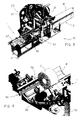
- Figure 3 is a perspective view, partially illustrating a cutting off machine provided with a roll exit assembly according to the invention;
- Figure 4 is an enlarged view of a detail of the roll exit assembly of Figure 1, in the situation of conveying a roll disposed horizontally with the axis parallel to the conveying surface;
- Figure 4a is a view like that of Figure 4, but in the situation of conveying a roll disposed vertically with the axis at right angles to the conveying surface;
- Figure 5 is a perspective view of the exit assembly of Figure 4 seen from the rear;
- Figure 6 is an enlarged, partially broken off, cross sectional view of the exit assembly of Figure 4;
- Figure 6a is a view like that of Figure 6, but illustrating the situation in which the roll is disposed vertically;
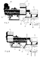
- Figure 7 is a longitudinal sectional view of the roll exit assembly of Figure 4;
- Figure 8 is a view like Figure 7, but illustrating the condition of rotation of the pusher when it reaches the end of the working stroke;
- Figure 9 is a perspective exploded view of a support frame and of a conveyor chain forming part of the conveyor of the roll exit assembly according to the invention;
- Figure 10 is a perspective view illustrating the assembled conveyor of the roll exit assembly according to the invention.
- Figure 3 illustrates partially a cutting off machine, indicated as a whole with
reference numeral 10. The cutting offmachine 10 comprises aconveying bench 2, acutting assembly 20 and aroll exit assembly 1. - A
log 30 of large length is conveyed on the conveyingbench 2 towards thecutting assembly 20. Thecutting assembly 20 comprises anarm 21 supporting a rotatingdisc 22 to perform the transverse cutting of thelog 30 into rolls of smaller length. - As shown in Figures 4, 5 and 7, the
roll 3 obtained by cutting thelog 30 is pushed, by means ofpushers 4, towards theroll exit assembly 1 which, by means of aconveying system 50, is responsible for conveying therolls 3 towards roll discharge means. Movement of thepushers 4 takes place by means of a chain transmission in a per se known manner. - Coming back to Figure 3, the
roll exit assembly 1 comprises abase frame 40 supported byfeet 41 and disposed downstream of thecutting assembly 20. Thebase frame 40 supports theconveying system 50 and aconveyor belt 42 disposed downstream of theconveying system 50 to allow the discharge of therolls 3 from the cutting offmachine 10. - As shown better in Figures 9 and 10, the
conveying system 50 comprises asupport frame 51 to be mounted fixedly to thebase frame 40. On the sides of thesupport frame 51 there are provided twotransmission track chains 60, disposed longitudinally and parallel to each other. - Obviously, other conveying and drive transmission means - such as belts and the like-able to support the cut rolls can be provided instead of the
chains 60. - On the links or on the tracks of the
chains 60 there are mountedinserts 61 of a material such as Teflon, aluminium, polizene or other material having a different coefficient of friction, depending upon the product to be removed. - Each
chain 60 is supported by twopinions first pinion 62 is shrunk on a shaft mounted idly in aplate 66 carrying thechain 60. Thesecond pinion 63 is shrunk on adrive shaft 64 set in rotation by anelectric motor 65 disposed beyond the chain-carryingplate 66. - It should be noted (Figure 6) that each
insert 61 has, towards the outside, afirst face 61a substantially parallel with respect to a plane passing through the axes of rotation of thepinions second face 61b substantially oblique with respect to said plane passing through the axes of rotation of thepinions - The
support frame 51 has on each side a pair ofsupport brackets 52 disposed obliquely with respect to a horizontal plane and converging with each other. The chain-carryingplates 66 are mounted on therespective support brackets 52 of theframe 51. In this manner theflat faces 61a of theinserts 61 of the chains are disposed obliquely with respect to a horizontal plane and diverge from each other, so as to form a substantially V-shaped seat able to receive therolls 3 in a horizontal position. On the other hand, the oblique faces 61b of the inserts are disposed along a plane substantially parallel to the horizontal plane to receive the edges of a roll disposed vertically. - Coming back to Figure 9, the
support frame 51 has a fixed structure comprising twosides 54 connected to afront crossbar 57. Tworear crossbars 58 are connected to the respective sides 54. To strengthen the fixed structure, tworods 59 connect the respectiverear crossbars 58 to thefront crossbar 57. - Two movable structures are mounted on this fixed structure. Each movable structure consists of two
support brackets 52, of anabutment plate 53 and of two slides or shoes 55. Theshoes 55 are mounted slidably in a pair ofgrooved guides 56 integral with thefront crossbar 57 and with therear crossbars 58 of thesupport frame 51. In this manner eachabutment plate 53 is maintained parallel to therespective side 54. The grooved guides 56 are substantially oblique with respect to a horizontal plane. - In each
side 54 there is mounted ahandwheel 70 which sets in rotation ascrew 71 which passes through therespective side 54 to engage in a nut-screw formed in theabutment plate 53 of the mobile structure. In this manner, by turning thehandwheel 70, thescrew 71 which screws into the nut-screw of theabutment plate 53 is set in rotation. Thus theshoes 55, which are integral with theabutment plate 53, slide linearly in the respective guides 56. As a result, thesupport brackets 52 move along a trajectory imposed by theguides 56. - Since the chain-carrying
plates 66 are integral with the respective pairs ofbrackets 52, by operating thehandwheels 70 the distance between thechains 60 can be adjusted so as to adapt the conveyingsystem 50 to the different diameters of therolls 3 to be conveyed. With this system rolls 3 with diameters ranging from 90 mm to 350 mm can be conveyed. - The movement of the chain-carrying
plates 66 is synchronised. For this purpose, a pulley 73 which draws a respective belt 74 into rotation is shrunk on the shank of eachscrew 71. The belt 74 in turn sets in rotation anotherpulley 75 provided at the end of asynchronisation shaft 76. At the other end of thesynchronisation shaft 76 there is provided agear 77 which meshes with acorresponding gear 77 or with an universal joint of theother synchronisation shaft 76. In this way, by turning one of the twohandwheels 70, the two chain-carryingplates 66 are moved synchronously and at the same time. - Obviously, in place of the manual adjustment system, consisting of the two
handwheels 70, for adjusting the distance between thechains 60, an automatic adjustment system, such as an electric motor that sets thescrew 71 in rotation could be provided, or an actuator that pushes the mobile structure could be provided in place of the screw and nut-screw system. - The
motors 65 that set therespective chains 60 in motion are synchronised with each other by means of a suitable inverter actuator, so as to allow synchronous rotation of thechains 60. - Obviously, a single motor and drive transmission means to transmit the drive to both
chains 60 can be provided instead of the twomotors 65. - In any case the speed of advancement of the
chains 60 is controlled so as to be greater than the speed of advancement of thepushers 4 to allow a rapid removal of therolls 3 from the area of rotation of thepushers 4. - As shown in Figures 4, 5, 6, the bench for conveying
rolls 2 leaving the cuttingassembly 20 has a cradle-shapedsupport guide 8 obtained by means of suitably inclined metal plates. As can be seen clearly in Figure 6, thanks to the above-mentioned distance adjustment system, thechains 60 are adjusted in position, so that the front face of theinserts 61 is kept in register with and substantially parallel to the plane of theguide metal plates 8. In this manner the passage of theroll 3 from theguide 8 of the conveying bench to thechains 60 of the conveyingsystem 50 of theexit assembly 1 is facilitated. - Furthermore, as shown in Figures 4a e 6a, the conveying
system 50 of theroll exit assembly 1 is particularly suitable for also conveyingrolls 3 in the vertical position, that is to say with the axis of the roll at right angles to the conveying surface. In fact, in this case the edges of theroll 3 rest on the oblique faces 61b of theinserts 61 of the chains. - Furthermore, as shown in Figures 7 and 8, the
pusher 4 consists of a plate supported by aflange 90 mounted on acarriage 91 slidable inguides 93 of the conveying bench. The front end of the conveyingbench 2 ends in register with the front end of the cradle-shapedguide 8. Therefore thepusher 4, when it reaches the front end of the conveyingbench 2, that is to say at the end of its working stroke, pushes theroll 3 between thechains 60 of the roll exit assembly to begin rotation and its return stroke. - As a result, the
chains 60, which have a higher speed with respect to that of thepushers 4, pull theroll 3. Therefore, as shown in Figure 8, when thepusher 4 begins its rotation at the end of the conveyingbench 2, theroll 3 is already at such a distance as not to interfere with thepusher 4. - Furthermore, thanks to the system for adjusting the distance of the
chains 60, the pushing plate of thepusher 4 can be chosen sufficiently wide to be able to pass in the space between the twochains 60. In this manner a larger surface for pushing thelog 30 is ensured. - Even if specific reference has been made in the present description to the
chains 60 and to theinserts 61 mounted on the chains, the invention is not limited to said embodiment. In fact, theinserts 61 are optional and can therefore be omitted. Furthermore, thechains 60 can be replaced by other conveying means, such as, for example, belts and the like.
Claims (12)
- A roll exit assembly (1) for a cutting-off machine (10) comprising a conveyor (50) to convey towards a discharge rolls of sheet material (3) obtained by transverse cutting of large-sized logs (30), characterised in that said conveyor (50) comprises a pair of conveying means (60) supported by respective support means (66, 52, 53, 55) mounted slidably on linear guides (56) integral with the frame of the machine, so as to be able to translate linearly to adjust the distance between said conveying means (60) according to the diameter and to the disposition of the rolls (3) to be conveyed.
- A roll exit assembly (1) according to claim 1, characterised in that said conveying means comprise a pair of chains (60).
- A roll exit assembly (1) according to claim 2, characterised in that inserts (61) of material - such as aluminium, Teflon, polizene and the like - having a coefficient of friction suited to the roll to be conveyed are fixed to the tracks of said chains (60).
- A roll exit assembly (1) according to claim 3, characterised in that said inserts (61) have, in their outward facing part, a first face (61a) parallel to a plane passing through the axes of rotation of the chain (60) and a second face (61b) oblique with respect to said plane passing through the axes of rotation of the chain (60).
- A roll exit assembly (1) according to any one of the preceding claims, characterised in that said conveying means (60) are driven in rotation by means of respective independent motorizations (65) synchronised with each other.
- A roll exit assembly (1) according to any one of claims 1 to 4, characterised in that said conveying means (60) are driven in rotation by means of drive transmission means actuated by a single motorization.
- A roll exit assembly (1) according to any one of claims 2 to 6, characterised in that said chain (60) is mounted on a first idle pinion (62) and on a second motorised pinion (63), wherein both pinions are supported rotatably by said support means (66).
- A roll exit assembly (1) according to any one of the preceding claims, characterised in that said support means of the conveying means (60) are driven by means of manually operated or motorized drive means (71).
- A roll exit assembly (1) according to claim 8, characterised in that said drive means comprise a screw (71) - nut-screw coupling system, wherein the screw is mounted rotatably in the fixed frame (51) of the machine and the nut-screw is formed in said support means (66) of the chain (60).
- A roll exit assembly (1) according to claim 8 or 9, characterised in that said drive means (71) of the chain support means are synchronised with each other by means of synchronisation means.
- A roll exit assembly (1) according to claim 10, characterised in that said synchronisation means comprise belt transmissions (74) which take their drive from the respective drive means (71) and transmit it to respective synchronisation shafts (76) which have respective gears or universal joint (77) meshing with each other.
- A roll exit assembly (1) according to any one of claims 9 to 11, characterised in that said chain support means comprise:an abutment plate (53) in which the nut-screw which couples with said screw driving means (71) is formed;a pair of shoes (55) integral with the abutment plate (53) and mounted slidably in said guides (56) integral with the fixed frame (51);a pair of brackets (52) integral with the abutment plate (53) and disposed obliquely with respect to the shoes (55); anda chain-carrying plate (66) fixed to said brackets (52) and supporting the shafts of the pinions (62, 63) of the chain (60).
Applications Claiming Priority (2)
| Application Number | Priority Date | Filing Date | Title |
|---|---|---|---|
| ITMI20031050 | 2003-05-26 | ||
| IT001050A ITMI20031050A1 (en) | 2003-05-26 | 2003-05-26 | ROLLS OUTLET GROUP FOR CUTTING MACHINE |
Publications (2)
| Publication Number | Publication Date |
|---|---|
| EP1481777A2 true EP1481777A2 (en) | 2004-12-01 |
| EP1481777A3 EP1481777A3 (en) | 2005-06-08 |
Family
ID=30131080
Family Applications (1)
| Application Number | Title | Priority Date | Filing Date |
|---|---|---|---|
| EP04008724A Withdrawn EP1481777A3 (en) | 2003-05-26 | 2004-04-13 | Roll exit assembly for cutting off machine |
Country Status (2)
| Country | Link |
|---|---|
| EP (1) | EP1481777A3 (en) |
| IT (1) | ITMI20031050A1 (en) |
Cited By (8)
| Publication number | Priority date | Publication date | Assignee | Title |
|---|---|---|---|---|
| FR2917662A1 (en) * | 2007-06-21 | 2008-12-26 | Eberle Soc Par Actions Simplif | Tube supporting and driving device for cutting machine, has motorized longitudinal assemblies symmetrically placed on both sides of vertical plane passing via longitudinal axis of tube and symmetrically inclined relative to vertical plane |
| CN106965237A (en) * | 2017-05-12 | 2017-07-21 | 北塘区军之印纸品加工厂 | A kind of paper roll processing shearing servicing unit |
| ITUA20163298A1 (en) * | 2016-05-10 | 2017-11-10 | Paper Converting Machine Company Italia S P A | CUTTING MACHINE AND CUTTING METHOD OF ROLLS OF MATERIAL IN SHEET |
| CN109129026A (en) * | 2018-10-24 | 2019-01-04 | 深圳格瑞克机械有限公司 | Penholder automatic cutter |
| CN112092031A (en) * | 2020-07-17 | 2020-12-18 | 保定市碧柔卫生用品有限公司 | Roll toilet paper cutting device |
| CN112623329A (en) * | 2020-12-10 | 2021-04-09 | 杭州中亚机械股份有限公司 | A plunger device for filling line |
| CN116079806A (en) * | 2023-04-07 | 2023-05-09 | 颐中(潍坊)实业有限公司 | Slitting machine with adjustable biax web |
| CN116160100A (en) * | 2023-04-21 | 2023-05-26 | 中建材(合肥)钢构科技有限公司 | Plasma cutting device for automatic steel pipe feeding |
Families Citing this family (3)
| Publication number | Priority date | Publication date | Assignee | Title |
|---|---|---|---|---|
| CN108515727B (en) * | 2018-03-28 | 2019-07-19 | 江苏南江智能装备股份有限公司 | A kind of portable molding machine of chain-type papery and portable forming method |
| CN109129663A (en) * | 2018-09-27 | 2019-01-04 | 盐城市华森机械有限公司 | A kind of sand paper automatic die cutter |
| CN117656141B (en) * | 2024-02-01 | 2024-04-05 | 青州金青云新材料有限公司 | Device is tailor to aluminized paper |
Citations (5)
| Publication number | Priority date | Publication date | Assignee | Title |
|---|---|---|---|---|
| US4265361A (en) * | 1979-10-10 | 1981-05-05 | American Can Company | Apparatus for handling wound rolls of fibrous webs |
| GB2137918A (en) * | 1983-03-18 | 1984-10-17 | Lucchese Finanz | A Device for Removing Scrap |
| EP0607761A1 (en) * | 1992-09-28 | 1994-07-27 | FABIO PERINI S.p.A. | Trim removing apparatus associated with a cutting-off machine for the formation of small rolls of toilet paper or the like |
| EP0970785A1 (en) * | 1998-07-07 | 2000-01-12 | Italconverting srl | Device for automatic elimination of scraps in the manufacture of rolls of paper |
| WO2003106122A1 (en) * | 2002-06-13 | 2003-12-24 | Fabio Perini S.P.A. | Device for eliminating end trimmings from a roll or the like |
-
2003
- 2003-05-26 IT IT001050A patent/ITMI20031050A1/en unknown
-
2004
- 2004-04-13 EP EP04008724A patent/EP1481777A3/en not_active Withdrawn
Patent Citations (5)
| Publication number | Priority date | Publication date | Assignee | Title |
|---|---|---|---|---|
| US4265361A (en) * | 1979-10-10 | 1981-05-05 | American Can Company | Apparatus for handling wound rolls of fibrous webs |
| GB2137918A (en) * | 1983-03-18 | 1984-10-17 | Lucchese Finanz | A Device for Removing Scrap |
| EP0607761A1 (en) * | 1992-09-28 | 1994-07-27 | FABIO PERINI S.p.A. | Trim removing apparatus associated with a cutting-off machine for the formation of small rolls of toilet paper or the like |
| EP0970785A1 (en) * | 1998-07-07 | 2000-01-12 | Italconverting srl | Device for automatic elimination of scraps in the manufacture of rolls of paper |
| WO2003106122A1 (en) * | 2002-06-13 | 2003-12-24 | Fabio Perini S.P.A. | Device for eliminating end trimmings from a roll or the like |
Cited By (11)
| Publication number | Priority date | Publication date | Assignee | Title |
|---|---|---|---|---|
| FR2917662A1 (en) * | 2007-06-21 | 2008-12-26 | Eberle Soc Par Actions Simplif | Tube supporting and driving device for cutting machine, has motorized longitudinal assemblies symmetrically placed on both sides of vertical plane passing via longitudinal axis of tube and symmetrically inclined relative to vertical plane |
| ITUA20163298A1 (en) * | 2016-05-10 | 2017-11-10 | Paper Converting Machine Company Italia S P A | CUTTING MACHINE AND CUTTING METHOD OF ROLLS OF MATERIAL IN SHEET |
| EP3243612A1 (en) * | 2016-05-10 | 2017-11-15 | Paper Converting Machine Company Italia S.p.A. | Cutting machine and method of cutting rolls of sheet material |
| CN106965237A (en) * | 2017-05-12 | 2017-07-21 | 北塘区军之印纸品加工厂 | A kind of paper roll processing shearing servicing unit |
| CN109129026A (en) * | 2018-10-24 | 2019-01-04 | 深圳格瑞克机械有限公司 | Penholder automatic cutter |
| CN112092031A (en) * | 2020-07-17 | 2020-12-18 | 保定市碧柔卫生用品有限公司 | Roll toilet paper cutting device |
| CN112623329A (en) * | 2020-12-10 | 2021-04-09 | 杭州中亚机械股份有限公司 | A plunger device for filling line |
| CN112623329B (en) * | 2020-12-10 | 2023-11-14 | 杭州中亚机械股份有限公司 | Rod inserting device for filling production line |
| CN116079806A (en) * | 2023-04-07 | 2023-05-09 | 颐中(潍坊)实业有限公司 | Slitting machine with adjustable biax web |
| CN116160100A (en) * | 2023-04-21 | 2023-05-26 | 中建材(合肥)钢构科技有限公司 | Plasma cutting device for automatic steel pipe feeding |
| CN116160100B (en) * | 2023-04-21 | 2023-06-27 | 中建材(合肥)钢构科技有限公司 | Plasma cutting device for automatic steel pipe feeding |
Also Published As
| Publication number | Publication date |
|---|---|
| EP1481777A3 (en) | 2005-06-08 |
| ITMI20031050A1 (en) | 2004-11-27 |
| ITMI20031050A0 (en) | 2003-05-26 |
Similar Documents
| Publication | Publication Date | Title |
|---|---|---|
| EP1481777A2 (en) | Roll exit assembly for cutting off machine | |
| WO2015194983A1 (en) | Machine with an endless band-knife for cutting sponge panels into pieces | |
| JP4383573B2 (en) | Cutting machine for automatic cutting of printed matter such as temporary binding book, magazine or book | |
| ITFI20060064A1 (en) | MOBILE BRIDGE BAND SAW FOR AXIAL CUTTING OF BARS OR METAL TUBES | |
| KR101011716B1 (en) | Do coutting slice stacking apparatus in high speed slicer | |
| CN215698420U (en) | Continuous plate shearing machine for plate processing | |
| US4750254A (en) | Continuously operating one-sided formatting and edge shaping machine | |
| KR910008902B1 (en) | Dimpleless tube cutting apparatus | |
| JP2017052091A (en) | Slice cutting method of long workpiece and apparatus therefor, v-groove slice cutting method of long pipe material and apparatus therefor, and portable type slice cutting machine | |
| US6067884A (en) | Part cutting machine | |
| JP4463281B2 (en) | Strip plate processing equipment | |
| CA2687357C (en) | Transport device for a finger jointing system | |
| JP2662375B2 (en) | Sheet metal processing machine | |
| CN216938626U (en) | Shearing device for steel strip processing line | |
| CN219684140U (en) | Band sawing machine with multi-section cutting function | |
| CN215395530U (en) | Automatic splitting machine for product processing | |
| CN217512940U (en) | Steel plate shearing machine | |
| CN112004649B (en) | Method, apparatus and blade arrangement for cutting logs | |
| CN216803692U (en) | Material pulling device based on automatic production of swim ring | |
| CN115251125B (en) | Meat product's section device | |
| CN116140694B (en) | Conveying equipment for shearing aluminum plates | |
| CN217292604U (en) | Mechanism is cut in conductive sheet processing | |
| CN219818194U (en) | Novel roll-cutting type plate shearing machine | |
| CN218488614U (en) | Feeding mechanism of wood door and door pocket cutting equipment | |
| CN215247890U (en) | Sheet material horizontal and vertical grooving machine |
Legal Events
| Date | Code | Title | Description |
|---|---|---|---|
| PUAI | Public reference made under article 153(3) epc to a published international application that has entered the european phase |
Free format text: ORIGINAL CODE: 0009012 |
|
| AK | Designated contracting states |
Kind code of ref document: A2 Designated state(s): AT BE BG CH CY CZ DE DK EE ES FI FR GB GR HU IE IT LI LU MC NL PL PT RO SE SI SK TR |
|
| AX | Request for extension of the european patent |
Extension state: AL HR LT LV MK |
|
| PUAL | Search report despatched |
Free format text: ORIGINAL CODE: 0009013 |
|
| AK | Designated contracting states |
Kind code of ref document: A3 Designated state(s): AT BE BG CH CY CZ DE DK EE ES FI FR GB GR HU IE IT LI LU MC NL PL PT RO SE SI SK TR |
|
| AX | Request for extension of the european patent |
Extension state: AL HR LT LV MK |
|
| RIN1 | Information on inventor provided before grant (corrected) |
Inventor name: BIAGIONI, MAURO Inventor name: CASELLA, SERGIO |
|
| 17P | Request for examination filed |
Effective date: 20051115 |
|
| AKX | Designation fees paid |
Designated state(s): AT BE BG CH CY CZ DE DK EE ES FI FR GB GR HU IE IT LI LU MC NL PL PT RO SE SI SK TR |
|
| 17Q | First examination report despatched |
Effective date: 20061206 |
|
| STAA | Information on the status of an ep patent application or granted ep patent |
Free format text: STATUS: THE APPLICATION IS DEEMED TO BE WITHDRAWN |
|
| 18D | Application deemed to be withdrawn |
Effective date: 20080624 |