EP1481715A1 - Center tube for filters - Google Patents
Center tube for filters Download PDFInfo
- Publication number
- EP1481715A1 EP1481715A1 EP20040253067 EP04253067A EP1481715A1 EP 1481715 A1 EP1481715 A1 EP 1481715A1 EP 20040253067 EP20040253067 EP 20040253067 EP 04253067 A EP04253067 A EP 04253067A EP 1481715 A1 EP1481715 A1 EP 1481715A1
- Authority
- EP
- European Patent Office
- Prior art keywords
- central portion
- center tube
- discs
- filter
- tube assembly
- Prior art date
- Legal status (The legal status is an assumption and is not a legal conclusion. Google has not performed a legal analysis and makes no representation as to the accuracy of the status listed.)
- Withdrawn
Links
Images


Classifications
-
- B—PERFORMING OPERATIONS; TRANSPORTING
- B01—PHYSICAL OR CHEMICAL PROCESSES OR APPARATUS IN GENERAL
- B01D—SEPARATION
- B01D27/00—Cartridge filters of the throw-away type
- B01D27/04—Cartridge filters of the throw-away type with cartridges made of a piece of unitary material, e.g. filter paper
- B01D27/06—Cartridge filters of the throw-away type with cartridges made of a piece of unitary material, e.g. filter paper with corrugated, folded or wound material
-
- B—PERFORMING OPERATIONS; TRANSPORTING
- B01—PHYSICAL OR CHEMICAL PROCESSES OR APPARATUS IN GENERAL
- B01D—SEPARATION
- B01D2201/00—Details relating to filtering apparatus
- B01D2201/04—Supports for the filtering elements
- B01D2201/0415—Details of supporting structures
-
- B—PERFORMING OPERATIONS; TRANSPORTING
- B01—PHYSICAL OR CHEMICAL PROCESSES OR APPARATUS IN GENERAL
- B01D—SEPARATION
- B01D2201/00—Details relating to filtering apparatus
- B01D2201/12—Pleated filters
- B01D2201/127—Pleated filters with means for keeping the spacing between the pleats
-
- B—PERFORMING OPERATIONS; TRANSPORTING
- B01—PHYSICAL OR CHEMICAL PROCESSES OR APPARATUS IN GENERAL
- B01D—SEPARATION
- B01D2201/00—Details relating to filtering apparatus
- B01D2201/40—Special measures for connecting different parts of the filter
- B01D2201/4023—Means for connecting filter housings to supports
-
- Y—GENERAL TAGGING OF NEW TECHNOLOGICAL DEVELOPMENTS; GENERAL TAGGING OF CROSS-SECTIONAL TECHNOLOGIES SPANNING OVER SEVERAL SECTIONS OF THE IPC; TECHNICAL SUBJECTS COVERED BY FORMER USPC CROSS-REFERENCE ART COLLECTIONS [XRACs] AND DIGESTS
- Y10—TECHNICAL SUBJECTS COVERED BY FORMER USPC
- Y10T—TECHNICAL SUBJECTS COVERED BY FORMER US CLASSIFICATION
- Y10T428/00—Stock material or miscellaneous articles
- Y10T428/13—Hollow or container type article [e.g., tube, vase, etc.]
- Y10T428/1352—Polymer or resin containing [i.e., natural or synthetic]
- Y10T428/139—Open-ended, self-supporting conduit, cylinder, or tube-type article
Definitions
- This invention relates to a filter for use in fluid systems, and more particularly, the invention relates to a center tube commonly used in filters.
- Filters are typically constructed from a housing of one or more components secured to one another.
- a filter media which is typically a pleated type filter media, is disposed within the interior cavity of the housing.
- the filter media is typically cylindrical in shape with the exterior of the filter media defining an input side through which dirty fluid enters.
- the interior of the filter media defines an outlet side that receives the clean fluid.
- a center tube is typically arranged centrally within the filter relative to the filter media to hold the shape of the filter media and provide strength to the filter.
- the center tube is typically constructed from metal. Center tubes of different diameters and lengths are produced for various sized filters. As a result, a high inventory of center tubes is required for the different filters. Furthermore, numerous individual dies, rollers and sealing equipment are required for producing each of the center tubes for the various filters.
- a filter for a fluid system includes a housing having an interior cavity.
- a filter media is disposed in the housing and defines a central opening.
- a center tube assembly is arranged within the central opening and includes discs which are stackable upon one another. Each disc includes a central portion having base received by an inner wall of the central portion of the adjacent disc. An outer portion extends radially outwardly from the central portion and is positioned adjacent to the filter media. The central portion, base, and outer portion may include openings to permit the flow of fluid through the center tube assembly.
- the center tube assembly provides the desired structural integrity while permitting fluid to flow through the center tube.
- the present invention center tube assembly may be produced by a plastic molding process.
- the above provides a center tube that permits the flow of oil therethrough while being able to accommodate different diameters and lengths needed for the various filters.
- a filter 10, shown in Figure 1 is typically used for filtering fluid such as in a lubrication system for an engine.
- the filter 10 includes a can or housing 12 that may be constructed from one or more components secured to one another.
- a nut plate 14 may be secured to an outer cylindrical wall portion with a seam 18.
- An O-ring 16 is placed on the nut plate 14 to seal between the filter 10 and a mounting adaptor (not shown).
- the filter 10 includes an interior cavity 20 with a filter media 24 disposed within the cavity interior 20 to filter debris from the fluid so that clean fluid may be returned to the engine, such as for lubrication of engine components.
- the filter media 24 may be of a generally cylindrical shape and is typically pleated to form inner edges 25 that define a central opening 27.
- the filter media 24 is typically retained between end caps, which are not shown for clarity.
- the filter media 24 has an inlet side 26 that receives dirty fluid and an outlet side 28 where clean fluid exits the filter media 24.
- the nut plate 14 may include perforations 22 to permit dirty fluid to enter the filter 10.
- Nut plate 14 may also include a threaded aperture 34 that is used to secure the filter 10 to the mounting adaptor. The clean fluid exits the central opening 27 through the threaded aperture 34 and into the mounting adaptor.
- the present invention center tube assembly may also be used with a cartridge type filter typically located within a suitable fixed housing.
- the filter media is retained between spaced apart end discs, such that the outer perimeter of the filter media is left exposed.
- Such a filter arrangement is well known in the art.
- the present invention center tube assembly discussed below, may be used in any suitable filter configuration.
- a center tube assembly 35 is disposed within the central opening 27 to provide structural integrity to the filter 10 and permit fluid to pass through the center tube assembly 35 to the mounting adaptor.
- the center tube assembly 35 is arranged proximate to the filter media 24 to provide support to its inner edges 25 to maintain the shape of the filter media 24.
- the center tube assembly 35 includes discs 36 that are stacked to a desired height. Referring to Figures 2-4, the center tube assembly 35 includes a central portion 37 that may be any desirable shape.
- the central portion 37 may include spaced apart vertical walls 38 defining openings 39.
- the central portion 37 further includes a base 40 that is indented or recessed radially from the vertical walls 38 and is received by an inner wall 41 of the adjacent disc 36.
- the base 40 includes arms 42 extending between the vertical walls 38 to provide structural rigidity.
- the arms 42 define openings 43 to permit the flow of fluid therethrough.
- An outer portion 46 may extend radially outwardly from the central portion 37.
- the outer portion 46 includes an annular wall 52 connected to the central portion 37 by legs 50.
- the legs 50, annular wall 52, and central portion 37 define openings 53 that permit the flow of fluid therethrough.
- Fins 44 may be interconnected between the central portion 37 and the outer portion 46 to provide additional structural rigidity to the discs 36.
- the length of the central portion 37 may be varied to provide different length discs 36 suitable for multiple filters. Moreover, a combination of discs 36 having different length central portions 37 may be used to achieve a desired length of the center tube assembly 35. Similarly, different size outer portions 46 may also be used to provide various diameters of the center tube assembly 35, as best shown in Figure 5.
- the center tube assembly 35 of the present invention is constructed from a plastic.
- the center tube assembly 35 may be produced by a molding process.
- a dedicated mold may be used to produce a disc having a defined central portion length and outer portion diameter.
- Various molds may be used to provide sets of various sized discs that may be mixed or matched to provide a center tube assembly of a desired length and diameter.
- a mold may contain various inserts to provide different length central portions 37 and different diameters of the outer portion 46 so that only one mold may be needed, as will be appreciated of one of ordinary skilled in the art.
- the disc 36 shown in Figure 5 may be trimmed to provide a disc 36 of the diameter shown in Figure 4 so that one mold may provide discs of different diameters.
- a more versatile mold may be used having inserts to vary the central portion length and outer portion diameter, as would be appreciated by one of ordinary skilled in the art.
Landscapes
- Chemical & Material Sciences (AREA)
- Chemical Kinetics & Catalysis (AREA)
- Lubrication Details And Ventilation Of Internal Combustion Engines (AREA)
- Filtration Of Liquid (AREA)
- Filtering Materials (AREA)
- Separation Using Semi-Permeable Membranes (AREA)
- Extrusion Moulding Of Plastics Or The Like (AREA)
Abstract
Description
- This invention relates to a filter for use in fluid systems, and more particularly, the invention relates to a center tube commonly used in filters.
- Filters are typically constructed from a housing of one or more components secured to one another. A filter media, which is typically a pleated type filter media, is disposed within the interior cavity of the housing. The filter media is typically cylindrical in shape with the exterior of the filter media defining an input side through which dirty fluid enters. The interior of the filter media defines an outlet side that receives the clean fluid.
- A center tube is typically arranged centrally within the filter relative to the filter media to hold the shape of the filter media and provide strength to the filter. The center tube is typically constructed from metal. Center tubes of different diameters and lengths are produced for various sized filters. As a result, a high inventory of center tubes is required for the different filters. Furthermore, numerous individual dies, rollers and sealing equipment are required for producing each of the center tubes for the various filters.
- Therefore, what is needed is a center tube that permits the flow of fluid therethrough while being able to accommodate different diameters and lengths needed for the various filters.
- A filter for a fluid system includes a housing having an interior cavity. A filter media is disposed in the housing and defines a central opening. A center tube assembly is arranged within the central opening and includes discs which are stackable upon one another. Each disc includes a central portion having base received by an inner wall of the central portion of the adjacent disc. An outer portion extends radially outwardly from the central portion and is positioned adjacent to the filter media. The central portion, base, and outer portion may include openings to permit the flow of fluid through the center tube assembly. The center tube assembly provides the desired structural integrity while permitting fluid to flow through the center tube. The present invention center tube assembly may be produced by a plastic molding process.
- Accordingly, the above provides a center tube that permits the flow of oil therethrough while being able to accommodate different diameters and lengths needed for the various filters.
- Other advantages of the present invention can be understood by reference to the following detailed description when considered in connection with the accompanying drawings wherein:
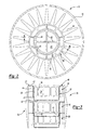
- Figure 1 is a partial cross-sectional perspective view of the present invention filter;
- Figure 2 is a top view of the filter shown in Figure 1;
- Figure 3 is a cross-sectional view of the filter shown in Figure 2 taken along lines 3-3;
- Figure 4 is a side perspective view of one of the discs of the center tube assembly shown in Figure 3; and
- Figure 5 is a side perspective view of a disc similar to that shown in Figure 4 with an extended outer portion.
-
- A
filter 10, shown in Figure 1, is typically used for filtering fluid such as in a lubrication system for an engine. Thefilter 10 includes a can orhousing 12 that may be constructed from one or more components secured to one another. For example, anut plate 14 may be secured to an outer cylindrical wall portion with aseam 18. An O-ring 16 is placed on thenut plate 14 to seal between thefilter 10 and a mounting adaptor (not shown). - The
filter 10 includes aninterior cavity 20 with afilter media 24 disposed within thecavity interior 20 to filter debris from the fluid so that clean fluid may be returned to the engine, such as for lubrication of engine components. Thefilter media 24 may be of a generally cylindrical shape and is typically pleated to forminner edges 25 that define acentral opening 27. Thefilter media 24 is typically retained between end caps, which are not shown for clarity. Thefilter media 24 has aninlet side 26 that receives dirty fluid and anoutlet side 28 where clean fluid exits thefilter media 24. Thenut plate 14 may include perforations 22 to permit dirty fluid to enter thefilter 10.Nut plate 14 may also include a threadedaperture 34 that is used to secure thefilter 10 to the mounting adaptor. The clean fluid exits thecentral opening 27 through the threadedaperture 34 and into the mounting adaptor. - It should be understood that the fluid flow may be reversed from that described above. Furthermore, the present invention center tube assembly may also be used with a cartridge type filter typically located within a suitable fixed housing. The filter media is retained between spaced apart end discs, such that the outer perimeter of the filter media is left exposed. Such a filter arrangement is well known in the art. Moreover, it is to be understood that the present invention center tube assembly, discussed below, may be used in any suitable filter configuration.
- A
center tube assembly 35 is disposed within thecentral opening 27 to provide structural integrity to thefilter 10 and permit fluid to pass through thecenter tube assembly 35 to the mounting adaptor. Thecenter tube assembly 35 is arranged proximate to thefilter media 24 to provide support to itsinner edges 25 to maintain the shape of thefilter media 24. Thecenter tube assembly 35 includesdiscs 36 that are stacked to a desired height. Referring to Figures 2-4, thecenter tube assembly 35 includes acentral portion 37 that may be any desirable shape. Thecentral portion 37 may include spaced apartvertical walls 38 defining openings 39. Thecentral portion 37 further includes abase 40 that is indented or recessed radially from thevertical walls 38 and is received by aninner wall 41 of theadjacent disc 36. Thebase 40 includesarms 42 extending between thevertical walls 38 to provide structural rigidity. Thearms 42 defineopenings 43 to permit the flow of fluid therethrough. Anouter portion 46 may extend radially outwardly from thecentral portion 37. Theouter portion 46 includes anannular wall 52 connected to thecentral portion 37 bylegs 50. Thelegs 50,annular wall 52, andcentral portion 37 defineopenings 53 that permit the flow of fluid therethrough. Fins 44 may be interconnected between thecentral portion 37 and theouter portion 46 to provide additional structural rigidity to thediscs 36. - The length of the
central portion 37 may be varied to providedifferent length discs 36 suitable for multiple filters. Moreover, a combination ofdiscs 36 having different lengthcentral portions 37 may be used to achieve a desired length of thecenter tube assembly 35. Similarly, different sizeouter portions 46 may also be used to provide various diameters of thecenter tube assembly 35, as best shown in Figure 5. - Preferably, the
center tube assembly 35 of the present invention is constructed from a plastic. Thecenter tube assembly 35 may be produced by a molding process. A dedicated mold may be used to produce a disc having a defined central portion length and outer portion diameter. Various molds may be used to provide sets of various sized discs that may be mixed or matched to provide a center tube assembly of a desired length and diameter. A mold may contain various inserts to provide different lengthcentral portions 37 and different diameters of theouter portion 46 so that only one mold may be needed, as will be appreciated of one of ordinary skilled in the art. Furthermore, thedisc 36 shown in Figure 5 may be trimmed to provide adisc 36 of the diameter shown in Figure 4 so that one mold may provide discs of different diameters. Alternatively, a more versatile mold may be used having inserts to vary the central portion length and outer portion diameter, as would be appreciated by one of ordinary skilled in the art. - The invention has been described in an illustrative manner, and it is to be understood that the terminology that has been used is intended to be in the nature of words of description rather than of limitation. Obviously, many modifications and variations of the present invention are possible in light of the above teachings. It is, therefore, to be understood that within the scope of the appended claims the invention may be practiced otherwise than as specifically described.
Claims (15)
- A filter (10) for a fluid system comprising:a housing (12) having an interior cavity (20);a filter media (24) disposed in said interior cavity defining a central opening (27); anda center tube assembly (35) disposed in said central opening and including first and second discs (36) stacked together with said first and second discs terminating in an outer portion (46) adjacent to said filter media.
- The filter according to claim 1, wherein said filter media is pleated forming inner edges proximate to said outer portion.
- The filter according to claim 1 or 2, wherein said filter media includes inlet and outlet sides (26, 28) with said center tube assembly disposed on said outlet side.
- The filter according to any preceding claim, wherein each of said first and second discs include a central portion (37) defining a length and said outer portion (46) extending radially outwardly from said central portion defining a diameter.
- The filter according to claim 4, wherein said outer portion (46) includes an annular wall (52) connected to said central portion by legs (50), and said legs, said annular wall, and said central portion defining openings.
- The filter according to claim 4 or 5, wherein said central portion of one of said first and second discs includes a vertical wall (38) with a base (40) indented from said vertical wall and received by an inner wall (41) of said central portion of another of said first and second discs.
- The filter according to claim 6, wherein said vertical wall includes a plurality of first openings (39), and said base includes a second opening (43).
- A center tube assembly (35) for an oil filter comprising:a first disc and a second disc (36) removably engaged with said first disc with each of said first and second discs including a central portion (37) defining a length and an outer portion (46) extending radially outwardly from said central portion, said central portion defining a diameter.
- The center tube according to claim 8, wherein said outer portion includes an annular wall (52) connected to said central portion by legs (50), and said legs, said annular wall, and said central portion defining openings (53).
- The center tube according to claim 8 or 9, wherein said central portion of one of said first and second discs includes a vertical wall (38) with a base (40) indented from said vertical wall and received by an inner wall (41) of said central portion of another of said first and second discs.
- The center tube according to claim 10, wherein said vertical wall includes a plurality of first openings (39), and said base includes a second opening (43).
- The center tube according to any of claims 8 to 11, wherein said first and second discs are plastic.
- A method of assembling a filter (10) comprising the steps of:a) providing a filter media (24) having a central opening (27);b) stacking a first disc (36) onto a second disc (36) forming a center tube assembly (35); andc) inserting the center tube assembly into the central opening.
- The method according to claim 13, wherein the first and second discs include a central portion (37) defining a length and an outer portion extending radially outwardly from the central portion, the central portion defining a diameter.
- The method according to claim 13 or 14, wherein the first and second discs together define a desired center tube assembly length and a desired center tube assembly diameter.
Applications Claiming Priority (2)
| Application Number | Priority Date | Filing Date | Title |
|---|---|---|---|
| US445498 | 2003-05-27 | ||
| US10/445,498 US6962256B2 (en) | 2003-05-27 | 2003-05-27 | Plastic molded center tube assembly |
Publications (1)
| Publication Number | Publication Date |
|---|---|
| EP1481715A1 true EP1481715A1 (en) | 2004-12-01 |
Family
ID=33131536
Family Applications (1)
| Application Number | Title | Priority Date | Filing Date |
|---|---|---|---|
| EP20040253067 Withdrawn EP1481715A1 (en) | 2003-05-27 | 2004-05-25 | Center tube for filters |
Country Status (7)
| Country | Link |
|---|---|
| US (2) | US6962256B2 (en) |
| EP (1) | EP1481715A1 (en) |
| JP (2) | JP4656860B2 (en) |
| CN (1) | CN1287883C (en) |
| AU (1) | AU2004202233A1 (en) |
| BR (1) | BRPI0401829A (en) |
| MX (1) | MXPA04005101A (en) |
Cited By (4)
| Publication number | Priority date | Publication date | Assignee | Title |
|---|---|---|---|---|
| DE202008010504U1 (en) * | 2008-08-07 | 2009-12-17 | Mann+Hummel Gmbh | Filter system for filtering fluids |
| ITBL20090005A1 (en) * | 2009-02-18 | 2010-08-19 | T I S P A Sa | DISTANCE RING OF PRISMATIC ELEMENTS FOR FILTRATION MEMBRANES. |
| DE102013012013A1 (en) | 2013-07-18 | 2015-01-22 | Mann + Hummel Gmbh | Support tube, filter element and filter system with a support tube and method and apparatus for producing the support tube |
| WO2015189774A1 (en) * | 2014-06-11 | 2015-12-17 | Boll & Kirch Filterbau Gmbh | Backflush filter and filter insert for the latter |
Families Citing this family (31)
| Publication number | Priority date | Publication date | Assignee | Title |
|---|---|---|---|---|
| JP2008531249A (en) * | 2005-02-22 | 2008-08-14 | ボールドウィン フィルターズ,インコーポレイティド | Filter device |
| US8057669B2 (en) | 2005-02-22 | 2011-11-15 | Baldwin Filters, Inc. | Filter element and filter assembly including locking mechanism |
| US20080251442A1 (en) * | 2005-09-28 | 2008-10-16 | Pall Corporation | Fluid Treatment Assemblies and Elements and Methods for Making Them |
| JP4597054B2 (en) * | 2006-01-05 | 2010-12-15 | 和興フィルタテクノロジー株式会社 | filter |
| JP4523924B2 (en) * | 2006-03-23 | 2010-08-11 | 株式会社ノリタケカンパニーリミテド | Ceramic straight tube hole cylindrical support and oxygen separation membrane |
| US20090057221A1 (en) * | 2007-08-28 | 2009-03-05 | Filter Resources, Inc. | Pleated Woven Wire Filter |
| AR070160A1 (en) * | 2008-01-14 | 2010-03-17 | Purolator Filters Na Llc | LOWER SUPPORT MADE OF A COMBINATION OF TWO RESILIENT PARTS AND RELIEF VALVE SEAL ELEMENT FOR FLUID FILTERS |
| AR070161A1 (en) * | 2008-01-14 | 2010-03-17 | Purolator Filters Na Llc | SINGLE PIECE VALVE COMBINING ANTI-DRAIN AND RELIEF RETENTION |
| TWI473643B (en) * | 2008-01-14 | 2015-02-21 | Mann & Hummel Purolator Filters Llc | Single piece resilient combination bottom support and relief valve end seal element for fluid filters |
| US9095795B2 (en) * | 2008-02-27 | 2015-08-04 | Mann+Hummel Purolator Filters Llc | Anti-drainback valve with position positive locking for spin-on oil and fuel filters |
| US20090211964A1 (en) * | 2008-02-27 | 2009-08-27 | Purolator Filters Na Llc | Corrugated-Ribbed Thread Plates for Oil/Fuel Spin-on Filters |
| US8815090B2 (en) * | 2008-06-16 | 2014-08-26 | Baldwin Filters, Inc. | Filter with water separation device |
| US8128819B2 (en) * | 2008-06-16 | 2012-03-06 | Baldwin Filters Inc. | Fluid filter, fluid filter assembly, and mounting method |
| US8241493B2 (en) | 2008-06-16 | 2012-08-14 | Baldwin Filters, Inc. | Filter with ejection mechanism |
| US7980396B2 (en) * | 2008-07-01 | 2011-07-19 | Purolator Filters Na Llc | Truss type high pressure center support for liquid filtration |
| US8808552B2 (en) * | 2010-12-16 | 2014-08-19 | Zenpure (Hangzhou) Co., Ltd. | Stackable filter cup apparatus and method |
| CN102489059B (en) * | 2011-12-08 | 2014-04-09 | 成都华西工业气体有限公司 | Self-cleaning filter |
| US8991619B2 (en) | 2012-03-26 | 2015-03-31 | Baldwin Filters, Inc. | Filter assembly with water evacuation and methods |
| KR101360110B1 (en) | 2012-04-17 | 2014-02-11 | 김현용 | Device for descaling scale of pipe |
| JP6339101B2 (en) | 2013-01-04 | 2018-06-06 | ボールドウィン・フィルターズ・インコーポレーテッドBaldwin Filters Inc | Filter element including three-part end cap and similar elements |
| CN105317503A (en) * | 2015-12-07 | 2016-02-10 | 邵良玉 | Filter element for automobile filter |
| CN105536545A (en) * | 2016-01-28 | 2016-05-04 | 诺克尔过滤(苏州)有限公司 | Top-in high-flow anti-pollution filtering machine |
| US10427078B2 (en) | 2016-07-15 | 2019-10-01 | Donaldson Company, Inc. | Filter element and support structure |
| CN107100694A (en) * | 2017-03-29 | 2017-08-29 | 索格菲(苏州)汽车部件有限公司 | The oil strainer of engine |
| KR102211420B1 (en) * | 2017-09-28 | 2021-02-03 | 주식회사 엘지화학 | Reverse Osmotic membrane filter module |
| MX2020005694A (en) | 2017-12-08 | 2020-08-20 | Cummins Filtration Ip Inc | Oval seal with stabilization contour. |
| US10918978B2 (en) | 2018-05-08 | 2021-02-16 | Cummins Filtration Ip, Inc. | Oval filter with exterior elliptical radial seal and internal support structure |
| USD884866S1 (en) | 2018-05-08 | 2020-05-19 | Cummins Filtration Ip, Inc. | Filter element |
| WO2019219654A1 (en) * | 2018-05-18 | 2019-11-21 | Mann+Hummel Gmbh | Support tube for a filter element, filter element comprising a support tube, and method for producing such a filter element |
| US11679347B2 (en) * | 2018-09-17 | 2023-06-20 | McFarlen Engineering Ltd. | Filter support element and method of using same |
| USD969289S1 (en) | 2020-03-05 | 2022-11-08 | Cummins Filtration Inc. | Filter element |
Citations (7)
| Publication number | Priority date | Publication date | Assignee | Title |
|---|---|---|---|---|
| DE1902534U (en) * | 1964-04-30 | 1964-10-22 | Faudi Feinbau G M B H | FILTER CANDLE FOR SCREW-ON FILTER. |
| GB1441269A (en) * | 1973-04-26 | 1976-06-30 | Stockdale Eng Ltd | Filter units |
| US4105562A (en) * | 1976-05-06 | 1978-08-08 | Textron Inc. | Filtering apparatus with modular filter elements |
| DE2811943A1 (en) * | 1978-03-18 | 1979-09-27 | Roland Hagemann | Aquarium filter with modular construction - has water deflection chamber with several connection holes for filter bodies |
| US5601711A (en) * | 1994-10-31 | 1997-02-11 | Gelman Sciences Inc. | Selective separation filter device |
| EP0769317A1 (en) * | 1995-10-20 | 1997-04-23 | Siebec S.A. | Cartridge filter with a rigid tubular core |
| US6511101B1 (en) * | 1996-08-02 | 2003-01-28 | Filterwerk Mann & Hummel Gmbh | Snap-on central support tube for a filter element |
Family Cites Families (8)
| Publication number | Priority date | Publication date | Assignee | Title |
|---|---|---|---|---|
| DE1902534A1 (en) | 1969-01-18 | 1970-08-13 | Bauknecht Gmbh G | Cutter drive device |
| JPH0644951Y2 (en) * | 1989-10-23 | 1994-11-16 | 株式会社アイチコーポレーション | Bucket device for aerial work vehicles |
| FR2726483B1 (en) * | 1994-11-09 | 1997-01-24 | Siebec Sa | FILTER CARTRIDGE WITH MOBILE CROWN HOLDING |
| JP3016414B2 (en) * | 1995-04-25 | 2000-03-06 | 和興産業株式会社 | Filter element |
| US5906737A (en) * | 1997-05-01 | 1999-05-25 | Hoeppner; Michael A. | Filter core system |
| JP4478253B2 (en) * | 1999-07-30 | 2010-06-09 | 株式会社泰光 | Tubular filter element |
| DE29918105U1 (en) * | 1999-10-14 | 1999-12-23 | Mann & Hummel Filter | Filter cartridge with center tube |
| US6783833B2 (en) * | 2002-07-15 | 2004-08-31 | Itw Fleetwood-Signode | Protector for sheet metal coils |
-
2003
- 2003-05-27 US US10/445,498 patent/US6962256B2/en not_active Expired - Fee Related
-
2004
- 2004-05-24 AU AU2004202233A patent/AU2004202233A1/en not_active Abandoned
- 2004-05-25 EP EP20040253067 patent/EP1481715A1/en not_active Withdrawn
- 2004-05-25 BR BR0401829-0A patent/BRPI0401829A/en not_active IP Right Cessation
- 2004-05-26 JP JP2004155852A patent/JP4656860B2/en not_active Expired - Fee Related
- 2004-05-27 MX MXPA04005101A patent/MXPA04005101A/en active IP Right Grant
- 2004-05-27 CN CNB2004100429155A patent/CN1287883C/en not_active Expired - Fee Related
-
2005
- 2005-09-01 US US11/217,558 patent/US7168572B2/en not_active Expired - Fee Related
-
2008
- 2008-12-16 JP JP2008319361A patent/JP2009148755A/en active Pending
Patent Citations (7)
| Publication number | Priority date | Publication date | Assignee | Title |
|---|---|---|---|---|
| DE1902534U (en) * | 1964-04-30 | 1964-10-22 | Faudi Feinbau G M B H | FILTER CANDLE FOR SCREW-ON FILTER. |
| GB1441269A (en) * | 1973-04-26 | 1976-06-30 | Stockdale Eng Ltd | Filter units |
| US4105562A (en) * | 1976-05-06 | 1978-08-08 | Textron Inc. | Filtering apparatus with modular filter elements |
| DE2811943A1 (en) * | 1978-03-18 | 1979-09-27 | Roland Hagemann | Aquarium filter with modular construction - has water deflection chamber with several connection holes for filter bodies |
| US5601711A (en) * | 1994-10-31 | 1997-02-11 | Gelman Sciences Inc. | Selective separation filter device |
| EP0769317A1 (en) * | 1995-10-20 | 1997-04-23 | Siebec S.A. | Cartridge filter with a rigid tubular core |
| US6511101B1 (en) * | 1996-08-02 | 2003-01-28 | Filterwerk Mann & Hummel Gmbh | Snap-on central support tube for a filter element |
Cited By (7)
| Publication number | Priority date | Publication date | Assignee | Title |
|---|---|---|---|---|
| DE202008010504U1 (en) * | 2008-08-07 | 2009-12-17 | Mann+Hummel Gmbh | Filter system for filtering fluids |
| ITBL20090005A1 (en) * | 2009-02-18 | 2010-08-19 | T I S P A Sa | DISTANCE RING OF PRISMATIC ELEMENTS FOR FILTRATION MEMBRANES. |
| DE102013012013A1 (en) | 2013-07-18 | 2015-01-22 | Mann + Hummel Gmbh | Support tube, filter element and filter system with a support tube and method and apparatus for producing the support tube |
| WO2015007421A1 (en) * | 2013-07-18 | 2015-01-22 | Mann+Hummel Gmbh | Support tube, filter element and filter system having a support tube, and method and device for producing the support tube |
| CN105378260A (en) * | 2013-07-18 | 2016-03-02 | 曼·胡默尔有限公司 | Support tube, filter element and filter system having a support tube, and method and device for producing the support tube |
| CN105378260B (en) * | 2013-07-18 | 2018-05-15 | 曼·胡默尔有限公司 | Support tube, filter element and the filtration system with support tube and the method and apparatus for process support pipe |
| WO2015189774A1 (en) * | 2014-06-11 | 2015-12-17 | Boll & Kirch Filterbau Gmbh | Backflush filter and filter insert for the latter |
Also Published As
| Publication number | Publication date |
|---|---|
| US20040238437A1 (en) | 2004-12-02 |
| JP2005040785A (en) | 2005-02-17 |
| AU2004202233A1 (en) | 2004-12-16 |
| US6962256B2 (en) | 2005-11-08 |
| JP2009148755A (en) | 2009-07-09 |
| JP4656860B2 (en) | 2011-03-23 |
| CN1287883C (en) | 2006-12-06 |
| CN1572352A (en) | 2005-02-02 |
| US20060016745A1 (en) | 2006-01-26 |
| MXPA04005101A (en) | 2005-07-01 |
| BRPI0401829A (en) | 2005-01-18 |
| US7168572B2 (en) | 2007-01-30 |
Similar Documents
| Publication | Publication Date | Title |
|---|---|---|
| EP1481715A1 (en) | Center tube for filters | |
| US7108139B2 (en) | Plastic extruded center tube profile and method of manufacture | |
| RU2668911C2 (en) | Filter cartridge arrangements and assemblies; preferred features; methods of assembly and use | |
| EP2151268B1 (en) | Fluid filtration apparatus and method | |
| US6571962B2 (en) | Cartridge filter element with housing seal retainer | |
| US6740234B1 (en) | Key track system | |
| US7837754B2 (en) | Multi-element filter arrangement and methods | |
| CA1311427C (en) | Integrated separator for solid and gaseous contaminants in a fluid | |
| US6085915A (en) | Back-washable spin-on oil filter | |
| US20090008320A1 (en) | Fluid Filter and Methods | |
| US20120223001A1 (en) | Filter and center tube with helical fin | |
| US7635429B2 (en) | Fluid filter element | |
| CA2252712A1 (en) | Inline filter apparatus | |
| CN114748941A (en) | Compressor system separator tank baffle and separation device for compressor system | |
| AU627392B2 (en) | Oil filter | |
| US11298640B2 (en) | Expandable threaded adaptor for threadless shell | |
| EP0342308B1 (en) | Integrated separator for solid and gaseous contaminants in a fluid | |
| US20040007541A1 (en) | Integrated liquid and gas distribution device for underdrain block laterals | |
| US20100044298A1 (en) | Centertube for a combination full flow and bypass filter apparatus | |
| EP0858823B1 (en) | Support structure for holding filter medium | |
| JP2004016857A (en) | Filtration arrangement, filter element support structure therefor and intermediate support plate for filter element | |
| CN116829239A (en) | End cap and pleat guide for filtration | |
| CA2526200A1 (en) | Filter for liquids, especially the transmission oil in automatic transmissions of motor vehicles |
Legal Events
| Date | Code | Title | Description |
|---|---|---|---|
| PUAI | Public reference made under article 153(3) epc to a published international application that has entered the european phase |
Free format text: ORIGINAL CODE: 0009012 |
|
| AK | Designated contracting states |
Kind code of ref document: A1 Designated state(s): AT BE BG CH CY CZ DE DK EE ES FI FR GB GR HU IE IT LI LU MC NL PL PT RO SE SI SK TR |
|
| AX | Request for extension of the european patent |
Extension state: AL HR LT LV MK |
|
| 17P | Request for examination filed |
Effective date: 20050509 |
|
| AKX | Designation fees paid |
Designated state(s): DE ES FR GB IT |
|
| RAP1 | Party data changed (applicant data changed or rights of an application transferred) |
Owner name: PUROLATOR FILTERS NA LLC |
|
| 17Q | First examination report despatched |
Effective date: 20070808 |
|
| STAA | Information on the status of an ep patent application or granted ep patent |
Free format text: STATUS: THE APPLICATION IS DEEMED TO BE WITHDRAWN |
|
| 18D | Application deemed to be withdrawn |
Effective date: 20090505 |