EP1480796B1 - Veneer slicer - Google Patents
Veneer slicer Download PDFInfo
- Publication number
- EP1480796B1 EP1480796B1 EP03737571A EP03737571A EP1480796B1 EP 1480796 B1 EP1480796 B1 EP 1480796B1 EP 03737571 A EP03737571 A EP 03737571A EP 03737571 A EP03737571 A EP 03737571A EP 1480796 B1 EP1480796 B1 EP 1480796B1
- Authority
- EP
- European Patent Office
- Prior art keywords
- flitch
- providing
- arm
- slide
- guide
- Prior art date
- Legal status (The legal status is an assumption and is not a legal conclusion. Google has not performed a legal analysis and makes no representation as to the accuracy of the status listed.)
- Expired - Lifetime
Links
Images





Classifications
-
- B—PERFORMING OPERATIONS; TRANSPORTING
- B27—WORKING OR PRESERVING WOOD OR SIMILAR MATERIAL; NAILING OR STAPLING MACHINES IN GENERAL
- B27L—REMOVING BARK OR VESTIGES OF BRANCHES; SPLITTING WOOD; MANUFACTURE OF VENEER, WOODEN STICKS, WOOD SHAVINGS, WOOD FIBRES OR WOOD POWDER
- B27L5/00—Manufacture of veneer ; Preparatory processing therefor
- B27L5/06—Cutting strips from a stationarily- held trunk or piece by a rocking knife carrier, or from rocking trunk or piece by a stationarily-held knife carrier; Veneer- cutting machines
-
- B—PERFORMING OPERATIONS; TRANSPORTING
- B23—MACHINE TOOLS; METAL-WORKING NOT OTHERWISE PROVIDED FOR
- B23Q—DETAILS, COMPONENTS, OR ACCESSORIES FOR MACHINE TOOLS, e.g. ARRANGEMENTS FOR COPYING OR CONTROLLING; MACHINE TOOLS IN GENERAL CHARACTERISED BY THE CONSTRUCTION OF PARTICULAR DETAILS OR COMPONENTS; COMBINATIONS OR ASSOCIATIONS OF METAL-WORKING MACHINES, NOT DIRECTED TO A PARTICULAR RESULT
- B23Q1/00—Members which are comprised in the general build-up of a form of machine, particularly relatively large fixed members
- B23Q1/25—Movable or adjustable work or tool supports
- B23Q1/44—Movable or adjustable work or tool supports using particular mechanisms
- B23Q1/50—Movable or adjustable work or tool supports using particular mechanisms with rotating pairs only, the rotating pairs being the first two elements of the mechanism
- B23Q1/54—Movable or adjustable work or tool supports using particular mechanisms with rotating pairs only, the rotating pairs being the first two elements of the mechanism two rotating pairs only
- B23Q1/5468—Movable or adjustable work or tool supports using particular mechanisms with rotating pairs only, the rotating pairs being the first two elements of the mechanism two rotating pairs only a single rotating pair followed parallelly by a single rotating pair
- B23Q1/5481—Movable or adjustable work or tool supports using particular mechanisms with rotating pairs only, the rotating pairs being the first two elements of the mechanism two rotating pairs only a single rotating pair followed parallelly by a single rotating pair followed parallelly by a single rotating pair
-
- B—PERFORMING OPERATIONS; TRANSPORTING
- B23—MACHINE TOOLS; METAL-WORKING NOT OTHERWISE PROVIDED FOR
- B23Q—DETAILS, COMPONENTS, OR ACCESSORIES FOR MACHINE TOOLS, e.g. ARRANGEMENTS FOR COPYING OR CONTROLLING; MACHINE TOOLS IN GENERAL CHARACTERISED BY THE CONSTRUCTION OF PARTICULAR DETAILS OR COMPONENTS; COMBINATIONS OR ASSOCIATIONS OF METAL-WORKING MACHINES, NOT DIRECTED TO A PARTICULAR RESULT
- B23Q5/00—Driving or feeding mechanisms; Control arrangements therefor
- B23Q5/02—Driving main working members
- B23Q5/027—Driving main working members reciprocating members
Definitions
- This invention is disclosed in the context of machinery for the manufacture of wood veneers.
- a veneer slicer 23 includes a flitch table 20, for example, a vacuum-type or hydraulic dog-type flitch table, on which is mounted a flitch 22 which is to be sliced into veneer.
- the flitch 22 is sliced by moving it in contact with the cutting edge of a knife 24 in a cutting stroke.
- the knife 24 is mounted on, for example, a carriage 25 of the type illustrated and described in U. S. Patent 5,979,524 , which supports the knife 24 and a pressure bar.
- the flitch 22 and knife 24 are relatively retracted away from contact with each other, and returned to their relative positions for execution of the next cutting stroke. These cutting and return strokes are executed at a rate of, for example, 90 times a minute as the flitch 22 is converted to sheets of veneer.
- a typical flitch 22 includes grain that generally runs relatively at least somewhat toward the knife 24 during the first half of the cutting stroke and generally relatively somewhat away from the knife 24 during the second half of the cutting stroke, owing to the way the wood of the typical flitch 22 has grown.
- the grain of the veneer sliced from the flitch 22 tends to be "rubbed up” and rougher on the half of each sheet of veneer sliced from a first half cut generally against the grain, for example, the upper half 26, of a typical flitch 22, and smoother on the half of each sheet of veneer sliced from a second half cut generally with the grain, for example, the lower half 28 of a typical flitch 22. That is, as the knife 24 proceeds "into" the flitch 22, the grain tends to be more rubbed up. As the knife 24 proceeds "out of" the flitch 22, the grain tends to be less rubbed up.
- This difference in surface smoothness can be visually detected by visual inspection of the sheets of veneer, and/or otherwise physically detected, for example, felt by rubbing the sheets of veneer as they come off the veneer slicer to the offbearers' station 30 to be, for example, stacked for further processing, for example, drying.
- the present invention alleviates some of this difference in surface smoothness across the surface of the sliced sheet of veneer by slowing the relative motion of the knife 24 and flitch 22 during one part, for example, the first part, of the cutting stroke and speeding up the relative motion of the knife 24 and flitch 22 during another part, for example, the second part, of the cutting stroke.
- This is done in the embodiment illustrated in Figs. 1a-e and 2-4 by mounting the flitch table 20 on (a) pivot arm(s) 32 to impart a rocking motion to the flitch table 20 rather than the prior art linear reciprocating motion.
- the flitch table 20 is rocked in such a way that each point 34 ( Fig.
- the arc 36's length is about a quarter of a circle.
- the radius of the circle is the effective radius (radii) of (a) flitch table motion arm(s) 32 by which the flitch table 20 is supported on the veneer slicer 23.
- each flitch table motion arm 32 is pivotally mounted at one end by a pin 38 to a support 40 on which the flitch table 20 is mounted.
- Each flitch table motion arm 32 is mounted at its other end to a flitch table turning shaft 42 which is pivotally supported in a stationary support framework 44.
- the stationary support framework 44 also rotatably supports a drive shaft 46 which is appropriately counterweighted.
- Drive shaft 46 includes a crank arm 48, the end of which remote from drive shaft 46 is pivotally coupled to one end of a connecting rod 50.
- the other end of connecting rod 50 is coupled to a drive lever 52 stationarily connected to one of the flitch table motion arms 32.
- the rocking motion of the flitch table 20 is thus obtained by rotation of drive shaft 46.
- Rotation of drive shaft 46 is achieved by a prime mover 47 (Fig. la), for example, an electric motor, typically via a speed reducing transmission including (a) pulley(s) 49 mounted on the output shaft of the prime mover 47, belt(s) 51 trained about the pulley(s) 49 on the output shaft of the prime mover 47 and about (an) input pulley(s) 53 of a clutch-brake combination 55, for example, an air clutch, a clutch-brake combination output shaft 57, (a) drive pulley(s) 59, (a) chain(s) 68, and (a) driven pulley(s) 70 provided on drive shaft 46.
- a prime mover 47 for example, an electric motor
- a speed reducing transmission including (a) pulley(s) 49 mounted on the output shaft of the prime mover 47, belt(s) 51 trained about the pulley(s) 49 on the output shaft of the prime mover 47 and about (an) input pulley(s) 53 of a clutch-
- (an) arcuate track(s) 80 and arcuate slide(s) 82 for engaging the arcuate track(s) 80 can be added to the support apparatus 84 for the flitch table 20.
- the track(s) 80 and track 80-following grooves in the slide(s) 82 would have the same radii of curvature as the effective radius (radii) of flitch table motion arm(s) 32 by which the flitch table 20 is supported on the veneer slicer 23.
- the slide(s) 82 would be pivotally mounted to the table 20.
- the slide(s) 82 can, for example, be (a) solid bearing slide(s), or can be provided with ball- or roller-bearings, including circulating ball- or roller-bearings of the type described in, for example, U. S. Patent 6,102,090 .
- FIG. 6-7 another method for achieving the slower-to-faster slicing motion which permits the execution of even more complex motions is to mount the flitch table support 86 from the supporting framework 88 using conventional means, such as for example, (a) linear track(s) 92 and (a) linear solid bearing- or ball- or roller-bearing slide(s) 90, including circulating ball- or roller-bearings of the type described in, for example, U. S. Patent 6,102,090 .
- conventional means such as for example, (a) linear track(s) 92 and (a) linear solid bearing- or ball- or roller-bearing slide(s) 90, including circulating ball- or roller-bearings of the type described in, for example, U. S. Patent 6,102,090 .
- the flitch table 20 is then mounted from the flitch table support 86 by, for example, (a) horizontal or generally horizontal linear track(s) 100 mounted on one of the support 86 and table 20 and bearings(s) 102 of the type described in, for example, U. S. Patent 6,102,090 mounted on the other of the support 86 and table 20.
- Some drive means 104 such as, for example, (a) reversible electric or hydraulic motor(s), is provided between the flitch table 20 and its support 86.
- the flitch table 20 can simultaneously be driven horizontally at (a) rate(s) by supplying current to the electric motor(s) or supplying and/or removing hydraulic fluid to and/or from the hydraulic motor(s) 104 according to a suitable algorithm. In this way, any of a number of desired motions of the flitch 22 relative to the knife 24 can be achieved.
Landscapes
- Engineering & Computer Science (AREA)
- Mechanical Engineering (AREA)
- Life Sciences & Earth Sciences (AREA)
- Manufacturing & Machinery (AREA)
- Wood Science & Technology (AREA)
- Forests & Forestry (AREA)
- Manufacture Of Wood Veneers (AREA)
- Chemical And Physical Treatments For Wood And The Like (AREA)
- Treatment Of Fiber Materials (AREA)
- Acyclic And Carbocyclic Compounds In Medicinal Compositions (AREA)
- Veneer Processing And Manufacture Of Plywood (AREA)
Abstract
Description
- This invention is disclosed in the context of machinery for the manufacture of wood veneers.
- There are several known types of machines for the production of wood veneers. There are, for example, the machines illustrated and described in
U. S. Patents: 2,576,520 ;2,676,627 ;3,441,069 ;3,654,973 ;3,680,612 ;3,750,725 ;4,063,578 ;4,068,693 ;4,069,850 ;4,083,391 ;4,089,354 ;4,102,372 ;4,137,957 ;4,287,462 ;4,392,519 ;4,503,740 ;4,503,896 ;4,587,616 ;4,601,317 ;4,753,278 ;4,791,970 ;4,831,747 ;4,893,663 ;5,067,534 ;5,101,874 ;5,143,129 ;5,381,841 ;5,383,504 ;5,385,185 ;5,452,220 ;5,490,548 ;5,511,598 ;5,562,137 ;5,590,700 ;5,680,887 ;5,979,524 ; and,6,102,090 ; Canadian Patent1,204,985 ; German Patent Specifications:2,501,936 ;2,523,481 ;2,523,482 ;3,915,516 ;3,928,941 ; and, Italian Patent Specifications:1,084,683 1,126,371 - The invention is defined in the independent claims. Preferred embodiments thereof are defined in the dependent claims.
- The invention may best be understood by referring to the following detailed description of an illustrative embodiment of the invention, and the accompanying drawings. In the drawings:
-
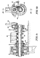
Fig. 1a illustrates a partial sectional top plan view of a system constructed according to the present invention; -
Fig. 1b illustrates a fragmentary elevational view of a detail of the system illustrated inFig. 1a ; -
Fig. 1c illustrates a sectional view of the detail illustrated inFig. 1b , taken generally alongsection lines 1c-1c ofFig. 1b ; -
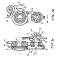
Fig. 1d illustrates a fragmentary elevational view of a detail of the system illustrated inFig. 1a ; -
Fig. 1e illustrates a sectional view of the detail illustrated inFig. 1d , taken generally alongsection lines 1e-1e ofFig. 1d ; -
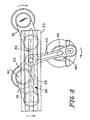
Figs. 2-4 illustrate elevational views of certain components of the system illustrated inFig. 1 , in various orientations the illustrated components assume during each cycle of operation of the system illustrated inFig. 1 ; -
Fig. 5 illustrates an elevational view of certain components according to the invention; and, -
Figs. 6-7 illustrate partly broken away elevational views of certain components of another system not comprised in the invention. - Referring now to the drawings, a
veneer slicer 23 includes a flitch table 20, for example, a vacuum-type or hydraulic dog-type flitch table, on which is mounted aflitch 22 which is to be sliced into veneer. Theflitch 22 is sliced by moving it in contact with the cutting edge of aknife 24 in a cutting stroke. Theknife 24 is mounted on, for example, acarriage 25 of the type illustrated and described inU. S. Patent 5,979,524 , which supports theknife 24 and a pressure bar. After completion of the cutting stroke, theflitch 22 andknife 24 are relatively retracted away from contact with each other, and returned to their relative positions for execution of the next cutting stroke. These cutting and return strokes are executed at a rate of, for example, 90 times a minute as theflitch 22 is converted to sheets of veneer. - In the past, the relative movement between the
flitch 22 andknife 24 in veneer slicers of this type has always been linear. The present invention recognizes that atypical flitch 22 includes grain that generally runs relatively at least somewhat toward theknife 24 during the first half of the cutting stroke and generally relatively somewhat away from theknife 24 during the second half of the cutting stroke, owing to the way the wood of thetypical flitch 22 has grown. As a result of this, the grain of the veneer sliced from theflitch 22 tends to be "rubbed up" and rougher on the half of each sheet of veneer sliced from a first half cut generally against the grain, for example, theupper half 26, of atypical flitch 22, and smoother on the half of each sheet of veneer sliced from a second half cut generally with the grain, for example, thelower half 28 of atypical flitch 22. That is, as theknife 24 proceeds "into" theflitch 22, the grain tends to be more rubbed up. As theknife 24 proceeds "out of" theflitch 22, the grain tends to be less rubbed up. This difference in surface smoothness can be visually detected by visual inspection of the sheets of veneer, and/or otherwise physically detected, for example, felt by rubbing the sheets of veneer as they come off the veneer slicer to the offbearers'station 30 to be, for example, stacked for further processing, for example, drying. - The present invention alleviates some of this difference in surface smoothness across the surface of the sliced sheet of veneer by slowing the relative motion of the
knife 24 andflitch 22 during one part, for example, the first part, of the cutting stroke and speeding up the relative motion of theknife 24 andflitch 22 during another part, for example, the second part, of the cutting stroke. This is done in the embodiment illustrated inFigs. 1a-e and2-4 by mounting the flitch table 20 on (a) pivot arm(s) 32 to impart a rocking motion to the flitch table 20 rather than the prior art linear reciprocating motion. The flitch table 20 is rocked in such a way that each point 34 (Fig. 2 ) on the flitch table 20 andflitch 22 supported on the flitch table 20 moves along anarc 36 of a circle. In the illustrated embodiment, thearc 36's length is about a quarter of a circle. The radius of the circle is the effective radius (radii) of (a) flitch table motion arm(s) 32 by which the flitch table 20 is supported on theveneer slicer 23. Thus, during thefirst portion 26 of the slicing of a sheet of veneer from atypical flitch 22, when the cut is more against the grain of theflitch 22, the relative movement of theknife 24 andflitch 22 is more horizontal and the progress of theknife 24 through theflitch 22 thus slower. The relative movement of theknife 24 andflitch 22 becomes more vertical and the progress of theknife 24 through theflitch 22 faster as the cutting of a slice of veneer from thetypical flitch 22 progresses, for example, during the cutting ofportion 28. - Referring now particularly to
Figs. 2-4 , to achieve this motion of the flitch table 20, each flitchtable motion arm 32 is pivotally mounted at one end by apin 38 to asupport 40 on which the flitch table 20 is mounted. Each flitchtable motion arm 32 is mounted at its other end to a flitchtable turning shaft 42 which is pivotally supported in astationary support framework 44. Thestationary support framework 44 also rotatably supports adrive shaft 46 which is appropriately counterweighted.Drive shaft 46 includes acrank arm 48, the end of which remote fromdrive shaft 46 is pivotally coupled to one end of a connectingrod 50. The other end of connectingrod 50 is coupled to adrive lever 52 stationarily connected to one of the flitchtable motion arms 32. The rocking motion of the flitch table 20 is thus obtained by rotation ofdrive shaft 46. - Rotation of
drive shaft 46 is achieved by a prime mover 47 (Fig. la), for example, an electric motor, typically via a speed reducing transmission including (a) pulley(s) 49 mounted on the output shaft of theprime mover 47, belt(s) 51 trained about the pulley(s) 49 on the output shaft of theprime mover 47 and about (an) input pulley(s) 53 of a clutch-brake combination 55, for example, an air clutch, a clutch-brakecombination output shaft 57, (a) drive pulley(s) 59, (a) chain(s) 68, and (a) driven pulley(s) 70 provided ondrive shaft 46. - Referring now to
Fig. 5 , because the flitch table 20 moves in anarc 36 and additional support of the flitch table 20 is necessary, (an) arcuate track(s) 80 and arcuate slide(s) 82 for engaging the arcuate track(s) 80 can be added to thesupport apparatus 84 for the flitch table 20. The track(s) 80 and track 80-following grooves in the slide(s) 82 would have the same radii of curvature as the effective radius (radii) of flitch table motion arm(s) 32 by which the flitch table 20 is supported on theveneer slicer 23. The slide(s) 82 would be pivotally mounted to the table 20. The slide(s) 82 can, for example, be (a) solid bearing slide(s), or can be provided with ball- or roller-bearings, including circulating ball- or roller-bearings of the type described in, for example,U. S. Patent 6,102,090 . - Referring now to
Figs. 6-7 , another method for achieving the slower-to-faster slicing motion which permits the execution of even more complex motions is to mount theflitch table support 86 from the supportingframework 88 using conventional means, such as for example, (a) linear track(s) 92 and (a) linear solid bearing- or ball- or roller-bearing slide(s) 90, including circulating ball- or roller-bearings of the type described in, for example,U. S. Patent 6,102,090 . The flitch table 20 is then mounted from theflitch table support 86 by, for example, (a) horizontal or generally horizontal linear track(s) 100 mounted on one of thesupport 86 and table 20 and bearings(s) 102 of the type described in, for example,U. S. Patent 6,102,090 mounted on the other of thesupport 86 and table 20. Some drive means 104, such as, for example, (a) reversible electric or hydraulic motor(s), is provided between the flitch table 20 and itssupport 86. Then, as theflitch table support 86 is moved linearly generally vertically, or at an acute angle to vertical, the flitch table 20 can simultaneously be driven horizontally at (a) rate(s) by supplying current to the electric motor(s) or supplying and/or removing hydraulic fluid to and/or from the hydraulic motor(s) 104 according to a suitable algorithm. In this way, any of a number of desired motions of theflitch 22 relative to theknife 24 can be achieved.
Claims (14)
- A veneer slicer (23) including a knife (24), a flitch table (20) for supporting a flitch (22), a bell crank (52, 32) having a first arm (52) and a second arm (32), the second arm (32) having an effective radius, a prime mover (47) driving a crankshaft (46), a connecting rod (50) coupling the first arm (52) to the crankshaft (46), the second arm (32) coupled to the flitch table (20), a guide (80) and a follower (82) for following the guide (80), one of the guide (80) and follower (82) being movable with the flitch table (20) and the other of the guide (80) and follower (82) being stationary, the guide (80) and follower (82) including an arcuate track (80) and a slide (82) for following the track (80), the track (80) having a radius of curvature equal to the effective radius of the second arm (32), the bell crank (52, 32), connecting rod (50), crankshaft (46), guide (80) and follower (82) reciprocating the flitch table (20) such that the flitch (22) is intermittently drawn across the knife (24) to slice veneer from the flitch (22).
- The apparatus of claim 1 wherein the length of the arcuate track (80) is about a quarter of a circle having a radius equal to the effective radius of the second arm (32).
- The apparatus of claim 1 wherein the slide (82) includes a solid bearing slide.
- The apparatus of claim 1 wherein the slide (82) includes ball bearings.
- The apparatus of claim 4 wherein the ball bearings are circulating type ball bearings.
- The apparatus of claim 1 wherein the slide (82) includes roller bearings.
- The apparatus of claim 6 wherein the roller bearings are circulating type roller bearings.
- A method of converting a flitch (22) into sheets of veneer, the method including providing a bell crank (52, 32) having a first arm (52) and a second arm (32) having an effective radius, providing a prime mover (47) driving a crankshaft (46), coupling the first arm (52) to the crankshaft (46), and coupling the second arm (32) to a flitch table (20) against which the flitch (22) is mounted, rotation of the crankshaft (46) with the flitch (22) in contact with a knife (24) causing sheets of veneer to be cut from the flitch (22), providing a guide (80) and a follower (82) for following the guide (80), one of the guide (80) and follower (82) being movable with the flitch table (20) and the other of the guide (80) and follower (82) being stationary, providing a guide (80) and a follower (82) for following the guide (80) including providing an arcuate track (80) and a slide (82) for following the track (80), the track (80) having the same radius of curvature as the effective radius of the second arm (32).
- The method of claim 8 wherein providing an arcuate track (80) includes providing an arcuate track (80) having a length of about a quarter of a circle having a radius equal to the effective radius of the second arm (32).
- The method of claim 8 wherein providing a slide (82) includes providing a solid bearing slide.
- The method of claim 8 wherein providing a slide (82) includes providing a ball bearing slide.
- The method of claim 11 wherein providing a ball bearing slide (82) includes providing a circulating-type ball bearing slide.
- The method of claim 8 wherein providing a slide (82) includes providing a roller bearing slide.
- The method of claim 13 wherein providing a roller bearing slide (82) includes providing a circulating-type roller bearing slide.
Applications Claiming Priority (3)
| Application Number | Priority Date | Filing Date | Title |
|---|---|---|---|
| US35423602P | 2002-02-04 | 2002-02-04 | |
| US354236P | 2002-02-04 | ||
| PCT/US2003/002870 WO2003066295A2 (en) | 2002-02-04 | 2003-01-31 | Veneer slicer |
Publications (3)
| Publication Number | Publication Date |
|---|---|
| EP1480796A2 EP1480796A2 (en) | 2004-12-01 |
| EP1480796A4 EP1480796A4 (en) | 2007-03-21 |
| EP1480796B1 true EP1480796B1 (en) | 2008-06-11 |
Family
ID=27734336
Family Applications (1)
| Application Number | Title | Priority Date | Filing Date |
|---|---|---|---|
| EP03737571A Expired - Lifetime EP1480796B1 (en) | 2002-02-04 | 2003-01-31 | Veneer slicer |
Country Status (9)
| Country | Link |
|---|---|
| US (4) | US7458404B2 (en) |
| EP (1) | EP1480796B1 (en) |
| JP (3) | JP4113130B2 (en) |
| AT (1) | ATE398006T1 (en) |
| AU (1) | AU2003210756A1 (en) |
| BR (1) | BR0307362A (en) |
| CA (2) | CA2646684C (en) |
| DE (1) | DE60321545D1 (en) |
| WO (1) | WO2003066295A2 (en) |
Cited By (1)
| Publication number | Priority date | Publication date | Assignee | Title |
|---|---|---|---|---|
| US7918253B2 (en) | 2002-02-04 | 2011-04-05 | Padana Ag | Veneer slicer |
Families Citing this family (1)
| Publication number | Priority date | Publication date | Assignee | Title |
|---|---|---|---|---|
| CN102229154B (en) * | 2011-06-24 | 2013-04-10 | 丁占科 | Longitudinal veneer slicer |
Family Cites Families (54)
| Publication number | Priority date | Publication date | Assignee | Title |
|---|---|---|---|---|
| US674562A (en) * | 1900-03-05 | 1901-05-21 | Friedrich Kraus | Veneer-cutter. |
| US793306A (en) * | 1904-04-04 | 1905-06-27 | Louis Koss | Veneer-slicer. |
| US2303213A (en) * | 1940-12-23 | 1942-11-24 | Capital Machine Company | Knife rocking mechanism for veneer cutting machines |
| US2592782A (en) * | 1947-01-10 | 1952-04-15 | George E Zweifel & Company | Hydraulic slicer |
| US2676627A (en) * | 1948-10-18 | 1954-04-27 | Johnson City Foundry & Machine | Veneer slicer |
| US2576520A (en) * | 1948-11-04 | 1951-11-27 | Capital Machine Company | Hydraulic control of veneer slicing machines |
| GB1130510A (en) * | 1965-03-08 | 1968-10-16 | Capital Machine Co | A method of obtaining water-stain-free veneer |
| US3654973A (en) * | 1970-10-19 | 1972-04-11 | Capital Machine Co | Hydraulically controlled pressure cap |
| FR2114320A5 (en) * | 1970-11-13 | 1972-06-30 | Cremona Angelo | |
| US3680612A (en) * | 1971-03-17 | 1972-08-01 | Capital Machine Co | Extension dog system for veneer slicer |
| US3905408A (en) * | 1974-03-29 | 1975-09-16 | Capital Machine Co | Vacuum flitch table for veneer slicer |
| IT1025462B (en) | 1974-11-06 | 1978-08-10 | Cremona Angelo | EQUIPMENT SUITABLE FOR THE AUTOMATIC LOADING OF WET SHEETS INTO A DRYER WITH BELTS OT A SHEETS AS WELL AS THE UNLOADING AND STACKING OF THE DRY SHEETS FROM IT |
| IT1025496B (en) | 1974-11-07 | 1978-08-10 | Cremona Angelo | AUTOMATIC EXTRACTOR UNIT FOR WOODEN SHEETS APPLICABLE TO WOOD SHEARING MACHINES |
| DE2501936C2 (en) * | 1975-01-18 | 1976-08-19 | Keller & Co C | VENEER KNIFE MACHINE |
| IT1038463B (en) * | 1975-05-28 | 1979-11-20 | Cremona Angelo | SHEARING MACHINE FOR WOODEN LOGS FOR THE PRODUCTION OF VENEERS PRESENTING THE LOG HOLDER TABLE INCLINED WITH RESPECT TO THE VERTICAL |
| IT1038462B (en) * | 1975-05-28 | 1979-11-20 | Cremona Angelo | SHEARING MACHINE FOR WOODEN LOGS FOR THE PRODUCTION OF VENEERS WITH THE BLADE HOLDER UNIT PLACED ABOVE THE BAR HOLDER UNIT |
| IT1039408B (en) * | 1975-06-26 | 1979-12-10 | Cremona Angelo | DEVICE FOR THE TRANSLATION OF THE BLADE HOLDER AND BAR HOLDER UNITS OF A VERTICAL WOODEN LOG SHEARING MACHINE OR VERTICAL PRESSURE |
| IT1039407B (en) * | 1975-06-26 | 1979-12-10 | Cremona Angelo | DEVICE FOR REMOVAL AND SUBSEQUENT RAPID APPROACH OF THE BLADE HOLDER AND BAR HOLDER UNIT TO THE TRUNK AFTER EACH CUTTING OPERATION IN A VERTICAL SHREDDER OR VERTICAL PRESSURE |
| IT1039268B (en) * | 1975-07-14 | 1979-12-10 | Cremona Angelo | SAFETY DEVICE APPLICABLE TO A VERTICAL WOOD SHEARING MACHINE OR PRESSES BLADE HOLDER GROUP AND BARRAGIUNGA HOLDER AGAINST THE HOOKS OF THE LOG HOLDER TABLE DURING THE SHEARING PROCESS |
| DE2540992B1 (en) * | 1975-09-13 | 1976-10-14 | Keller & Co C | Veneer knife or plane type machine drive device - has triangular coupling between rotary disc drive and middle section |
| IT1078818B (en) * | 1976-05-21 | 1985-05-08 | Cremona Angelo | DEVICE FOR FASTENING THE TRUNK OF HOOKS OF DIFFERENT LENGTHS AND FOR REMOTE CONTROL OF THE SPILL OR RELEASE OF THESE HOOKS FROM THE BALL, AND RESPECTIVELY IN THE VERTICAL SUPPORT TABLE OR ALMOST REVERSE OF A TRACIATRICE |
| IT1084683B (en) | 1977-05-11 | 1985-05-28 | Colombo & Cremona Sas | DEVICE FOR BLOCKING THE BLADE-HOLDER AND PRESS-BAR HOLDER WAGONS OF SHREDDING MACHINES FOR PLANES AND SIMILAR |
| IT1084847B (en) * | 1977-05-12 | 1985-05-28 | Cremona Angelo | DEVICE TO KEEP THE TRUNK SUPPORTED ON THE TABLE ON WHICH IT IS FIXED, AND TO SUPPORT IT WHEN IT IS TURNED UP, APPLICABLE TO THE BLADE HOLDER AND BAR HOLDER GROUP, OF A TIMBER SHEARING MACHINE |
| IT1126371B (en) | 1979-11-22 | 1986-05-21 | Colombo & Cremona Sas | DEVICE FOR AUTOMATICALLY SEPARATING AND SPACING THE PRESSURE BAR FROM THE BLADE-HOLDER BAR, IN HORIZONTAL WOOD SHEARING MACHINES |
| US4287462A (en) * | 1980-05-13 | 1981-09-01 | Unico, Inc. | Veneer lathe control system |
| US4392519A (en) * | 1981-02-05 | 1983-07-12 | Calvert Manufacturing, Inc. | Knife pitch control for veneer lathe |
| US4503740A (en) * | 1982-01-18 | 1985-03-12 | Capital Machine Company, Inc. | Optical cutting edge locator for a cutting apparatus |
| CA1204985A (en) | 1982-07-30 | 1986-05-27 | Robert D. Brand | Dog system for veneer slicer |
| US4503896A (en) * | 1982-07-30 | 1985-03-12 | Capital Machine Company, Inc. | Dog system for veneer slicer |
| US4587616A (en) * | 1983-05-31 | 1986-05-06 | David R. Webb Co., Inc. | Control system for veneer slicer |
| US4601317A (en) * | 1985-01-31 | 1986-07-22 | Capital Machine Company, Inc. | Veneer slicing system |
| IT1208616B (en) * | 1986-05-22 | 1989-07-10 | Lorenzo Cremona | PERFECTED BLADE HOLDER GROUP FOR ROTARY SHEETERS FOR THE TRANSFORMATION OF A WOODEN LOG IN SHEET SHEETS. |
| DE3639929A1 (en) * | 1986-11-22 | 1988-06-01 | Babcock Bsh Ag | CONTINUOUS DRYER FOR VENEER BLADES |
| US4791970A (en) * | 1987-12-07 | 1988-12-20 | Walser Donald C | Veneer lathes having veneer thickness sensor and thickness control |
| IT1217662B (en) | 1988-05-20 | 1990-03-30 | Cremona Angelo & Figlio | DRYER WITH OPPOSITE BELTS FOR WOOD SLICES WITH ECCENTRIC PRESSURE ROLLERS |
| FI82627C (en) * | 1988-06-20 | 1991-04-10 | Raute Oy | SPINDELDREV FOER FANERSVARV. |
| IT8821964A0 (en) | 1988-09-16 | 1988-09-16 | Cremona Angelo & Figlio | METHOD AND DEVICE FOR UNIFORM DRYING OF SHEET WOOD. |
| US4979120A (en) * | 1988-11-28 | 1990-12-18 | The Coe Manufacturing Company | Control system for automatic adjustment of lathe knife pitch |
| US5143129A (en) * | 1989-09-18 | 1992-09-01 | Raute Oy Of Vesijarvenkatu | Apparatus for adjusting the pitch angle of a knife blade in a veneer lathe |
| US5381841A (en) * | 1991-05-17 | 1995-01-17 | David R. Webb Co., Inc. | Tangential rotary slicer |
| US5101874A (en) * | 1991-05-17 | 1992-04-07 | David R. Webb Co., Inc. | Tangential rotary slicer |
| US5511598A (en) * | 1994-04-05 | 1996-04-30 | Capital Machine Company | Veneer-slicer with remotely controllable blade angle adjustment |
| IT1256190B (en) * | 1992-12-03 | 1995-11-29 | FLEXIBLE STATION FOR THE LEAVING OF WOOD LOGS | |
| US5333658A (en) * | 1993-08-26 | 1994-08-02 | Premier Gear & Machine Works | Veneer lathe |
| US5385185A (en) * | 1993-08-30 | 1995-01-31 | Calvert Manufacturing, Inc. | Round up control system for veneer lathe |
| FI94608C (en) * | 1994-01-18 | 1995-10-10 | Raute Wood Processing Machiner | Method for adjusting the angle of release of a plywood lathe blade and the veneering unit used to carry out the method |
| US5452220A (en) * | 1994-05-05 | 1995-09-19 | The Coe Manufacturing Company | Automatic adjustment of veneer lathe nose bar height relative to knife during peeling |
| US5562137A (en) * | 1995-05-31 | 1996-10-08 | Capital Machine Company, Inc. | Method and apparatus for retaining a flitch for cutting |
| US5868187A (en) * | 1995-05-31 | 1999-02-09 | Capital Machine Company, Inc. | Method and apparatus for retaining a flitch for cutting |
| US5590700A (en) * | 1995-11-15 | 1997-01-07 | Capital Machine Co., Inc. | Vacuum flitch table with self-cleaning vacuum valve |
| US5680887A (en) * | 1995-11-30 | 1997-10-28 | Capital Machine Co., Inc. | Veneer slicer with timing belt |
| US5979524A (en) * | 1997-06-27 | 1999-11-09 | Danzer North America, Inc. | Veneer slicer |
| US6102090A (en) * | 1998-08-20 | 2000-08-15 | Danzer North America, Inc. | Flitch table mounting |
| CA2646684C (en) * | 2002-02-04 | 2011-01-04 | Danzer North America, Inc. | Veneer slicer |
-
2003
- 2003-01-31 CA CA2646684A patent/CA2646684C/en not_active Expired - Fee Related
- 2003-01-31 JP JP2003565703A patent/JP4113130B2/en not_active Expired - Fee Related
- 2003-01-31 BR BRPI0307362-9A patent/BR0307362A/en not_active IP Right Cessation
- 2003-01-31 EP EP03737571A patent/EP1480796B1/en not_active Expired - Lifetime
- 2003-01-31 CA CA002473757A patent/CA2473757C/en not_active Expired - Fee Related
- 2003-01-31 DE DE60321545T patent/DE60321545D1/en not_active Expired - Lifetime
- 2003-01-31 US US10/503,163 patent/US7458404B2/en not_active Expired - Fee Related
- 2003-01-31 AT AT03737571T patent/ATE398006T1/en not_active IP Right Cessation
- 2003-01-31 WO PCT/US2003/002870 patent/WO2003066295A2/en not_active Ceased
- 2003-01-31 AU AU2003210756A patent/AU2003210756A1/en not_active Abandoned
-
2007
- 2007-04-11 US US11/733,837 patent/US7426947B2/en not_active Expired - Fee Related
- 2007-12-10 JP JP2007318353A patent/JP4740935B2/en not_active Expired - Fee Related
-
2008
- 2008-12-02 US US12/326,603 patent/US7918253B2/en not_active Expired - Fee Related
-
2011
- 2011-02-23 JP JP2011037037A patent/JP2011152791A/en not_active Withdrawn
- 2011-04-05 US US13/079,859 patent/US20110180183A1/en not_active Abandoned
Cited By (1)
| Publication number | Priority date | Publication date | Assignee | Title |
|---|---|---|---|---|
| US7918253B2 (en) | 2002-02-04 | 2011-04-05 | Padana Ag | Veneer slicer |
Also Published As
| Publication number | Publication date |
|---|---|
| US20070215244A1 (en) | 2007-09-20 |
| ATE398006T1 (en) | 2008-07-15 |
| US20090078338A1 (en) | 2009-03-26 |
| AU2003210756A1 (en) | 2003-09-02 |
| CA2646684A1 (en) | 2003-08-14 |
| CA2646684C (en) | 2011-01-04 |
| US7458404B2 (en) | 2008-12-02 |
| US7426947B2 (en) | 2008-09-23 |
| US20110180183A1 (en) | 2011-07-28 |
| BR0307362A (en) | 2006-12-26 |
| EP1480796A4 (en) | 2007-03-21 |
| WO2003066295A2 (en) | 2003-08-14 |
| DE60321545D1 (en) | 2008-07-24 |
| JP2006503723A (en) | 2006-02-02 |
| CA2473757C (en) | 2008-12-16 |
| WO2003066295A3 (en) | 2003-10-02 |
| JP4113130B2 (en) | 2008-07-09 |
| CA2473757A1 (en) | 2003-08-14 |
| US7918253B2 (en) | 2011-04-05 |
| US20050081955A1 (en) | 2005-04-21 |
| JP2011152791A (en) | 2011-08-11 |
| JP4740935B2 (en) | 2011-08-03 |
| EP1480796A2 (en) | 2004-12-01 |
| JP2008105431A (en) | 2008-05-08 |
Similar Documents
| Publication | Publication Date | Title |
|---|---|---|
| CN105598532B (en) | Veneer color-coating line removes aluminium sheet burring machine | |
| CN218503451U (en) | Cutting machine is used in production of assembled panel | |
| CN212602017U (en) | Following type cutting mechanism and code spraying, pressing and cutting machine | |
| US7426947B2 (en) | Veneer slicer | |
| CN213194552U (en) | Yellow sand screening anti-blocking device for building construction | |
| CN219504972U (en) | Full-automatic wire saw | |
| CN111715932A (en) | Plate flying shear | |
| CN207044290U (en) | A high-speed automatic cutting machine | |
| CN110899840A (en) | Cutting machine for plate production line | |
| CN217609251U (en) | Circular dumpling wrapper dough cutter | |
| CN2673595Y (en) | Power perforating machine | |
| EP1121229A1 (en) | Drive system for veneer slicer | |
| CN213381709U (en) | Flat cutting machine for baking paper | |
| CN211566237U (en) | Wood rotary cutter with uniform processing thickness | |
| CN213499766U (en) | Trimming device for edge sealing of plates | |
| CN210999092U (en) | Automatic material-spitting cutting machine | |
| US20050103171A1 (en) | Methods and apparatus for cutting a moving material | |
| CN210998874U (en) | Rubber slitter | |
| CN219522379U (en) | A double-station wire saw machine | |
| CN223998548U (en) | Numerical control bale splitter is used in Tibetan processing | |
| EP0395617B1 (en) | Sawing procedure and sawing mechanism with floating pre-grooving saw that uses such procedure | |
| CN224254841U (en) | A feeding and conveying mechanism for a steel plate cutting machine | |
| CN120422018B (en) | A steel strip trimming device for cold rolling stainless steel strip | |
| CN215471692U (en) | Automatic change flitch cutting machine | |
| CN213106994U (en) | Manual cutting machine |
Legal Events
| Date | Code | Title | Description |
|---|---|---|---|
| PUAI | Public reference made under article 153(3) epc to a published international application that has entered the european phase |
Free format text: ORIGINAL CODE: 0009012 |
|
| 17P | Request for examination filed |
Effective date: 20040823 |
|
| AK | Designated contracting states |
Kind code of ref document: A2 Designated state(s): AT BE BG CH CY CZ DE DK EE ES FI FR GB GR HU IE IT LI LU MC NL PT SE SI SK TR |
|
| AX | Request for extension of the european patent |
Extension state: AL LT LV MK RO |
|
| A4 | Supplementary search report drawn up and despatched |
Effective date: 20070219 |
|
| 17Q | First examination report despatched |
Effective date: 20070710 |
|
| GRAP | Despatch of communication of intention to grant a patent |
Free format text: ORIGINAL CODE: EPIDOSNIGR1 |
|
| GRAS | Grant fee paid |
Free format text: ORIGINAL CODE: EPIDOSNIGR3 |
|
| GRAA | (expected) grant |
Free format text: ORIGINAL CODE: 0009210 |
|
| AK | Designated contracting states |
Kind code of ref document: B1 Designated state(s): AT BE BG CH CY CZ DE DK EE ES FI FR GB GR HU IE IT LI LU MC NL PT SE SI SK TR |
|
| REG | Reference to a national code |
Ref country code: GB Ref legal event code: FG4D |
|
| REG | Reference to a national code |
Ref country code: CH Ref legal event code: EP |
|
| REF | Corresponds to: |
Ref document number: 60321545 Country of ref document: DE Date of ref document: 20080724 Kind code of ref document: P |
|
| REG | Reference to a national code |
Ref country code: IE Ref legal event code: FG4D |
|
| PG25 | Lapsed in a contracting state [announced via postgrant information from national office to epo] |
Ref country code: SI Free format text: LAPSE BECAUSE OF FAILURE TO SUBMIT A TRANSLATION OF THE DESCRIPTION OR TO PAY THE FEE WITHIN THE PRESCRIBED TIME-LIMIT Effective date: 20080611 Ref country code: FI Free format text: LAPSE BECAUSE OF FAILURE TO SUBMIT A TRANSLATION OF THE DESCRIPTION OR TO PAY THE FEE WITHIN THE PRESCRIBED TIME-LIMIT Effective date: 20080611 |
|
| PG25 | Lapsed in a contracting state [announced via postgrant information from national office to epo] |
Ref country code: NL Free format text: LAPSE BECAUSE OF FAILURE TO SUBMIT A TRANSLATION OF THE DESCRIPTION OR TO PAY THE FEE WITHIN THE PRESCRIBED TIME-LIMIT Effective date: 20080611 Ref country code: AT Free format text: LAPSE BECAUSE OF FAILURE TO SUBMIT A TRANSLATION OF THE DESCRIPTION OR TO PAY THE FEE WITHIN THE PRESCRIBED TIME-LIMIT Effective date: 20080611 |
|
| NLV1 | Nl: lapsed or annulled due to failure to fulfill the requirements of art. 29p and 29m of the patents act | ||
| PG25 | Lapsed in a contracting state [announced via postgrant information from national office to epo] |
Ref country code: ES Free format text: LAPSE BECAUSE OF FAILURE TO SUBMIT A TRANSLATION OF THE DESCRIPTION OR TO PAY THE FEE WITHIN THE PRESCRIBED TIME-LIMIT Effective date: 20080922 Ref country code: PT Free format text: LAPSE BECAUSE OF FAILURE TO SUBMIT A TRANSLATION OF THE DESCRIPTION OR TO PAY THE FEE WITHIN THE PRESCRIBED TIME-LIMIT Effective date: 20081111 Ref country code: SE Free format text: LAPSE BECAUSE OF FAILURE TO SUBMIT A TRANSLATION OF THE DESCRIPTION OR TO PAY THE FEE WITHIN THE PRESCRIBED TIME-LIMIT Effective date: 20080911 |
|
| PG25 | Lapsed in a contracting state [announced via postgrant information from national office to epo] |
Ref country code: SK Free format text: LAPSE BECAUSE OF FAILURE TO SUBMIT A TRANSLATION OF THE DESCRIPTION OR TO PAY THE FEE WITHIN THE PRESCRIBED TIME-LIMIT Effective date: 20080611 Ref country code: BE Free format text: LAPSE BECAUSE OF FAILURE TO SUBMIT A TRANSLATION OF THE DESCRIPTION OR TO PAY THE FEE WITHIN THE PRESCRIBED TIME-LIMIT Effective date: 20080611 |
|
| PLBE | No opposition filed within time limit |
Free format text: ORIGINAL CODE: 0009261 |
|
| STAA | Information on the status of an ep patent application or granted ep patent |
Free format text: STATUS: NO OPPOSITION FILED WITHIN TIME LIMIT |
|
| PG25 | Lapsed in a contracting state [announced via postgrant information from national office to epo] |
Ref country code: EE Free format text: LAPSE BECAUSE OF FAILURE TO SUBMIT A TRANSLATION OF THE DESCRIPTION OR TO PAY THE FEE WITHIN THE PRESCRIBED TIME-LIMIT Effective date: 20080611 Ref country code: DK Free format text: LAPSE BECAUSE OF FAILURE TO SUBMIT A TRANSLATION OF THE DESCRIPTION OR TO PAY THE FEE WITHIN THE PRESCRIBED TIME-LIMIT Effective date: 20080611 Ref country code: BG Free format text: LAPSE BECAUSE OF FAILURE TO SUBMIT A TRANSLATION OF THE DESCRIPTION OR TO PAY THE FEE WITHIN THE PRESCRIBED TIME-LIMIT Effective date: 20080911 |
|
| 26N | No opposition filed |
Effective date: 20090312 |
|
| PGFP | Annual fee paid to national office [announced via postgrant information from national office to epo] |
Ref country code: IE Payment date: 20090526 Year of fee payment: 7 |
|
| PG25 | Lapsed in a contracting state [announced via postgrant information from national office to epo] |
Ref country code: MC Free format text: LAPSE BECAUSE OF NON-PAYMENT OF DUE FEES Effective date: 20090131 |
|
| REG | Reference to a national code |
Ref country code: CH Ref legal event code: PL |
|
| GBPC | Gb: european patent ceased through non-payment of renewal fee |
Effective date: 20090131 |
|
| PG25 | Lapsed in a contracting state [announced via postgrant information from national office to epo] |
Ref country code: CH Free format text: LAPSE BECAUSE OF NON-PAYMENT OF DUE FEES Effective date: 20090131 Ref country code: LI Free format text: LAPSE BECAUSE OF NON-PAYMENT OF DUE FEES Effective date: 20090131 |
|
| REG | Reference to a national code |
Ref country code: FR Ref legal event code: ST Effective date: 20091030 |
|
| PG25 | Lapsed in a contracting state [announced via postgrant information from national office to epo] |
Ref country code: GB Free format text: LAPSE BECAUSE OF NON-PAYMENT OF DUE FEES Effective date: 20090131 |
|
| PG25 | Lapsed in a contracting state [announced via postgrant information from national office to epo] |
Ref country code: FR Free format text: LAPSE BECAUSE OF NON-PAYMENT OF DUE FEES Effective date: 20090202 |
|
| REG | Reference to a national code |
Ref country code: IE Ref legal event code: MM4A |
|
| PG25 | Lapsed in a contracting state [announced via postgrant information from national office to epo] |
Ref country code: GR Free format text: LAPSE BECAUSE OF FAILURE TO SUBMIT A TRANSLATION OF THE DESCRIPTION OR TO PAY THE FEE WITHIN THE PRESCRIBED TIME-LIMIT Effective date: 20080912 |
|
| PG25 | Lapsed in a contracting state [announced via postgrant information from national office to epo] |
Ref country code: IE Free format text: LAPSE BECAUSE OF NON-PAYMENT OF DUE FEES Effective date: 20100131 |
|
| PG25 | Lapsed in a contracting state [announced via postgrant information from national office to epo] |
Ref country code: LU Free format text: LAPSE BECAUSE OF NON-PAYMENT OF DUE FEES Effective date: 20090131 |
|
| PGFP | Annual fee paid to national office [announced via postgrant information from national office to epo] |
Ref country code: DE Payment date: 20110127 Year of fee payment: 9 Ref country code: CZ Payment date: 20110114 Year of fee payment: 9 Ref country code: IT Payment date: 20110124 Year of fee payment: 9 |
|
| PG25 | Lapsed in a contracting state [announced via postgrant information from national office to epo] |
Ref country code: HU Free format text: LAPSE BECAUSE OF FAILURE TO SUBMIT A TRANSLATION OF THE DESCRIPTION OR TO PAY THE FEE WITHIN THE PRESCRIBED TIME-LIMIT Effective date: 20081212 |
|
| PG25 | Lapsed in a contracting state [announced via postgrant information from national office to epo] |
Ref country code: TR Free format text: LAPSE BECAUSE OF FAILURE TO SUBMIT A TRANSLATION OF THE DESCRIPTION OR TO PAY THE FEE WITHIN THE PRESCRIBED TIME-LIMIT Effective date: 20080611 |
|
| PG25 | Lapsed in a contracting state [announced via postgrant information from national office to epo] |
Ref country code: CY Free format text: LAPSE BECAUSE OF FAILURE TO SUBMIT A TRANSLATION OF THE DESCRIPTION OR TO PAY THE FEE WITHIN THE PRESCRIBED TIME-LIMIT Effective date: 20080611 |
|
| REG | Reference to a national code |
Ref country code: DE Ref legal event code: R082 Ref document number: 60321545 Country of ref document: DE Representative=s name: PFENNING MEINIG & PARTNER GBR, DE |
|
| REG | Reference to a national code |
Ref country code: DE Ref legal event code: R081 Ref document number: 60321545 Country of ref document: DE Owner name: PADANA AG, CH Free format text: FORMER OWNER: DANZER NORTH AMERICA INC., WILMINGTON, US Effective date: 20110930 Ref country code: DE Ref legal event code: R082 Ref document number: 60321545 Country of ref document: DE Representative=s name: PFENNING MEINIG & PARTNER GBR, DE Effective date: 20110930 Ref country code: DE Ref legal event code: R081 Ref document number: 60321545 Country of ref document: DE Owner name: PADANA AG, CH Free format text: FORMER OWNER: DANZER NORTH AMERICA INC., WILMINGTON, DEL., US Effective date: 20110930 Ref country code: DE Ref legal event code: R082 Ref document number: 60321545 Country of ref document: DE Representative=s name: PFENNING, MEINIG & PARTNER MBB PATENTANWAELTE, DE Effective date: 20110930 |
|
| PG25 | Lapsed in a contracting state [announced via postgrant information from national office to epo] |
Ref country code: DE Free format text: LAPSE BECAUSE OF NON-PAYMENT OF DUE FEES Effective date: 20120801 Ref country code: CZ Free format text: LAPSE BECAUSE OF NON-PAYMENT OF DUE FEES Effective date: 20120131 |
|
| REG | Reference to a national code |
Ref country code: DE Ref legal event code: R119 Ref document number: 60321545 Country of ref document: DE Effective date: 20120801 |
|
| PG25 | Lapsed in a contracting state [announced via postgrant information from national office to epo] |
Ref country code: IT Free format text: LAPSE BECAUSE OF NON-PAYMENT OF DUE FEES Effective date: 20120131 |