US3441069A - Method of preventing staining of veneers in veneer slicers - Google Patents
Method of preventing staining of veneers in veneer slicers Download PDFInfo
- Publication number
- US3441069A US3441069A US656624A US3441069DA US3441069A US 3441069 A US3441069 A US 3441069A US 656624 A US656624 A US 656624A US 3441069D A US3441069D A US 3441069DA US 3441069 A US3441069 A US 3441069A
- Authority
- US
- United States
- Prior art keywords
- knife
- veneer
- water
- bar
- temperature
- Prior art date
- Legal status (The legal status is an assumption and is not a legal conclusion. Google has not performed a legal analysis and makes no representation as to the accuracy of the status listed.)
- Expired - Lifetime
Links
Images


Classifications
-
- B—PERFORMING OPERATIONS; TRANSPORTING
- B23—MACHINE TOOLS; METAL-WORKING NOT OTHERWISE PROVIDED FOR
- B23Q—DETAILS, COMPONENTS, OR ACCESSORIES FOR MACHINE TOOLS, e.g. ARRANGEMENTS FOR COPYING OR CONTROLLING; MACHINE TOOLS IN GENERAL CHARACTERISED BY THE CONSTRUCTION OF PARTICULAR DETAILS OR COMPONENTS; COMBINATIONS OR ASSOCIATIONS OF METAL-WORKING MACHINES, NOT DIRECTED TO A PARTICULAR RESULT
- B23Q11/00—Accessories fitted to machine tools for keeping tools or parts of the machine in good working condition or for cooling work; Safety devices specially combined with or arranged in, or specially adapted for use in connection with, machine tools
- B23Q11/14—Methods or arrangements for maintaining a constant temperature in parts of machine tools
- B23Q11/143—Methods or arrangements for maintaining a constant temperature in parts of machine tools comprising heating means
-
- B—PERFORMING OPERATIONS; TRANSPORTING
- B27—WORKING OR PRESERVING WOOD OR SIMILAR MATERIAL; NAILING OR STAPLING MACHINES IN GENERAL
- B27L—REMOVING BARK OR VESTIGES OF BRANCHES; SPLITTING WOOD; MANUFACTURE OF VENEER, WOODEN STICKS, WOOD SHAVINGS, WOOD FIBRES OR WOOD POWDER
- B27L5/00—Manufacture of veneer ; Preparatory processing therefor
- B27L5/06—Cutting strips from a stationarily- held trunk or piece by a rocking knife carrier, or from rocking trunk or piece by a stationarily-held knife carrier; Veneer- cutting machines
Definitions
- This invention is concerned primarily with avoidance of staining veneer in its slicing from a rotating log or a reciprocating flitch, either of which have been previously soaked in water until its temperature uniformly throughout has approached or equalled that of the water which is maintained at a temperature near the boiling point of the water. For hardwoods, this temperature is 200 degrees F.
- hardwoods are oak, walnut and cherry, from which the most expensive veneers are cut. Such woods have more acid content and are more prone to stain veneer than are the softwoods including birch.
- the water content of the woods is acid in reaction, the hardwoods being more highly acid than are the less expensive softwoods.
- the stain When the veneer, such as walnut, is cut with a thickness of one-fiftieth of an inch, the stain will extend entirely through the veneer and no amount of sanding will remove it. The presence of this blue stain in normally high priced walnut renders the veneer virtually worthless. Both oak and walnut are in short supply and the supply is getting shorter.
- the wood temperature being above that of the atmosphere, sets up two problems as set out in my original application.
- the rmult of the first problem may possibly be overcome by sanding of the veneer to a uniform thickness, but may be avoided by heating the knife and bar.
- FIG. 1 is a view in vertical cross section of a veneer slicing machine, to which my invention is applied;
- FIG. 2 is a fragmentary view of an enlarged scale in vertical elevation of the knife side of the knife carrier of the machine;
- FIG. 3 is a view in end elevation of the knife carrier
- FIG. 4 is an end view in partial section of a pressure bar carrier
- FIG. 5 is a vertical, transverse section of a knife carrier employing a modified form of the invention.
- FIG. 6 is a similar section on a reduced scale showing a still further modified form
- FIG. 7 is a view in inside vertical elevation of a knife heat equalizer and transfer plate
- FIG. 8 is a vertical section on the line 88 in FIG. 7;
- FIG. 9 is a diagram of a heating control and heat transfer fiuid circulating system.
- the view is that of a portion of a veneer slicing machine, the total weight of which machine will be several tons in addition to the flitch Weight.
- the flitch 10 is dogged to a table 11 which is reciprocated diagonally across a number of guide frames one of which being designated by the numeral 12-carried on a bed 13.
- a knife and pressure bar carrier generally designated by the numeral 15 is rockably supported by a bearing shaft 16 on the carriage 14.
- the knife bar 17 is secured detachably to the carrier 15 to present a cutting edge 18.
- the carrier 15 is rocked to bring this edge 18 into and out of veneer slicing operation and suitable mechanism (see Patent No. 2,303,213), is supplied to rock the carrier in precise relationship to the travel of the table '11, such mechanism being old and forming per se no part of the present invention.
- the pressure bar 19 is mounted along the rear edge 20 of a carriage 21 to be adjustably slidably carried by its underside 22 on the surface 23 of the knife carrier 15, FIGS. 3 and 4, so as to be able to secure the proper positioning of the bar 19 in relation to the knife edge 18.
- the knife bar carrier 15 is provided with a planar face 24 extending thereacross and having a transverse width slightly less than the Width of the knife bar 17.
- a pair of laterally spaced apart slots or grooves 25 and 26 are formed to extend back of the face 24 and therealong for a major length of the face 24.
- a cover plate 27 is shaped to have approximately parallel, major length sides 28 and 29, and approximately parallel ends 30 and 31.
- the plate 27 has a planar face 27a placed over the face 24 and is provided with a continuous groove 32 roughly in the shape of an ellipse. This groove 32 has its sides and ends spaced apart to be beyond the confines of the groves 25 and 26.
- a resilient sealing ring 33 in the nature of an O-ring fits in the plate groove 32 and bears against the face 24 when the plate 27 is brought up theretoward. Fluid is to be circulated into and out of these grooves 25 and 26.
- the plate 27 and ring 33 forms a seal preventing fluid leakage beyond the confines of the ring 33.
- groves 25 and 26 may be interconnected in series, they are illustrated as being connected in parallel, FIG. 2.
- the carrier 15 is bored as by bores 34 and 35 to intersect respectively end portions of the grooves 25 and 26 as illustrated, FIG. 2.
- Tubes 36 and 37 connect to the respective bores, one extending along behind the carrier portion supporting the knife bar as a length 37a to approach the other tube 36.
- the pressure bar carriage 21 is provided with longitudinal grooves 38 and 39 on the one side of the bar 19, and a groove 40 on the underside somewhat to the rear of the bar 19.
- Tubes 41, 42 and 43 such as copper, are held in these respective grooves 38, 39 and 40.
- the tube 41 is connected toward one end with an inlet tube 44 and a tube 45 interconnects the tube 41 with the tube 42.
- a return tube 46 leads from the tube 42 at a zone remote from the tube 45.
- the tube 43 is interconnected with the tubes 44 and 46 by the end tubes 47 and 48.
- Fluid water being suflicient if it carries an anti-freeze ingredient when the veneer slicer may be exposed to below freezing temperatures when not operating
- some device auotmatically controlling the temperature under a wide range of slicer operating conditions.
- FIG. 9 This particular device is commercially obtainable. It is manufactured by Industrial Manufacturing Corp, of Indianapolis, Indiana, and sold under the US. registered trademark Thermolator. The device is not claimed per se.
- the tubes 46 and 47 are interconnected with the tubes 37 and 36 respectively. These tubes 36 and 37 lead to the temperature controlling device which is generally designated by the numeral 50.
- a water heater tank 51 carries internally an electric heating element 52 having external supply wires 53, 54.
- a water service pipe 55 under normal service supply pressure connects through a check valve 62 to a thermostat 63.
- the check valve 62 serves to prevent reverse flow.
- the tank 51 is provided with an automatic air vent 57 which is connected with a pipe 58.
- An automatic pressure relief valve 59 is mounted between the tank 51 and the overflow pipe 58.
- a second automatic relief value 60 is connected to the tank 51 and opens at a higher pressure than is required to open the valve 59.
- the valve 59 may be set to open at 100 pounds per square inch, and the valve 60 be set to open at 125 pounds.
- a solenoid operated valve 61 is provided to interconnect the tank 51 directly to the overflow pipe 58.
- the thermostat 63 operates to control the operation of heating element 52.
- a circulating pump 66 takes water from the tank 51 and flows the water through the tube 36 to the knife bar and pressure bar heat transfer tubes. A portion of the pump discharge is by-pas'sed through the pipe 67, through an orifice unit 68 to reduce water flow. The by-pased water flows across an auxiliary electric heating element 80, mixing with the water from the pipe 62, and the resultant tempered water discharges through the pipe 64, and the pipe 64 into the tank 51.
- the thermostat 63 serves to control through suitable circuitry the major heating element 52, such circuitry not entering per se into my invention.
- the temperature of the outfiowing water into the pipe 36 is thus controlled by the device to maintain through heat transfer between the water and the knife 17 and the pressure bar 19 an approximately constant temperature above the dew point of water at the ambient temperature whereby, condensation of moisture on the knife or pressure bar or the carriers is prevented and, in the absence of temperature variation, there is no temperature change induced warping, distortion of those members, and change in dimensions thereof is inhibited.
- the grooves 25 and 26 cut in the carrier 23 carry the water to be in direct contact through the cover plate 27 and the knife 17 is in direct contact over the face of the plate 27 and there secured by bolts 70 extending through the plate 27 and screw-threadedly engaging in the carrier 23.
- the plate 27 is initially attached to the carrier by screws 71.
- the plate 27 serves as a heat transfer medium.
- tubes of a material of good heat conduction are inserted within grooves cut from the faces of the pressure bar carrier, or the knife carrier. These tubes in this form are generally designated by the numerial 75. These tubes are imbedded in a plastic 76. Heat conducting elements, such as bits of copper or aluminum are mixed in the plastic to improve the heat transfer.
- a thinner cover plate 77 may be used as in FIG. 5, to protect the tubes 75 and the plastic 76 in changing knives 17. However, this plate may be omitted and the knife 17 be pressed directly against the face 24, thus providing approximately no distance between the tubes 75 and the knife 17 thereby having the maximum rate of heat transfer to the knife, FIG. 6.
- the cover plate 27 is made out of metal such as the so-called stainless steel, an alloy of aluminum or the like, so that the plate will be a good heat conductor, and the heat fromthe water whether carried in one or a plurality of grooves or tubes may transfuse to bring the entire knife up to the predetermined working temperature and not have the knife to have radically varying temperatures throughout both its width and length.
- the carrier itself serves to diffuse the heat over said area. Since the two carriers are preferably made of cast iron and of considerable mass, the mass adjacent to the knife when once brought to the desired temperature, will tend to maintain that temperature and radiate the heat through the knife bearing areas.
- the knife of course, is made out of a high grade of steel such as will hold its cutting edge for hours of usage.
- the temperature of the water being circulated is maintained to maintain the temperature of the cutting knife 17 and of the bar 19 above the dew point of water at the ambient temperature.
- my method in preventing the veneer staining is to prevent the water from the log from condensing on cold metal and flowing onto the veneer.
- the log-contained water will normally not be free flowing therefrom and the percentage of water contained in the log will be the same in the veneer. If the metal knife and bar be below the dew point of water, then the moist surface of the log and veneer coming into contact with the colder knife and bar will condense thereon. When the knife and bar are at temperatures above that which would otherwise induce water condensation, the knife and bar remain dry. Hence, by the expedient of maintaining a dry knife and pressure bar, there is no staining.
- a method of obtaining water-stain free veneer being cut in a machine between a knife and a pressure bar from a hot, water-soaked log comprises the steps of circulating a fluid adjacent said knife and said bar, and maintaining an intimate heat-exchanging relation between the knife and the fluid and between the bar and the fluid, said fluid being conditioned to a temperature such as to maintain the knife and the bar at temperatures above the dew point of water at ambient temperatures.
- a method of obtaining water-stain free veneer being cut in a machine between a knife and a pressure bar from a hot, water-soaked log comprises the steps of supplying heat to the knife by moving a heated fluid in heat-exchanging relation to said knife and supplying heat to the pressure bar by moving a heated fluid in heat-exchanging relation to said pressure bar, while maintaining the temperature and the rate of movement of such fluid at values suflicient to hold the temperature of the knife and of the pressure bar above the dew-point of water at the ambient temperature.
- a method of obtaining water-stain free veneer being cut in a machine between a knife and a pressure bar from a hot, water-soaker log comprises the steps of moving a heated fluid in heat-exchanging relation to said knife and moving a heated fluid in heat-exchanging relation to said pressure bar, While maintaining the temperature and the rate of movement of such fluid at values suflicient to prevent drip of condensate from the knife or from the pressure bar onto the veneer.
Description
L. J. KOSS April 29, 1969 METHOD OF PREVENTING STAINING OF VENEERS IN VENEER smcERs Sheet Original Filed March 8, 1965 III/IIIIIIIIIIIIIII/ IIIIl/IIIIA IFI Er." l
HNVENTUR LUUIS JACK KUSS ATTCLENEX.
L. J. KOSS A ril 29, 1969 METHOD OF PREVENTING STAINING OF VENEERS IN VENEER SLICERS Z of 4 Sheet Original Filed March 8, 1965 N m E JINVENTDR LUUIS JACK KUSS MQ MAW ATTORNEY L. J. KOSS April 29, 1969 METHOD OF PREVENTING STAINING OF VENEERS IN VENEER SLICERS Sheet 3 014 Original Filed March 8, 1965 km W LDUIS qzuzx K055.
ATIJLBNEY L. J. KOSS April 29, 1969 METHOD OF PREVENTING STAINING OF VENEERS IN VENEER SLICERS original Filed March a, 1965 Sheet ATTURNEY.
United States Patent 3,441,069 METHOD OF PREVENTING STAINING 0F VENEERS IN VENEER SLICERS Louis Jack Koss, Indianapolis, Ind., assignor to Capital Machine Company, Inc., Indianapolis, Ind. Continuation of abandoned application Ser. No. 437,744, Mar. 8, 1965. This application July 12, 1967, Ser. No.
Int. Cl. B271 /00,- B27c 1/14 US. Cl. 144-309 3 Claims ABSTRACT OF THE DISCLOSURE The method of prevention of blue stain or the like in the cutting of wood veneer by holding the temperature of the cutting knife and the pressure bar of a veneer cutting machine above the dew point of water at ambient temperatures.
This is a continuing application from applicants copending application Ser. No. 437,744, filed Mar. 8, 1965, and now abandoned.
This invention is concerned primarily with avoidance of staining veneer in its slicing from a rotating log or a reciprocating flitch, either of which have been previously soaked in water until its temperature uniformly throughout has approached or equalled that of the water which is maintained at a temperature near the boiling point of the water. For hardwoods, this temperature is 200 degrees F.
Included in hardwoods are oak, walnut and cherry, from which the most expensive veneers are cut. Such woods have more acid content and are more prone to stain veneer than are the softwoods including birch. The water content of the woods is acid in reaction, the hardwoods being more highly acid than are the less expensive softwoods.
These acids cause a blue staining of the veneer when the log-carried acidified water is permitted to contact the cutting knife and pressure bar and drip or flow therefrom onto the veneer. When this acidified water comes into contact with the knife and bar, normally having an iron content, an iron salt is formed. The temperatures of the knife and bar particularly in cool or cold atmospheres are such that, when the moisture from the log or in the veneer, or both, picks up this surface-formed iron salt and deposits it on the veneer, blue stains result.
When the veneer, such as walnut, is cut with a thickness of one-fiftieth of an inch, the stain will extend entirely through the veneer and no amount of sanding will remove it. The presence of this blue stain in normally high priced walnut renders the veneer virtually worthless. Both oak and walnut are in short supply and the supply is getting shorter.
The wood temperature, being above that of the atmosphere, sets up two problems as set out in my original application.
One problem is that of heat induced distortion of the cutting knife and pressure bar which produces varying thicknesses of the veneer, and the other problem which is that of staining the veneer.
The rmult of the first problem may possibly be overcome by sanding of the veneer to a uniform thickness, but may be avoided by heating the knife and bar.
The solution of the second problem of veneer staining is necessary, since the stain, generally a blue stain, extends entirely through the veneer and cannot be sanded out and cannot be used in furniture making or in other products where the stain blemish is visible and creates an unsaleable situation. In other words, stain-free vener is required. To insure its production, the problem has been 3,441,069 Patented Apr. 29, 1969 solved by proceeding oppositely from the solution to overcome knife and bar distortions.
My method of avoiding the veneer staining resulting from the wood acid content and iron content of the cutting knife and pressure bar may be practiced by different forms of apparatus, one particular apparatus being that shown in the accompanying drawing, in which:
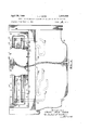
FIG. 1 is a view in vertical cross section of a veneer slicing machine, to which my invention is applied;
FIG. 2 is a fragmentary view of an enlarged scale in vertical elevation of the knife side of the knife carrier of the machine;
FIG. 3 is a view in end elevation of the knife carrier;
FIG. 4 is an end view in partial section of a pressure bar carrier;
FIG. 5 is a vertical, transverse section of a knife carrier employing a modified form of the invention;
FIG. 6 is a similar section on a reduced scale showing a still further modified form;
FIG. 7 is a view in inside vertical elevation of a knife heat equalizer and transfer plate;
FIG. 8 is a vertical section on the line 88 in FIG. 7; and
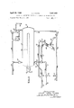
FIG. 9 is a diagram of a heating control and heat transfer fiuid circulating system.
Referring first to FIG. 1, the view is that of a portion of a veneer slicing machine, the total weight of which machine will be several tons in addition to the flitch Weight. The flitch 10 is dogged to a table 11 which is reciprocated diagonally across a number of guide frames one of which being designated by the numeral 12-carried on a bed 13.
Also carried on the bed 13, is a carriage 14, slidably shiftable toward and away from the path of the flitch. A knife and pressure bar carrier generally designated by the numeral 15 is rockably supported by a bearing shaft 16 on the carriage 14.
The knife bar 17 is secured detachably to the carrier 15 to present a cutting edge 18. The carrier 15 is rocked to bring this edge 18 into and out of veneer slicing operation and suitable mechanism (see Patent No. 2,303,213), is supplied to rock the carrier in precise relationship to the travel of the table '11, such mechanism being old and forming per se no part of the present invention. The pressure bar 19 is mounted along the rear edge 20 of a carriage 21 to be adjustably slidably carried by its underside 22 on the surface 23 of the knife carrier 15, FIGS. 3 and 4, so as to be able to secure the proper positioning of the bar 19 in relation to the knife edge 18.
The description of the veneer slicing machine so far presented is old and has been incorporated in machines made for many, many years past, at least as early as in the year 1904, as indicated and described in US. Patent No. 793,306, and in the later US. Patent No. 2,303,213 of 1942, the patentees of both patents having been relatives of the applicant herein.
It is to the foregoing described structure, as one particular example, that applicant applies his invention.
The knife bar carrier 15 is provided with a planar face 24 extending thereacross and having a transverse width slightly less than the Width of the knife bar 17. A pair of laterally spaced apart slots or grooves 25 and 26 are formed to extend back of the face 24 and therealong for a major length of the face 24.
A cover plate 27 is shaped to have approximately parallel, major length sides 28 and 29, and approximately parallel ends 30 and 31. The plate 27 has a planar face 27a placed over the face 24 and is provided with a continuous groove 32 roughly in the shape of an ellipse. This groove 32 has its sides and ends spaced apart to be beyond the confines of the groves 25 and 26. A resilient sealing ring 33 in the nature of an O-ring fits in the plate groove 32 and bears against the face 24 when the plate 27 is brought up theretoward. Fluid is to be circulated into and out of these grooves 25 and 26. The plate 27 and ring 33 forms a seal preventing fluid leakage beyond the confines of the ring 33.
Though the groves 25 and 26 may be interconnected in series, they are illustrated as being connected in parallel, FIG. 2. The carrier 15 is bored as by bores 34 and 35 to intersect respectively end portions of the grooves 25 and 26 as illustrated, FIG. 2. Tubes 36 and 37 connect to the respective bores, one extending along behind the carrier portion supporting the knife bar as a length 37a to approach the other tube 36.
Likewise, FIG. 4, the pressure bar carriage 21 is provided with longitudinal grooves 38 and 39 on the one side of the bar 19, and a groove 40 on the underside somewhat to the rear of the bar 19. Tubes 41, 42 and 43 such as copper, are held in these respective grooves 38, 39 and 40. The tube 41 is connected toward one end with an inlet tube 44 and a tube 45 interconnects the tube 41 with the tube 42. A return tube 46 leads from the tube 42 at a zone remote from the tube 45. The tube 43 is interconnected with the tubes 44 and 46 by the end tubes 47 and 48.
Fluid (water being suflicient if it carries an anti-freeze ingredient when the veneer slicer may be exposed to below freezing temperatures when not operating) is conditioned as to its temperature and circulated by some device auotmatically controlling the temperature under a wide range of slicer operating conditions. One such device is diagrammatically illustrated in FIG. 9. This particular device is commercially obtainable. It is manufactured by Industrial Manufacturing Corp, of Indianapolis, Indiana, and sold under the US. registered trademark Thermolator. The device is not claimed per se.
The tubes 46 and 47 are interconnected with the tubes 37 and 36 respectively. These tubes 36 and 37 lead to the temperature controlling device which is generally designated by the numeral 50. A water heater tank 51 carries internally an electric heating element 52 having external supply wires 53, 54. A water service pipe 55 under normal service supply pressure connects through a check valve 62 to a thermostat 63. The check valve 62 serves to prevent reverse flow.
The tank 51 is provided with an automatic air vent 57 which is connected with a pipe 58. An automatic pressure relief valve 59 is mounted between the tank 51 and the overflow pipe 58. A second automatic relief value 60 is connected to the tank 51 and opens at a higher pressure than is required to open the valve 59. For example, the valve 59 may be set to open at 100 pounds per square inch, and the valve 60 be set to open at 125 pounds. A solenoid operated valve 61 is provided to interconnect the tank 51 directly to the overflow pipe 58.
The thermostat 63 operates to control the operation of heating element 52. A circulating pump 66 takes water from the tank 51 and flows the water through the tube 36 to the knife bar and pressure bar heat transfer tubes. A portion of the pump discharge is by-pas'sed through the pipe 67, through an orifice unit 68 to reduce water flow. The by-pased water flows across an auxiliary electric heating element 80, mixing with the water from the pipe 62, and the resultant tempered water discharges through the pipe 64, and the pipe 64 into the tank 51. The thermostat 63 serves to control through suitable circuitry the major heating element 52, such circuitry not entering per se into my invention.
The temperature of the outfiowing water into the pipe 36 is thus controlled by the device to maintain through heat transfer between the water and the knife 17 and the pressure bar 19 an approximately constant temperature above the dew point of water at the ambient temperature whereby, condensation of moisture on the knife or pressure bar or the carriers is prevented and, in the absence of temperature variation, there is no temperature change induced warping, distortion of those members, and change in dimensions thereof is inhibited.
The grooves 25 and 26 cut in the carrier 23 carry the water to be in direct contact through the cover plate 27 and the knife 17 is in direct contact over the face of the plate 27 and there secured by bolts 70 extending through the plate 27 and screw-threadedly engaging in the carrier 23. The plate 27 is initially attached to the carrier by screws 71. Thus, the plate 27 serves as a heat transfer medium.
As shown in FIGS. 4, 5 and 6, tubes of a material of good heat conduction are inserted within grooves cut from the faces of the pressure bar carrier, or the knife carrier. These tubes in this form are generally designated by the numerial 75. These tubes are imbedded in a plastic 76. Heat conducting elements, such as bits of copper or aluminum are mixed in the plastic to improve the heat transfer. A thinner cover plate 77 may be used as in FIG. 5, to protect the tubes 75 and the plastic 76 in changing knives 17. However, this plate may be omitted and the knife 17 be pressed directly against the face 24, thus providing approximately no distance between the tubes 75 and the knife 17 thereby having the maximum rate of heat transfer to the knife, FIG. 6.
In this heat exchange system the system is always under pressure induced by the service supply. No water will normally be wasted. The cover plate 27 is made out of metal such as the so-called stainless steel, an alloy of aluminum or the like, so that the plate will be a good heat conductor, and the heat fromthe water whether carried in one or a plurality of grooves or tubes may transfuse to bring the entire knife up to the predetermined working temperature and not have the knife to have radically varying temperatures throughout both its width and length. When the plate 27 may be omitted, the carrier itself serves to diffuse the heat over said area. Since the two carriers are preferably made of cast iron and of considerable mass, the mass adjacent to the knife when once brought to the desired temperature, will tend to maintain that temperature and radiate the heat through the knife bearing areas. The knife, of course, is made out of a high grade of steel such as will hold its cutting edge for hours of usage.
In employing the apparatus described, the temperature of the water being circulated is maintained to maintain the temperature of the cutting knife 17 and of the bar 19 above the dew point of water at the ambient temperature. In other words, my method in preventing the veneer staining is to prevent the water from the log from condensing on cold metal and flowing onto the veneer. The log-contained water will normally not be free flowing therefrom and the percentage of water contained in the log will be the same in the veneer. If the metal knife and bar be below the dew point of water, then the moist surface of the log and veneer coming into contact with the colder knife and bar will condense thereon. When the knife and bar are at temperatures above that which would otherwise induce water condensation, the knife and bar remain dry. Hence, by the expedient of maintaining a dry knife and pressure bar, there is no staining.
I claim:
1. A method of obtaining water-stain free veneer being cut in a machine between a knife and a pressure bar from a hot, water-soaked log, which method comprises the steps of circulating a fluid adjacent said knife and said bar, and maintaining an intimate heat-exchanging relation between the knife and the fluid and between the bar and the fluid, said fluid being conditioned to a temperature such as to maintain the knife and the bar at temperatures above the dew point of water at ambient temperatures.
2. A method of obtaining water-stain free veneer being cut in a machine between a knife and a pressure bar from a hot, water-soaked log, which method comprises the steps of supplying heat to the knife by moving a heated fluid in heat-exchanging relation to said knife and supplying heat to the pressure bar by moving a heated fluid in heat-exchanging relation to said pressure bar, while maintaining the temperature and the rate of movement of such fluid at values suflicient to hold the temperature of the knife and of the pressure bar above the dew-point of water at the ambient temperature. 1
3. A method of obtaining water-stain free veneer being cut in a machine between a knife and a pressure bar from a hot, water-soaker log, which method comprises the steps of moving a heated fluid in heat-exchanging relation to said knife and moving a heated fluid in heat-exchanging relation to said pressure bar, While maintaining the temperature and the rate of movement of such fluid at values suflicient to prevent drip of condensate from the knife or from the pressure bar onto the veneer.
References Cited UNITED STATES PATENTS 3,265,103 8/1966 Hervey 144-178 GERALD A. DOST, Primary Examiner.
US. Cl. X.R. 144-178
Applications Claiming Priority (3)
| Application Number | Priority Date | Filing Date | Title |
|---|---|---|---|
| US43774465A | 1965-03-08 | 1965-03-08 | |
| FR52085A FR1485572A (en) | 1966-03-04 | 1966-03-04 | Stabilizing device for cutting blade bars and pressure of veneer slicing machines |
| US65662467A | 1967-07-12 | 1967-07-12 |
Publications (1)
| Publication Number | Publication Date |
|---|---|
| US3441069A true US3441069A (en) | 1969-04-29 |
Family
ID=27242959
Family Applications (1)
| Application Number | Title | Priority Date | Filing Date |
|---|---|---|---|
| US656624A Expired - Lifetime US3441069A (en) | 1965-03-08 | 1967-07-12 | Method of preventing staining of veneers in veneer slicers |
Country Status (2)
| Country | Link |
|---|---|
| US (1) | US3441069A (en) |
| GB (1) | GB1130510A (en) |
Cited By (24)
| Publication number | Priority date | Publication date | Assignee | Title |
|---|---|---|---|---|
| US3654973A (en) * | 1970-10-19 | 1972-04-11 | Capital Machine Co | Hydraulically controlled pressure cap |
| US4083391A (en) * | 1975-05-28 | 1978-04-11 | Angelo Cremona | Wood shearing machine for the production of veneers, having the wood-supporting table inclined to the vertical |
| US4503896A (en) * | 1982-07-30 | 1985-03-12 | Capital Machine Company, Inc. | Dog system for veneer slicer |
| US4587616A (en) * | 1983-05-31 | 1986-05-06 | David R. Webb Co., Inc. | Control system for veneer slicer |
| US4601317A (en) * | 1985-01-31 | 1986-07-22 | Capital Machine Company, Inc. | Veneer slicing system |
| FR2625130A1 (en) * | 1987-12-28 | 1989-06-30 | Martin Michel | LONGITUDINAL WOOD SLICER AND TRENCHING INSTALLATION |
| US5150746A (en) * | 1991-05-17 | 1992-09-29 | David R. Webb Co., Inc. | Flitch table |
| US5381841A (en) * | 1991-05-17 | 1995-01-17 | David R. Webb Co., Inc. | Tangential rotary slicer |
| US5511598A (en) * | 1994-04-05 | 1996-04-30 | Capital Machine Company | Veneer-slicer with remotely controllable blade angle adjustment |
| US5562137A (en) * | 1995-05-31 | 1996-10-08 | Capital Machine Company, Inc. | Method and apparatus for retaining a flitch for cutting |
| US5590700A (en) * | 1995-11-15 | 1997-01-07 | Capital Machine Co., Inc. | Vacuum flitch table with self-cleaning vacuum valve |
| US5680887A (en) * | 1995-11-30 | 1997-10-28 | Capital Machine Co., Inc. | Veneer slicer with timing belt |
| US5694995A (en) * | 1995-05-31 | 1997-12-09 | Capital Machine Company, Inc. | Method and apparatus for preparing a flitch for cutting |
| US5865232A (en) * | 1996-03-08 | 1999-02-02 | Miller Veeners, Inc. | Method and apparatus for cutting veneer sheets from a tapered flitch |
| US5868187A (en) * | 1995-05-31 | 1999-02-09 | Capital Machine Company, Inc. | Method and apparatus for retaining a flitch for cutting |
| US5979524A (en) * | 1997-06-27 | 1999-11-09 | Danzer North America, Inc. | Veneer slicer |
| US5996656A (en) * | 1998-10-26 | 1999-12-07 | Fezer S.A. Industrias Mecanicas | Apparatus for clamping flitches on vertical slicers |
| WO2000010783A1 (en) | 1998-08-20 | 2000-03-02 | Danzer North America, Inc. | Drive system for veneer slicer |
| US6470931B2 (en) | 2000-11-13 | 2002-10-29 | Raute Oyj | Veneer lathe knife assembly |
| US20040177897A1 (en) * | 2003-03-12 | 2004-09-16 | Constantine Edward Joseph | Apparatus and method for manufacturing veneer |
| US20050081955A1 (en) * | 2002-02-04 | 2005-04-21 | Trost Jurgen F. | Veneer slicer |
| US20050230004A1 (en) * | 2004-04-15 | 2005-10-20 | Miller Veneers, Inc. | Method and apparatus for cutting veneer sheets from a flitch |
| US20060086421A1 (en) * | 1998-08-20 | 2006-04-27 | Hartmut Gruender | Drive system for veneer slicer |
| CN101332611B (en) * | 2008-06-16 | 2011-07-20 | 南京林业大学 | Single-plate slicing knife heating system |
Families Citing this family (1)
| Publication number | Priority date | Publication date | Assignee | Title |
|---|---|---|---|---|
| SE431175B (en) * | 1982-11-30 | 1984-01-23 | Tarkett Ab | SET FOR FAN CUTTING |
Citations (1)
| Publication number | Priority date | Publication date | Assignee | Title |
|---|---|---|---|---|
| US3265103A (en) * | 1964-02-11 | 1966-08-09 | David E Hervey | Wood veneer slicing elements temperature maintenance means |
-
1966
- 1966-01-25 GB GB3282/66A patent/GB1130510A/en not_active Expired
-
1967
- 1967-07-12 US US656624A patent/US3441069A/en not_active Expired - Lifetime
Patent Citations (1)
| Publication number | Priority date | Publication date | Assignee | Title |
|---|---|---|---|---|
| US3265103A (en) * | 1964-02-11 | 1966-08-09 | David E Hervey | Wood veneer slicing elements temperature maintenance means |
Cited By (43)
| Publication number | Priority date | Publication date | Assignee | Title |
|---|---|---|---|---|
| US3654973A (en) * | 1970-10-19 | 1972-04-11 | Capital Machine Co | Hydraulically controlled pressure cap |
| US4083391A (en) * | 1975-05-28 | 1978-04-11 | Angelo Cremona | Wood shearing machine for the production of veneers, having the wood-supporting table inclined to the vertical |
| US4503896A (en) * | 1982-07-30 | 1985-03-12 | Capital Machine Company, Inc. | Dog system for veneer slicer |
| US4587616A (en) * | 1983-05-31 | 1986-05-06 | David R. Webb Co., Inc. | Control system for veneer slicer |
| US4601317A (en) * | 1985-01-31 | 1986-07-22 | Capital Machine Company, Inc. | Veneer slicing system |
| FR2625130A1 (en) * | 1987-12-28 | 1989-06-30 | Martin Michel | LONGITUDINAL WOOD SLICER AND TRENCHING INSTALLATION |
| EP0322646A1 (en) * | 1987-12-28 | 1989-07-05 | Michel Martin | Longitudinal wood veneer slicer |
| US4917159A (en) * | 1987-12-28 | 1990-04-17 | Michel Martin | Longitudinal wood peeling machine and a wood peeling installation |
| US5381841A (en) * | 1991-05-17 | 1995-01-17 | David R. Webb Co., Inc. | Tangential rotary slicer |
| WO1992020501A1 (en) * | 1991-05-17 | 1992-11-26 | David R. Webb Co., Inc. | Tangential rotary veneer slicer |
| US5150746A (en) * | 1991-05-17 | 1992-09-29 | David R. Webb Co., Inc. | Flitch table |
| US5511598A (en) * | 1994-04-05 | 1996-04-30 | Capital Machine Company | Veneer-slicer with remotely controllable blade angle adjustment |
| US7395843B1 (en) | 1995-05-31 | 2008-07-08 | Indiana Forge, Llc | Method and apparatus for retaining a flitch for cutting |
| US5562137A (en) * | 1995-05-31 | 1996-10-08 | Capital Machine Company, Inc. | Method and apparatus for retaining a flitch for cutting |
| US5678619A (en) * | 1995-05-31 | 1997-10-21 | Capital Machine Co., Inc. | Method and apparatus for cutting veneer from a tapered flitch |
| US5694995A (en) * | 1995-05-31 | 1997-12-09 | Capital Machine Company, Inc. | Method and apparatus for preparing a flitch for cutting |
| US5701938A (en) * | 1995-05-31 | 1997-12-30 | Capital Machine Company, Inc. | Method and apparatus for retaining a flitch for cutting |
| US5868187A (en) * | 1995-05-31 | 1999-02-09 | Capital Machine Company, Inc. | Method and apparatus for retaining a flitch for cutting |
| US5590700A (en) * | 1995-11-15 | 1997-01-07 | Capital Machine Co., Inc. | Vacuum flitch table with self-cleaning vacuum valve |
| US5680887A (en) * | 1995-11-30 | 1997-10-28 | Capital Machine Co., Inc. | Veneer slicer with timing belt |
| US5865232A (en) * | 1996-03-08 | 1999-02-02 | Miller Veeners, Inc. | Method and apparatus for cutting veneer sheets from a tapered flitch |
| US5979524A (en) * | 1997-06-27 | 1999-11-09 | Danzer North America, Inc. | Veneer slicer |
| US20060086421A1 (en) * | 1998-08-20 | 2006-04-27 | Hartmut Gruender | Drive system for veneer slicer |
| US6102090A (en) * | 1998-08-20 | 2000-08-15 | Danzer North America, Inc. | Flitch table mounting |
| US20110155282A1 (en) * | 1998-08-20 | 2011-06-30 | Hartmut Gruender | Drive system for veneer slicer |
| WO2000010783A1 (en) | 1998-08-20 | 2000-03-02 | Danzer North America, Inc. | Drive system for veneer slicer |
| US7025099B1 (en) | 1998-08-20 | 2006-04-11 | Danzer North America, Inc. | Drive system for veneer slicer |
| EP1905536A1 (en) | 1998-08-20 | 2008-04-02 | Danzer North America Inc. | Drive mechanism |
| US5996656A (en) * | 1998-10-26 | 1999-12-07 | Fezer S.A. Industrias Mecanicas | Apparatus for clamping flitches on vertical slicers |
| US6470931B2 (en) | 2000-11-13 | 2002-10-29 | Raute Oyj | Veneer lathe knife assembly |
| US20050081955A1 (en) * | 2002-02-04 | 2005-04-21 | Trost Jurgen F. | Veneer slicer |
| US20070215244A1 (en) * | 2002-02-04 | 2007-09-20 | Danzer North America, Inc. | Veneer slicer |
| US7918253B2 (en) | 2002-02-04 | 2011-04-05 | Padana Ag | Veneer slicer |
| US7426947B2 (en) | 2002-02-04 | 2008-09-23 | Danzer North America, Inc. | Veneer slicer |
| US7458404B2 (en) | 2002-02-04 | 2008-12-02 | Danzer North America, Inc. | Veneer slicer |
| US20090078338A1 (en) * | 2002-02-04 | 2009-03-26 | Danzer North America, Inc. | Veneer slicer |
| US7028729B2 (en) | 2003-03-12 | 2006-04-18 | Apollo Hardwoods Co Llc | Apparatus and method for manufacturing veneer |
| US20040177897A1 (en) * | 2003-03-12 | 2004-09-16 | Constantine Edward Joseph | Apparatus and method for manufacturing veneer |
| US20050230004A1 (en) * | 2004-04-15 | 2005-10-20 | Miller Veneers, Inc. | Method and apparatus for cutting veneer sheets from a flitch |
| US20090308495A1 (en) * | 2004-04-15 | 2009-12-17 | Miller Veneers, Inc. | Method and apparatus for cutting veneer sheets from a flitch |
| US7967043B2 (en) | 2004-04-15 | 2011-06-28 | Miller Vaneers, Inc. | Method and apparatus for cutting veneer sheets from a flitch |
| US7552750B2 (en) | 2004-04-15 | 2009-06-30 | Miller Veneers, Inc. | Method and apparatus for cutting veneer sheets from a flitch |
| CN101332611B (en) * | 2008-06-16 | 2011-07-20 | 南京林业大学 | Single-plate slicing knife heating system |
Also Published As
| Publication number | Publication date |
|---|---|
| GB1130510A (en) | 1968-10-16 |
Similar Documents
| Publication | Publication Date | Title |
|---|---|---|
| US3441069A (en) | Method of preventing staining of veneers in veneer slicers | |
| Lutz | Techniques for peeling, slicing and drying veneer | |
| US2202110A (en) | Woodwork incising machine | |
| US3838722A (en) | Trimming apparatus | |
| US4602663A (en) | Veneer lathe with powered nose bar roll of large diameter | |
| US1815670A (en) | Wood slicing machine | |
| US4516614A (en) | Method of slicing veneer | |
| DE20206407U1 (en) | Drying station construction for printing press located along circumference of tempering roller, drying printed surface and cooling rear surface to prevent shrinkage | |
| US2985205A (en) | Wood shaping machine provided with multi-surface cutting units | |
| US4416069A (en) | Enhancement of color quality of lumber during drying | |
| US7028729B2 (en) | Apparatus and method for manufacturing veneer | |
| Lutz | Heating veneer bolts to improve quality of Douglas-fir plywood | |
| US2692118A (en) | Method and apparatus for controlling the temperature of rolls | |
| US3397723A (en) | Method of preparing flitches for veneer cutting machines | |
| US6398885B1 (en) | Method and apparatus for preventing cracking of the shank junction of die blocks | |
| US2644495A (en) | Routing machine for removing defects from wood | |
| SU390952A1 (en) | HORIZONTAL FANEROSTROGALNY MACHINE | |
| US2805694A (en) | Waferer | |
| US3580792A (en) | Lumber and veneer jointer | |
| US2293103A (en) | Grinder for grinding the pressure bars of veneer cutting machines | |
| US348051A (en) | Manufacture of sheets of veneer | |
| FORESTPRODUCTSLABORAT | HEATING RATES FOR LOGS, BOLTS, AND FLITCHES TO BE CUT INTO VENEER | |
| Mathewson | High-temperature drying: Its application to the drying of lumber | |
| US2184862A (en) | Veneer machine | |
| EP0158580A1 (en) | Timber production |