EP1480403A1 - Demodulating apparatus and demodulating method - Google Patents
Demodulating apparatus and demodulating method Download PDFInfo
- Publication number
- EP1480403A1 EP1480403A1 EP03705376A EP03705376A EP1480403A1 EP 1480403 A1 EP1480403 A1 EP 1480403A1 EP 03705376 A EP03705376 A EP 03705376A EP 03705376 A EP03705376 A EP 03705376A EP 1480403 A1 EP1480403 A1 EP 1480403A1
- Authority
- EP
- European Patent Office
- Prior art keywords
- section
- received signal
- demodulation
- amplitude
- averaging
- Prior art date
- Legal status (The legal status is an assumption and is not a legal conclusion. Google has not performed a legal analysis and makes no representation as to the accuracy of the status listed.)
- Withdrawn
Links
Images




Classifications
-
- H—ELECTRICITY
- H04—ELECTRIC COMMUNICATION TECHNIQUE
- H04L—TRANSMISSION OF DIGITAL INFORMATION, e.g. TELEGRAPHIC COMMUNICATION
- H04L25/00—Baseband systems
- H04L25/02—Details ; arrangements for supplying electrical power along data transmission lines
- H04L25/06—DC level restoring means; Bias distortion correction ; Decision circuits providing symbol by symbol detection
- H04L25/067—DC level restoring means; Bias distortion correction ; Decision circuits providing symbol by symbol detection providing soft decisions, i.e. decisions together with an estimate of reliability
Definitions
- the present invention relates to a demodulation apparatus and demodulation method applied to a communication terminal apparatus and base station apparatus in a radio communication system.
- M-ary Quadrature Amplitude Modulation M-ary Quadrature Amplitude Modulation
- M-ary Quadrature Amplitude Modulation for example, in 16QAM, in order to demodulate modulated signals, it is required to bring a scale of amplitude of a received signal point into coincidence with a scale of amplitude of a reference signal point that is a reference in demodulation.
- the processing is generally called amplitude variation compensation.
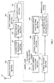
- FIG.1 is a block diagram showing an example of a configuration of a demodulation apparatus according to the first embodiment of the present invention.
- the radio communication apparatus has antenna 101, radio reception section 102, correlation processing section 103, delay profile generating section 104, Rake combining section 105, JD computation section 106, symbol dividing section 107, symbol averaging section 108, reference signal point setting section 109 and soft decision value calculating section 110.
- Radio reception section 102 performs predetermined radio processing such as down converting on a signal received in antenna 101.
- Correlation processing section 103 performs correlation calculations between a pilot signal portion called midamble contained in a received signal output from radio reception section 102 and a known midamble sequence to output to delay profile generating section 104.
- Delay profile generating section 104 generates a delay profile of the signal output from correlation processing section 103 to output to Rake combining section 105. Using the delay profile, Rake combining section 105 performs despreading and Rake combining on the received signal to output to JD computation section 106.
- JD computation section 106 Based on the received signal subjected to Rake combining in Rake combining section 105 and the delay profile generated in delay profile generating section 104, JD computation section 106 performs JD computation processing on the received signal over a single time slot to output to symbol dividing section 107.
- the JD computation is of a computation method as described in Japanese Patent Application 2001-156625, for example.
- Symbol dividing section 107 divides the received signal output from JD computation section 106 into beforehand set intervals to output to soft decision value calculating section 110 and symbol averaging section 108.
- Symbol averaging section 108 averages divided received signals output from symbol dividing section 107 to obtain average amplitude of the received signals, and outputs the average amplitude to reference signal point setting section 109.
- reference signal point setting section 109 sets reference signals used in demodulation to output to soft decision value calculating section 110.
- Soft decision value calculating section 110 makes a soft decision on received signals output from symbol dividing section 107, using the reference signal points set in reference signal point setting section 109. The calculated soft decision value is output as a demodulated signal.
- a signal modulated in M-ary modulation such as 16QAM
- data decision is made by comparing a received signal point with reference signal points.
- the decision it is required to equalize in scale the received signal point and reference signal points.
- it is required to compensate for amplitude variations occurring in a received signal due to effects of fading, for example, on propagation paths.
- a common pilot signal is used, and reception power of the common pilot signal is used in amplitude variation compensation.
- a midamble portion containing a pilot signal is not always the same in scale as a received symbol, and further, a signal subjected to JD computation processing does not always have the same reception power as that obtained from the midamble portion. Therefore, it is not possible to perform amplitude variation compensation using a pilot signal.
- average amplitude of received symbols over a single slot is assumed to be X
- average amplitude of beforehand set sixteen reference signal points is assumed to be y
- decision on a QAM symbol point is made by comparing the received symbol subjected to JD computation processing to the reference signal points each multiplied by ⁇ .
- the demodulation accuracy over a single slot in a conventional apparatus is as described below.
- a scale of reference signal points obtained from the average amplitude is almost equal to a scale of signal points of a received symbol, demodulation accuracy is high.
- a scale of reference signal points differs from a scale of signal points of a received symbol, demodulation accuracy is low.
- Data 1 represents a data portion disposed before a midamble portion
- data 2 represents a data portion disposed after the midamble portion.
- reference signal points are set for each of the divided intervals, and the decision is made on a received signal using respective reference signal points. It is thereby possible to prevent deterioration of demodulation accuracy caused by an error in amplitude between reference signal points and received symbol.
- FIG.5 is a graph showing a plot of experimentally obtained demodulation accuracy when a slot is divided into N intervals.
- a single slot is divided into N intervals, and the amplitude variation compensation is carried out in each of the intervals, whereby it is possible to improve the accuracy in average amplitude of received signal points, and to improve the demodulation accuracy.
- the optional processing is only to divide a slot into N intervals, techniques in the present invention can be applied readily to existing mobile communication systems.
- FIG.6 is a block diagram showing an example of a configuration of a demodulation apparatus according to the second embodiment of the present invention.
- the demodulation apparatus has basically the same configuration as that of the demodulation apparatus as shown in FIG.1, and the same structural elements are respectively assigned the same reference numerals to omit descriptions thereof.
- the apparatus further has fading speed calculating section 601 and dividing number calculating section 602 to determine the dividing number of a slot corresponding to propagation path environments.
- Delay profile generating section 104 outputs a generated delay profile to fading speed calculating section 601.
- ⁇ T frame is the duration of a frame [sec].
- Dividing number calculating section 602 calculates minimum natural number N that satisfies an equation of (V f ⁇ ⁇ T slot /N) ⁇ P th , where T slot is a time length of a data portion (except a pilot portion, i.e., midamble portion) of a transmission unit (slot), and P th is a predetermined threshold.
- calculated N is set as a dividing number in symbol dividing section 107, and subsequently, the received signal undergoes the same processing as in the first embodiment.
- a time sequence is divided into time units each called a frame, a frame is divided into time units each called a time slot, and signals are transmitted on a time-slot basis.
- FIG.7 is a block diagram showing an example of a configuration of a demodulation apparatus according to the third embodiment of the present invention.
- the demodulation apparatus has basically the same configuration as that of the demodulation apparatus as shown in FIG.1, and the same structural elements are respectively assigned the same reference numerals to omit descriptions thereof.
- the apparatus further has dividing number calculating section 701.
- Symbol dividing section 107 divides a signal of 1 slot output from JD computation section 106 byN calculated in dividing number calculating section 701.
- averaging intervals for amplitude variation compensation of a received signal are set corresponding to the number of multiplexed codes of the received signal, it is possible to prevent occurrences of the case that a small number of multiplexed codes result in a small number of symbols to average and the averaging is not carried out adequately, and to improve the demodulation accuracy.
- FIG.8 is a block diagram showing an example of a configuration of a demodulation apparatus according to the fourth embodiment of the present invention.
- the demodulation apparatus has basically the same configuration as that of the demodulation apparatus as shown in FIG.1, and the same structural elements are respectively assigned the same reference numerals to omit descriptions thereof.
- the apparatus has dividing number calculating section 801.
- JD computation section 106 outputs a received signal subjected to JD computation to symbol dividing section 107 and dividing number calculating section 801.
- Dividing number calculating section 801 calculates N such that the number of symbols divided by N (N symbol /N) does not decrease below the predetermined constant number of symbols, N const , using the number of symbols, N symbol , demodulated in JD computation section 106.
- the obtained N is output to symbol dividing section 107, and is used in dividing a signal of 1 slot output from JD computation section 106. It is thereby possible to ensure the number of symbols per averaging interval for amplitude variation compensation of a received signal more than or equal to a predetermined value.
- averaging intervals for amplitude variation compensation of a received signal are set corresponding to the number of symbols of the intervals, it is possible to prevent occurrences of the case that averaging is not carried out adequately due to a small number of symbols to average, and to improve the demodulation accuracy.
- FIG.9 is a block diagram showing an example of a configuration of a demodulation apparatus according to the fifth embodiment of the present invention.
- the demodulation apparatus has basically the same configuration as that of the demodulation apparatus as shown in FIG.6, and the same structural elements are respectively assigned the same reference numerals to omit descriptions thereof.
- the apparatus has symbol averaging section 901.
- Fading speed calculating section 601 outputs calculated fading speed to symbol averaging section 901.
- symbol averaging section 901 obtains an average value of N center symbols in a center portion of a slot of the received signal output from JD computation section 106. Then, with respect to symbols except the N center symbols, the section 901 also outputs the average value obtained for the N center symbols. Accordingly, the average value obtained for the N center symbols is output to reference signal point setting section 109 over the entire averaging intervals.
- an average value is calculated for part of an averaging interval for amplitude variation compensation, and is used as an average value for the averaging interval, and it is thereby possible to minimize the number of symbols used in averaging, and to suppress power consumption. Further, it is possible to reduce the time required for averaging.
- Each of the demodulation apparatuses according to the present invention is capable of being provided in a communication terminal apparatus and base station apparatus using the same system as described above, and it is thereby possible to provide the communication terminal apparatus and base station apparatus with the same advantages as described above.
- averaging intervals for amplitude variation compensation of a received signal are varied corresponding to an amplitude variation on propagation paths of the received signal, and it is thereby possible to improve the accuracy in average amplitude of received signal points, and to improve the demodulation accuracy.
- the present invention is applicable to a demodulation apparatus provided in a communication terminal apparatus and base station apparatus in a radio communication system.
Landscapes
- Engineering & Computer Science (AREA)
- Power Engineering (AREA)
- Computer Networks & Wireless Communication (AREA)
- Signal Processing (AREA)
- Digital Transmission Methods That Use Modulated Carrier Waves (AREA)
- Mobile Radio Communication Systems (AREA)
Abstract
A signal received in an antenna (101) is input to
a symbol dividing section (107) via a radio reception
section (102), delay profile generating section (104),
Rake combining section (105), and JD computation section
(106), is divided every a predetermined number of symbols,
and is output to a soft decision value calculating section
(110) and symbol averaging section (108). The symbol
averaging section (108) obtains average amplitude of
divided received signals. A reference signal point
setting section (109) sets reference signal points based
on the average amplitude. The soft decision value
calculating section (110) makes a soft decision on the
received signal output from the symbol dividing section
(107), using the reference signal points set in reference
signal point setting section (109). It is thereby
possible to improve the accuracy in average amplitude
of received signal points and to improve the demodulation
accuracy.
Description
- The present invention relates to a demodulation apparatus and demodulation method applied to a communication terminal apparatus and base station apparatus in a radio communication system.
- Recently, as a modulation scheme in digital radio communications that cope with increased communication needs, amplitude modulation that provides the amplitude with information has been implemented such as M-ary Quadrature Amplitude Modulation (M-ary QAM).
- In the M-ary Quadrature Amplitude Modulation, for example, in 16QAM, in order to demodulate modulated signals, it is required to bring a scale of amplitude of a received signal point into coincidence with a scale of amplitude of a reference signal point that is a reference in demodulation. The processing is generally called amplitude variation compensation.
- Specifically, average amplitude of received signal points and average amplitude of reference signal points is obtained, ratio a (=the average amplitude of received signal points/the average amplitude of reference signal points) is calculated, and α is multiplied by each of the reference signal points, thereby performing the amplitude variation compensation.
- At this point, it is required to carry out the averaging over symbols for the long term to obtain the average amplitude of received signal points with high accuracy. However, averaging the amplitude for the long term increases a difference between the average amplitude and instantaneous amplitude due to an effect of reception power variation caused by, for example, fading, a significant error thereby occurs between a reception signal point and reference signal point used in demodulation, and there arises a problem that demodulation characteristics of the received signal deteriorate.
- Meanwhile, when the number of symbols to average is small, the accuracy in average amplitude deteriorates, and also the problem arises that demodulation characteristics deteriorate.
- It is an object of the present invention to provide a demodulation apparatus and demodulation method that enable improved accuracy in average amplitude of received signal points and improved demodulation accuracy.
- It is a subject matter of the present invention to divide a demodulation interval in M-ary Quadrature Amplitude Modulation corresponding to an amplitude variation in received signal or data amount of the received signal so as to set an averaging interval used in amplitude variation compensation of the received signal at an optimal interval.
-
- FIG.1 is a block diagram showing an example of a configuration of a demodulation apparatus according to a first embodiment of the present invention;
- FIG.2 is a view showing reference signal points before and after amplitude variation compensation;
- FIG.3 is a view showing changes in demodulation accuracy in a slot in a conventional apparatus;
- FIG.4 is a view showing a configuration of a slot of a received signal when dividing number N is four (N=4);
- FIG.5 is a graph of demodulation accuracy when a slot is divided into N intervals;
- FIG.6 is a block diagram showing an example of a configuration of a demodulation apparatus according to a second embodiment of the present invention;
- FIG.7 is a block diagram showing an example of a configuration of a demodulation apparatus according to a third embodiment of the present invention;
- FIG.8 is a block diagram showing an example of a configuration of a demodulation apparatus according to a fourth embodiment of the present invention; and
- FIG.9 is a block diagram showing an example of a configuration of demodulation apparatus according to a fifth embodiment of the present invention.
-
- Embodiments of the present invention will be described specifically below with reference to accompanying drawings. Herein, descriptions are given using as an example a case where an IMT2000-TDD (International Mobile Telecommunications 2000 Time Division Duplex) system is used in a HSDPA (High Speed Downlink Packet Access) specified in 3GPP (3rd Generation Partnership Project) TR25.848 v4.0.0(2001-03), and a signal modulated in 16QAM is demodulated.
- FIG.1 is a block diagram showing an example of a configuration of a demodulation apparatus according to the first embodiment of the present invention.
- The radio communication apparatus has
antenna 101,radio reception section 102,correlation processing section 103, delayprofile generating section 104, Rake combiningsection 105,JD computation section 106,symbol dividing section 107,symbol averaging section 108, reference signalpoint setting section 109 and soft decisionvalue calculating section 110. -
Radio reception section 102 performs predetermined radio processing such as down converting on a signal received inantenna 101.Correlation processing section 103 performs correlation calculations between a pilot signal portion called midamble contained in a received signal output fromradio reception section 102 and a known midamble sequence to output to delayprofile generating section 104. Delayprofile generating section 104 generates a delay profile of the signal output fromcorrelation processing section 103 to output to Rake combiningsection 105. Using the delay profile, Rake combiningsection 105 performs despreading and Rake combining on the received signal to output toJD computation section 106. Based on the received signal subjected to Rake combining in Rake combiningsection 105 and the delay profile generated in delayprofile generating section 104,JD computation section 106 performs JD computation processing on the received signal over a single time slot to output to symbol dividingsection 107. Herein, the JD computation is of a computation method as described in Japanese Patent Application 2001-156625, for example. -
Symbol dividing section 107 divides the received signal output fromJD computation section 106 into beforehand set intervals to output to soft decisionvalue calculating section 110 andsymbol averaging section 108. -
Symbol averaging section 108 averages divided received signals output fromsymbol dividing section 107 to obtain average amplitude of the received signals, and outputs the average amplitude to reference signalpoint setting section 109. - Based on the average amplitude of the received signals output from
symbol averaging section 108, reference signalpoint setting section 109 sets reference signals used in demodulation to output to soft decisionvalue calculating section 110. - Specifically, the
section 109 calculates α (=average amplitude of received signals/average amplitude of reference signals) that is a ratio of average amplitude of received signals to average amplitude of beforehand set reference signals, and multiplies α by each of reference signal points to set final reference signal points. - Soft decision
value calculating section 110 makes a soft decision on received signals output fromsymbol dividing section 107, using the reference signal points set in reference signalpoint setting section 109. The calculated soft decision value is output as a demodulated signal. - The principle of the demodulation scheme as described above will be described below.
- When a signal modulated in M-ary modulation such as 16QAM is demodulated, data decision is made by comparing a received signal point with reference signal points. In the decision, it is required to equalize in scale the received signal point and reference signal points. In other words, in order to perform more accurate demodulation, it is required to compensate for amplitude variations occurring in a received signal due to effects of fading, for example, on propagation paths.
- In a FDD (Frequency Division Duplex) system, a common pilot signal is used, and reception power of the common pilot signal is used in amplitude variation compensation. However, in the TDD system, a midamble portion containing a pilot signal is not always the same in scale as a received symbol, and further, a signal subjected to JD computation processing does not always have the same reception power as that obtained from the midamble portion. Therefore, it is not possible to perform amplitude variation compensation using a pilot signal.
- Accordingly, it is necessary to determine a scale of amplitude of reference signals that are references in demodulation. Hence, in the present invention, average amplitude of received symbols of a data portion is used.
- As shown in FIG.2, average amplitude of received symbols over a single slot is assumed to be X, average amplitude of beforehand set sixteen reference signal points is assumed to be y, and each of the beforehand set reference signals points is multiplied by x/y (=α), thereby equalizing scales of received signal points and reference signal points. Then, decision on a QAM symbol point is made by comparing the received symbol subjected to JD computation processing to the reference signal points each multiplied by α.
- In obtaining the average amplitude of received symbols, in order to improve the accuracy in average value, a sufficient number of symbols should be used. However, performing the averaging for the long term increases a difference between the average amplitude and instantaneous amplitude due to an effect of power variation caused by fading, and a significant error occurs in scale between a received symbol and reference signal points usedin demodulation. As a result, demodulation characteristics deteriorate.
- For example, when the amplitude of received signal varies as shown in FIG.3, the demodulation accuracy over a single slot in a conventional apparatus is as described below. In a symbol in a center portion of the slot, since a scale of reference signal points obtained from the average amplitude is almost equal to a scale of signal points of a received symbol, demodulation accuracy is high. Meanwhile, at opposite ends of the slot, since a scale of reference signal points differs from a scale of signal points of a received symbol, demodulation accuracy is low.
- Then, in the present invention, in order for the problem as described above not to occur, a slot is divided into appropriate intervals. FIG.4 shows an example where dividing number N is four (N=4).
Data 1 represents a data portion disposed before a midamble portion, anddata 2 represents a data portion disposed after the midamble portion. - Using average amplitude values x1 to x4 respectively of divided intervals, reference signal points are set for each of the divided intervals, and the decision is made on a received signal using respective reference signal points. It is thereby possible to prevent deterioration of demodulation accuracy caused by an error in amplitude between reference signal points and received symbol.
- FIG.5 is a graph showing a plot of experimentally obtained demodulation accuracy when a slot is divided into N intervals. Plots P1, P2, P3 and P4 represent demodulation accuracy curves for N=1, N=2, N=4 and N=8, respectively.
- For example, it is understood that when received signal energy near a noise level (Ec/NO) is large, increased dividing number N remarkably improves BLER (Block Error Rate) representing demodulation accuracy.
- Thus, according to this embodiment, a single slot is divided into N intervals, and the amplitude variation compensation is carried out in each of the intervals, whereby it is possible to improve the accuracy in average amplitude of received signal points, and to improve the demodulation accuracy. Further, since the optional processing is only to divide a slot into N intervals, techniques in the present invention can be applied readily to existing mobile communication systems.
- FIG.6 is a block diagram showing an example of a configuration of a demodulation apparatus according to the second embodiment of the present invention. In addition, the demodulation apparatus has basically the same configuration as that of the demodulation apparatus as shown in FIG.1, and the same structural elements are respectively assigned the same reference numerals to omit descriptions thereof.
- It is a feature of this embodiment that the apparatus further has fading
speed calculating section 601 and dividingnumber calculating section 602 to determine the dividing number of a slot corresponding to propagation path environments. - Delay
profile generating section 104 outputs a generated delay profile to fadingspeed calculating section 601. - Using delay profiles output from delay
profile generating section 104, fadingspeed calculating section 601 measures total path power Pi in a delay profile of an ith frame and total path power Pi+1 in a delay profile of an (i+1)th frame, and obtains difference ΔP (=Pi+1-Pi) in reception power between frames. Then, thesection 104 calculates fading speed Vf(ΔP/ΔTframe) to output to dividingnumber calculating section 602. Herein, ΔTframe is the duration of a frame [sec]. - Dividing
number calculating section 602 calculates minimum natural number N that satisfies an equation of (Vf× Δ Tslot/N)<Pth, where Tslot is a time length of a data portion (except a pilot portion, i.e., midamble portion) of a transmission unit (slot), and Pth is a predetermined threshold. - Then, calculated N is set as a dividing number in
symbol dividing section 107, and subsequently, the received signal undergoes the same processing as in the first embodiment. - In the above description, a time sequence is divided into time units each called a frame, a frame is divided into time units each called a time slot, and signals are transmitted on a time-slot basis.
- Thus, according to this embodiment, since averaging intervals for amplitude variation compensation are set corresponding to fading speed on propagation paths of received signal, it is possible to obtain appropriate average amplitude of received signal even when fading occurs at high speed, and to improve the demodulation accuracy.
- FIG.7 is a block diagram showing an example of a configuration of a demodulation apparatus according to the third embodiment of the present invention. In addition, the demodulation apparatus has basically the same configuration as that of the demodulation apparatus as shown in FIG.1, and the same structural elements are respectively assigned the same reference numerals to omit descriptions thereof.
- It is a feature of this embodiment that the apparatus further has dividing
number calculating section 701. - Dividing
number calculating section 701 calculates maximum integer number N less than or equal to Ncode/Nconst, using the number of multiplexed codes, Ncode, notified from an upper layer. In other words, thesection 701 calculates N such that the number of multiplexed codes per divided interval (Ncode/N) is more than or equal to predetermined constant value Nconst to output tosymbol dividing section 107. For example, when Ncode/Nconst = 2.2, N is two (N=2). -
Symbol dividing section 107 divides a signal of 1 slot output fromJD computation section 106 byN calculated in dividingnumber calculating section 701. - Thus, according to this embodiment, since averaging intervals for amplitude variation compensation of a received signal are set corresponding to the number of multiplexed codes of the received signal, it is possible to prevent occurrences of the case that a small number of multiplexed codes result in a small number of symbols to average and the averaging is not carried out adequately, and to improve the demodulation accuracy.
- FIG.8 is a block diagram showing an example of a configuration of a demodulation apparatus according to the fourth embodiment of the present invention. In addition, the demodulation apparatus has basically the same configuration as that of the demodulation apparatus as shown in FIG.1, and the same structural elements are respectively assigned the same reference numerals to omit descriptions thereof.
- It is a feature of this embodiment that the apparatus has dividing
number calculating section 801. -
JD computation section 106 outputs a received signal subjected to JD computation tosymbol dividing section 107 and dividingnumber calculating section 801. - Dividing
number calculating section 801 calculates N such that the number of symbols divided by N (Nsymbol/N) does not decrease below the predetermined constant number of symbols, Nconst, using the number of symbols, Nsymbol, demodulated inJD computation section 106. In other words, thesection 701 calculates maximum integer N less than or equal to Nsymbol/Nconst when Nsymbol is more than Nconst (Nsymbol>Nconst), while setting N at 1 (N=1) when Nsymbol is less than or equal to Nconst (Nsymbol≦Nconst). - The obtained N is output to
symbol dividing section 107, and is used in dividing a signal of 1 slot output fromJD computation section 106. It is thereby possible to ensure the number of symbols per averaging interval for amplitude variation compensation of a received signal more than or equal to a predetermined value. - Thus, according to this embodiment, since averaging intervals for amplitude variation compensation of a received signal are set corresponding to the number of symbols of the intervals, it is possible to prevent occurrences of the case that averaging is not carried out adequately due to a small number of symbols to average, and to improve the demodulation accuracy.
- FIG.9 is a block diagram showing an example of a configuration of a demodulation apparatus according to the fifth embodiment of the present invention. In addition, the demodulation apparatus has basically the same configuration as that of the demodulation apparatus as shown in FIG.6, and the same structural elements are respectively assigned the same reference numerals to omit descriptions thereof.
- It is a feature of this embodiment that the apparatus has
symbol averaging section 901. - Fading
speed calculating section 601 outputs calculated fading speed tosymbol averaging section 901. - When fading speed Vf output from fading
speed calculating section 601 is less than or equal to a predetermined value,symbol averaging section 901 obtains an average value of Ncenter symbols in a center portion of a slot of the received signal output fromJD computation section 106. Then, with respect to symbols except the Ncenter symbols, thesection 901 also outputs the average value obtained for the Ncenter symbols. Accordingly, the average value obtained for the Ncenter symbols is output to reference signalpoint setting section 109 over the entire averaging intervals. - Thus, according to this embodiment, when fading variations are small on propagation paths, an average value is calculated for part of an averaging interval for amplitude variation compensation, and is used as an average value for the averaging interval, and it is thereby possible to minimize the number of symbols used in averaging, and to suppress power consumption. Further, it is possible to reduce the time required for averaging.
- Each of the demodulation apparatuses according to the present invention is capable of being provided in a communication terminal apparatus and base station apparatus using the same system as described above, and it is thereby possible to provide the communication terminal apparatus and base station apparatus with the same advantages as described above.
- In addition, descriptions are given using as an example the case where the IMT2000-TDD system is used in the HSDPA (High Speed Downlink Packet Access) based on specifications of 3GPP (3rd Generation Partnership Project) TR25.848 v4.0.0 (2001-03), and asignal modulated in 16QAM is demodulated. However, the present invention is not limited to such a case, and is applicable to systems with the same characteristics as those described above.
- As described above, according to the present invention, averaging intervals for amplitude variation compensation of a received signal are varied corresponding to an amplitude variation on propagation paths of the received signal, and it is thereby possible to improve the accuracy in average amplitude of received signal points, and to improve the demodulation accuracy.
- This application is based on the Japanese Patent Application No.2002-050002 filed on February 26, 2002, entire content of which is expressly incorporated by reference herein.
- The present invention is applicable to a demodulation apparatus provided in a communication terminal apparatus and base station apparatus in a radio communication system.
Claims (10)
- A demodulation apparatus comprising:a dividing section that divides a time slot that is a unit for symbol reproduction of a received signal into a plurality of intervals;a setting section that sets reference signal points that are references used in demodulating the received signal for each of the intervals, using amplitude of a data portion of the received signal in each of the intervals divided; anda demodulation section that demodulates the received signal in the each of the intervals using the reference signal points set.
- A demodulation apparatus comprising:a dividing section that divides a received signal sequence of unit demodulation length corresponding to a variation in amplitude of a received signal;an averaging section that averages amplitude of each of received signal sequences divided in the dividing section;a setting section that sets reference signal points in quadrature amplitude demodulation for the received signal using the amplitude averaged in the averaging section; anda demodulation section that demodulates the each of the received signal sequences using the reference signal points set.
- The demodulation apparatus according to claim 2, further comprising:wherein the dividing section divides the received signal sequence of unit demodulation length corresponding to the fading speed calculated in the calculating section.a calculating section that calculates fading speed of a received signal;
- A demodulation apparatus comprising:a dividing section that divides a received signal sequence of unit demodulation length corresponding to a data amount of the received signal;an averaging section that averages amplitude of each of received signal sequences divided in the dividing section;a setting section that sets reference signal points in quadrature amplitude demodulation for the received signal using the amplitude averaged in the averaging section; anda demodulation section that demodulates the each of the received signal sequences using the reference signal points set.
- The demodulation apparatus according to claim 4, wherein the dividing section divides the received signal sequence of unit demodulation length corresponding to a multiplexing number of the received signal.
- A demodulation apparatus comprising:an averaging section that averages amplitude of a received signal sequence in part of an interval of the received signal corresponding to a variation in amplitude of the received signal;a setting section that sets reference signal points in quadrature amplitude demodulation for the received signal using the amplitude averaged in the averaging section; anda demodulation section that demodulates the received signal using the reference signal points set.
- A communication terminal apparatus having the demodulation apparatus according to claim 1.
- A base station apparatus having the demodulation apparatus according to claim 1.
- A demodulation method comprising:a dividing step of dividing a received signal sequence of unit demodulation length corresponding to a variation in amplitude of a received signal;an averaging step of averaging amplitude of each of received signal sequences divided in the dividing step;a setting step of setting reference signal points in quadrature amplitude demodulation for the received signal using the amplitude averaged in the averaging step; anda demodulation step of demodulating the each of the received signal sequences using the reference signal points set.
- A demodulation program that makes a computer execute:a dividing step of dividing a received signal sequence of unit demodulation length corresponding to a variation in amplitude of a received signal;an averaging step of averaging amplitude of each of received signal sequences divided in the dividing step;a setting step of setting reference signal points in quadrature amplitude demodulation for the received signal using the amplitude averaged in the averaging step; anda demodulation step of demodulating the each of the received signal sequences using the reference signal points set.
Applications Claiming Priority (3)
| Application Number | Priority Date | Filing Date | Title |
|---|---|---|---|
| JP2002050002 | 2002-02-26 | ||
| JP2002050002A JP3602509B2 (en) | 2002-02-26 | 2002-02-26 | Demodulation device and demodulation method |
| PCT/JP2003/001896 WO2003073718A1 (en) | 2002-02-26 | 2003-02-21 | Demodulating apparatus and demodulating method |
Publications (1)
| Publication Number | Publication Date |
|---|---|
| EP1480403A1 true EP1480403A1 (en) | 2004-11-24 |
Family
ID=27764275
Family Applications (1)
| Application Number | Title | Priority Date | Filing Date |
|---|---|---|---|
| EP03705376A Withdrawn EP1480403A1 (en) | 2002-02-26 | 2003-02-21 | Demodulating apparatus and demodulating method |
Country Status (6)
| Country | Link |
|---|---|
| US (1) | US20040125890A1 (en) |
| EP (1) | EP1480403A1 (en) |
| JP (1) | JP3602509B2 (en) |
| CN (1) | CN1511403A (en) |
| AU (1) | AU2003211236A1 (en) |
| WO (1) | WO2003073718A1 (en) |
Family Cites Families (13)
| Publication number | Priority date | Publication date | Assignee | Title |
|---|---|---|---|---|
| SG47627A1 (en) * | 1991-06-03 | 1998-04-17 | British Telecomm | Radio system |
| JP3421452B2 (en) * | 1994-12-07 | 2003-06-30 | 富士通株式会社 | Nonlinear distortion compensator |
| JPH09205466A (en) * | 1996-01-29 | 1997-08-05 | Kokusai Electric Co Ltd | Symbol determination device |
| JP3687229B2 (en) * | 1996-11-08 | 2005-08-24 | ソニー株式会社 | COMMUNICATION METHOD, BASE STATION, AND TERMINAL DEVICE |
| JP3424723B2 (en) * | 1996-12-06 | 2003-07-07 | 株式会社エヌ・ティ・ティ・ドコモ | Adaptive equalizer |
| US6002723A (en) * | 1997-08-15 | 1999-12-14 | Lockheed Martin Corporation | Digital receiver having programmable complex threshold detectors and threshold interpreters |
| US7034719B2 (en) * | 2002-09-27 | 2006-04-25 | Samsung Electronics Co., Ltd. | Data modulating method and apparatus, data demodulating method and apparatus, and code arranging method |
| US6347124B1 (en) * | 1998-10-29 | 2002-02-12 | Hughes Electronics Corporation | System and method of soft decision decoding |
| JP3926499B2 (en) * | 1999-01-22 | 2007-06-06 | 株式会社日立国際電気 | Convolutional code soft decision decoding receiver |
| EP1089451B1 (en) * | 1999-04-02 | 2009-11-25 | NTT DoCoMo, Inc. | Channel estimating device and method |
| JP3522651B2 (en) * | 2000-05-19 | 2004-04-26 | 松下電器産業株式会社 | Communication terminal device and demodulation method |
| JP2001346239A (en) * | 2000-05-31 | 2001-12-14 | Toshiba Corp | Mobile radio communication device and cell search method |
| US7076000B2 (en) * | 2001-01-18 | 2006-07-11 | Motorola, Inc. | Soft-decision metric generation for higher order modulation |
-
2002
- 2002-02-26 JP JP2002050002A patent/JP3602509B2/en not_active Expired - Fee Related
-
2003
- 2003-02-21 EP EP03705376A patent/EP1480403A1/en not_active Withdrawn
- 2003-02-21 AU AU2003211236A patent/AU2003211236A1/en not_active Abandoned
- 2003-02-21 US US10/475,881 patent/US20040125890A1/en not_active Abandoned
- 2003-02-21 WO PCT/JP2003/001896 patent/WO2003073718A1/en not_active Ceased
- 2003-02-21 CN CNA038003279A patent/CN1511403A/en active Pending
Non-Patent Citations (1)
| Title |
|---|
| See references of WO03073718A1 * |
Also Published As
| Publication number | Publication date |
|---|---|
| JP3602509B2 (en) | 2004-12-15 |
| US20040125890A1 (en) | 2004-07-01 |
| WO2003073718A1 (en) | 2003-09-04 |
| AU2003211236A1 (en) | 2003-09-09 |
| CN1511403A (en) | 2004-07-07 |
| JP2003258928A (en) | 2003-09-12 |
Similar Documents
| Publication | Publication Date | Title |
|---|---|---|
| EP1263179B1 (en) | Channel estimation for a CDMA system using coded control symbols as additional pilot symbols | |
| EP1215926B1 (en) | Transmission power controller | |
| US7929592B1 (en) | Channel estimation device and method, demodulation device and method, and fading frequency decision device and method | |
| KR100831136B1 (en) | Method and apparatus for controlling transmission power in CDMA communication system | |
| CN100474793C (en) | Radio infrared apparatus | |
| JP3522651B2 (en) | Communication terminal device and demodulation method | |
| KR19990007245A (en) | Receiver, Transceiver and Communication Method | |
| JPH08503355A (en) | Power estimation method and apparatus in communication system | |
| EP1309096B1 (en) | Spread spectrum communication system apparatus | |
| KR100686410B1 (en) | Apparatus and method for detecting power ratio between traffic channel and pilot channel in mobile communication system | |
| EP1298814A2 (en) | CDMA receiver and channel estimation method | |
| US7218667B2 (en) | Radio reception apparatus and radio reception method | |
| US20110151802A1 (en) | Apparatus and method for estimating channel in mobile communication system | |
| CN100531178C (en) | Receiver, demodulator and communication method | |
| EP1480403A1 (en) | Demodulating apparatus and demodulating method | |
| EP0942565A2 (en) | Phase estimation for fading channels | |
| CN100517999C (en) | Fading frequency decision device and method | |
| US8310944B2 (en) | Signal-to-interference + noise ratio estimator and method, mobile terminal having this estimator | |
| JP2005150798A (en) | Demodulating apparatus and demodulating method | |
| JP2003229924A (en) | Communication terminal apparatus, base station apparatus, and transmission power ratio estimation method |
Legal Events
| Date | Code | Title | Description |
|---|---|---|---|
| PUAI | Public reference made under article 153(3) epc to a published international application that has entered the european phase |
Free format text: ORIGINAL CODE: 0009012 |
|
| 17P | Request for examination filed |
Effective date: 20031024 |
|
| AK | Designated contracting states |
Kind code of ref document: A1 Designated state(s): AT BE BG CH CY CZ DE DK EE ES FI FR GB GR HU IE IT LI LU MC NL PT SE SI SK TR |
|
| AX | Request for extension of the european patent |
Extension state: AL LT LV MK RO |
|
| STAA | Information on the status of an ep patent application or granted ep patent |
Free format text: STATUS: THE APPLICATION HAS BEEN WITHDRAWN |
|
| 18W | Application withdrawn |
Effective date: 20050202 |