EP1480330A2 - Apparatus and method for controlling a motor - Google Patents
Apparatus and method for controlling a motor Download PDFInfo
- Publication number
- EP1480330A2 EP1480330A2 EP04012074A EP04012074A EP1480330A2 EP 1480330 A2 EP1480330 A2 EP 1480330A2 EP 04012074 A EP04012074 A EP 04012074A EP 04012074 A EP04012074 A EP 04012074A EP 1480330 A2 EP1480330 A2 EP 1480330A2
- Authority
- EP
- European Patent Office
- Prior art keywords
- value
- voltage
- command value
- voltage command
- current
- Prior art date
- Legal status (The legal status is an assumption and is not a legal conclusion. Google has not performed a legal analysis and makes no representation as to the accuracy of the status listed.)
- Withdrawn
Links
Images





Classifications
-
- H—ELECTRICITY
- H02—GENERATION; CONVERSION OR DISTRIBUTION OF ELECTRIC POWER
- H02P—CONTROL OR REGULATION OF ELECTRIC MOTORS, ELECTRIC GENERATORS OR DYNAMO-ELECTRIC CONVERTERS; CONTROLLING TRANSFORMERS, REACTORS OR CHOKE COILS
- H02P21/00—Arrangements or methods for the control of electric machines by vector control, e.g. by control of field orientation
- H02P21/22—Current control, e.g. using a current control loop
-
- H—ELECTRICITY
- H02—GENERATION; CONVERSION OR DISTRIBUTION OF ELECTRIC POWER
- H02P—CONTROL OR REGULATION OF ELECTRIC MOTORS, ELECTRIC GENERATORS OR DYNAMO-ELECTRIC CONVERTERS; CONTROLLING TRANSFORMERS, REACTORS OR CHOKE COILS
- H02P2201/00—Indexing scheme relating to controlling arrangements characterised by the converter used
- H02P2201/09—Boost converter, i.e. DC-DC step up converter increasing the voltage between the supply and the inverter driving the motor
Definitions
- the present invention relates to an apparatus and a method for controlling a motor by computing a voltage command value based on at least a current deviation accumulated value.
- a motor control apparatus for controlling motors such as a brushless motor, a brush DC motor, and an induction motor receives a current command value from a host controller in every control cycle performed at predetermined intervals (for example, at every 1ms).
- the motor control apparatus computes a voltage command value based on the received current command value.
- the motor control apparatus then generates driving voltage corresponding to the computed voltage command value and supplies the driving voltage to a coil of the motor.
- the actual current value flowing through the coil of the motor is detected by a current sensor.
- the motor control apparatus calculates the current deviation between the actual current value and the received current command value, and calculates the voltage command value by performing a predetermined computing process on at least the accumulated value of the current deviation (current deviation accumulated value).
- the voltage command value calculated as described above is sent to a pulse width modulation (PWM) control section.
- PWM control section generates a PWM pulse by switching direct current supplied from a direct-current power source by a switching element of an inverter circuit and sends the PWM pulse to the motor.
- a current command that is subjected to a three-phase to two-phase conversion is sent to the motor control apparatus, and an inverse transformation (two-phase to three-phase conversion) is performed when determining a PWM pattern.
- the current deviation between the actual current value and the current command value is accumulated in every control cycle.
- the voltage command value is calculated based on at least the accumulated value (current deviation accumulated value).
- the voltage that can be supplied to the motor by a PWM pulse is limited due to the configuration of the inverter circuit.
- the voltage that can be supplied to the motor coil from the inverter circuit in a moment is either the voltage supplied from the direct-current power source (on) or 0V (off). Therefore, the switching element adjusts the on-time and the off-time in one control cycle by the switching operation such that the target output voltage is generated as a whole. Furthermore, the voltage to be output needs to be adjusted by the phase of the motor current to supply substantially sinusoidal current to the motor coil.
- the motor When the rotating direction of the motor that has been rotating under a high load is abruptly reversed or when the motor is decelerated, the motor is controlled to rotate in a direction to reduce the current deviation accumulated value (in the same direction as the previous rotating direction) until the current deviation accumulated value returns to a proper value. This causes delay in the response.
- the motor control apparatus includes a direct-current power source, which outputs a direct-current power source voltage, and an inverter circuit, which outputs a pulse voltage generated from the power source voltage to a motor.
- the motor control apparatus receives a current command value in every control cycle, calculates a current deviation accumulated value by accumulating the current deviation between the current command value and an actual current value that flows through a coil of the motor, computes a voltage command value in accordance with at least the current deviation accumulated value, and controls the inverter circuit based on the voltage command value.
- the motor control apparatus also judges whether the computed voltage command value is saturated exceeding a range of voltage that can be output from the inverter circuit, and restricts the accumulation of the current deviation when the voltage command value is judged to be saturated.
- the present invention also provides a method for controlling a motor.
- a current command value is received in every control cycle, and a current deviation accumulated value is computed by accumulating the current deviation between the current command value and an actual current value that flows through a coil of the motor.
- a voltage command value is computed in accordance with at least the current deviation accumulated value.
- a pulse voltage which is generated by switching a direct-current power source voltage by a switching element of an inverter circuit based on the computed voltage command value, is output to the motor.
- the method includes: judging whether the computed voltage command value causes a voltage saturation exceeding a range of the voltage that can be output from the inverter circuit; and restricting the accumulation of the current deviation of the current deviation accumulated value when the voltage command value is judged to be saturated.
- a control apparatus of a brushless three-phase DC motor according to a first embodiment of the present invention will now be described with reference to Figs. 1 to 6.
- Fig. 1 is a schematic diagram of a motor control system.
- An host controller 10 sends a command value to a control unit 20 of a control apparatus ECU, or to control means.
- the command value represents current to be supplied to a brushless three-phase DC motor, which is a motor 50.
- the control unit 20 computes a voltage command value based on the received current command value and determines a pulse-width-modulation (PWM) output pattern of each phase U, V, or W by a pulse-width-modulation (PWM) control.
- PWM pulse-width-modulation
- the PWM output patterns are sent to an inverter circuit 30.
- the inverter circuit 30 is supplied with direct-current power source voltage Vb from a direct-current power source 40.
- the power source voltage Vb is detectable by detecting means, which is a voltage sensor 40v.
- the inverter circuit 30 generates PWM pulses by switching power source voltage in accordance with the PWM output patterns.
- the inverter circuit 30 then supplies the PWM pulses to the motor 50.
- the actual current Iu of the phase U is detected by a current sensor 50u and the actual current Iw of the phase W is detected by a current sensor 50w as analog signals and fed back to the control unit 20.
- the current sensors 50u and 50w are, for example, hall current transformers (CT).
- CT hall current transformers
- the actual current Iv of the phase V is computed by the control unit 20 based on the actual current Iu of the phase U and the actual current Iw of the phase W.
- the motor 50 includes an encoder 50e, which detects the rotational angle of a rotor of the motor 50. The data of the rotational angle of the rotor is fed back to the host controller 10 via the control unit 20.
- the control unit 20 is constituted by a central processing unit 21, a ROM 22, which stores programs to be executed by the CPU 21, a RAM 23, which stores information required for executing the programs, and peripheral circuits.
- the peripheral circuits include an interface circuit I/F 24, which is connected to the host controller 10, an interface circuit I/F 25, which is connected to the inverter circuit 30, an interface circuit I/F 29, which is connected to the encoder 50e, and several A/D converters 26, 27, 28.
- the A/D converters include the A/D converters 26, 27 for converting the analog signals from the current sensors 50u, 50w to digital signals and the A/D converter 28 for converting analog signals from the current sensor 40v to digital signals.
- Fig. 2 is a block diagram showing the structure and the flow of data focusing on the function of the motor control system.
- a current command value operation section 110 is a function of the host controller 10. The current command value operation section 110 executes a three-phase to two-phase conversion based on a current command value I* sent from other control apparatus, which is not shown, and the rotational angle of the rotor obtained from the encoder 50e.
- the current command value operation section 110 computes a d-axis current command value Id* and a q-axis current command value Iq*.
- the d-axis current command value Id* and the q-axis current command value Iq* are current command values representing the current to be supplied to a stator coil of the motor 50.
- a rotational coordinate system which is synchronized with a magnetic flux generated by a permanent magnet on the rotor, has a d-axis and a q-axis.
- the d-axis lies in the same direction as the magnetic flux and the q-axis is perpendicular to the d-axis.
- the d-axis current command value Id* is the current of the d-axis component
- the q-axis current command value Iq* is the current of the q-axis component.
- the current command value of the d-axis component is Id*
- the current command value of the q-axis component is Iq*.
- the current command values Id*, Iq* are sent to voltage command value operation means, which is a voltage command value operation section 120.
- the d-axis actual current Id and the q-axis actual current Iq are obtained by a three-phase to two-phase conversion from the actual current of each phase U, V, W obtained based on the output from the current sensors.
- the voltage command value operation section 120 computes a d-axis voltage command value Vd*, which is a d-axis component, and a q-axis voltage command value Vq*, which is a q-axis component, based on the d-axis current command value Id*, the q-axis current command value Iq*, the d-axis actual current Id, and the q-axis actual current Iq.
- the d-axis voltage command value Vd* and the q-axis voltage command value Vq* are converted to a U-phase voltage command value Vu*, a V-phase voltage command value Vv*, and a W-phase voltage command value Vw* by a two-phase to three-phase converter 130 using a known computing method.
- the U-phase voltage command value Vu*, the V-phase voltage command value Vv*, and the W-phase voltage command value Vw* are sent to a PWM control section 140.
- the PWM control section 140 computes on-time and off-time of a switching element of each phase U, V, W in the inverter circuit 30 within one control cycle based on the voltage command value Vu*, Vv*, or Vw* of each phase. Based on the computed result, the PWM control section 140 generates switching control signals PWMu, PWMv, and PWMw and sends the signals to the inverter circuit 30.
- the inverter circuit 30 switches each switching element in accordance with the corresponding switching control signal PWMu, PWMv, or PWMw, and sends the generated PWM pulse to the motor 50.
- the voltage command value operation section 120, the two-phase to three-phase converter 130, and the PWM control section 140 are functions of the control unit 20.
- the voltage command value operation section 120 is the characteristics of the motor control system according to the first embodiment constituted as described above. The process performed by the voltage command value operation section 120 will now be described with reference to flowcharts of Figs. 3 and 4. The processes performed by the two-phase to three-phase converter 130 and the PWM control section 140 are described with reference to a flowchart of Fig. 6. The flowcharts (control programs) of Figs. 3 to 6 are repeated once every predetermined control cycle.
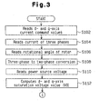
- Fig. 3 is a flowchart of a process performed before the d-axis voltage command value Vd* and the q-axis voltage command value Vq* are obtained.
- the CPU 21 reads the d-axis current command value Id* and the q-axis current command value Iq* from the host controller 10 via the interface circuit I/F 24.
- the CPU 21 reads the U-phase actual current Iu and the W-phase actual current Iw from the current sensors 50u, 50w via the A/D converters 26, 27, respectively, and computes the V-phase actual current Iv.
- step S106 the CPU 21 reads the rotational angle of the rotor from the encoder 50e via the interface circuit I/F 29.
- step S108 the CPU 21 performs a three-phase to two-phase conversion on the U-phase actual current Iu, the V-phase actual current Iv, and the W-phase actual current Iw based on the rotational angle of the rotor to obtain the d-axis actual current Id and the q-axis actual current Iq.
- step S110 the CPU 21 reads the power source voltage Vb from the voltage sensor 40v via the A/D converter 28.
- step S112 the CPU 21 computes the maximum value (hereinafter, referred to as the accumulated maximum value VO) of voltage that can be output from the inverter circuit 30 in the d-axis and q-axis directions of the motor based on the power source voltage Vb.
- the accumulated maximum value VO corresponds to a voltage limit value.
- VO Vb/2 ⁇ (3/2) 1 ⁇ 2 ⁇ k
- k represents the maximum voltage utilization factor of the inverter circuit 30 and is a constant number indicating the utilization factor corresponding to the limit of the duty of the inverter circuit 30.
- the power source voltage Vb and the utilization factor k correspond to physical quantities associated with the inverter circuit 30.
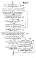
- Fig. 4 is a flowchart of a routine for computing the voltage command value of the q-axis.
- the CPU 21 computes a q-axis current deviation ⁇ Iq using the following equation (2).
- ⁇ Iq Iq* - Iq
- step S204 the CPU 21 determines whether the q-axis voltage is unsaturated on a positive coordinate and the q-axis current deviation ⁇ Iq is a positive value, or the q-axis voltage is unsaturated on a negative coordinate and the q-axis current deviation ⁇ Iq is a negative value. If the decision outcome of step S204 is positive, the CPU 21 performs steps S206 to S210. If the decision outcome of step S204 is negative, the CPU 21 skips steps S206 to S210 and proceeds to step S212. Whether the q-axis voltages is saturated on the positive coordinate and the negative coordinate is determined in accordance with a q-axis voltage positive saturation flag and a q-axis voltage negative saturation flag set in step S218 or S224.
- step S206 the CPU 21 computes a q-axis current deviation accumulated value ⁇ Iq (present value) using the following equation.
- ⁇ Iq (present value) ⁇ Iq (previous value) + ⁇ Iq ⁇ Giq ⁇ T
- sign is a function for performing a sign judgment
- sign( ⁇ Iq) represents "+1" or "-1” in accordance with the judgment result.
- step S212 the CPU 21 computes the q-axis voltage command value Vq* using the following equation (5).
- Vq* ⁇ Iq ⁇ Gpq + ⁇ Iq
- Gpq represents a q-axis current deviation proportional gain.
- the CPU 21 uses the previous value (the value computed in the previous control cycle) of the q-axis current deviation accumulated value ⁇ Iq.
- step S214 the CPU 21 clears the q-axis voltage positive saturation flag and the q-axis voltage negative saturation flag.
- step S216 the CPU 21 determines whether the q-axis voltage command value Vq* computed in step S212 is in positive voltage saturation, that is, whether the q-axis voltage command value Vq* is greater than the accumulated maximum value VO (Vq*>VO). If the decision outcome of step S216 is positive, the CPU 21 performs steps S218 and S220. If the decision outcome of step S216 is negative, the CPU 21 proceeds to step S222.
- step S2108 the CPU 21 sets the q-axis voltage positive saturation flag.
- the q-axis voltage positive saturation flag is referenced in step S204 of the subsequent control cycle.
- step S208 and S210 the absolute value of the q-axis current deviation accumulated value ⁇ Iq is restricted to be less than or equal to the accumulated maximum value VO.
- the absolute value of the q-axis voltage command value Vq* might exceeds the accumulated maximum value VO.
- step S220 is prevents the absolute value of the q-axis voltage command value Vq* from exceeding the accumulated maximum value VO.
- step S222 the CPU 21 determines whether the q-axis voltage command value is in negative voltage saturation, that is, whether the q-axis voltage command value Vq* is smaller than the negative accumulated maximum value VO (Vq* ⁇ -VO). If the decision outcome of step S222 is positive, the CPU 21 performs steps S224 and S226.
- step S224 the CPU sets the q-axis voltage negative saturation flag. The q-axis voltage negative saturation flag is referenced in step S204 of the subsequent control cycle in the same manner as the q-axis voltage positive saturation flag.
- step S222 If the decision outcome of step S222 is negative, the CPU 21 proceeds to step S302.
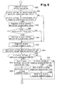
- the CPU 21 executes the routine of the flowchart in Fig. 5, which is a flowchart for computing the d-axis voltage command value Vd*. Since the d-axis voltage command value Vd* is obtained in the same manner as the q-axis voltage command value Vq*, the detailed explanations are omitted.
- ⁇ Id represents a d-axis current deviation and ⁇ Id represents a d-axis current deviation accumulated value.
- Fig. 6 is a flowchart showing a routine for calculating the switching control signals PWMu, PWMv, and PWMw to be sent to the inverter circuit 30 based on the q-axis voltage command value Vq* and the d-axis voltage command value Vd* by a known procedure.
- step S502 the q-axis voltage command value Vq* and the d-axis voltage command value Vd* are subjected to the two-phase to three-phase conversion to obtain the U-phase voltage command value Vu*, the V-phase voltage command value Vv*, and the W-phase voltage command value Vw*.
- step S504 the voltage command values Vu*, Vv*, and Vw* are subjected to PWM conversion to obtain the switching control signals PWMu, PWMv, and PWMw.
- step S506 the switching control signals PWMu, PWMv, and PWMw are sent to the inverter circuit 30 to drive the inverter circuit 30.
- the inverter circuit 30 is driven in accordance with the d-axis current command value Id* and the q-axis current command value Iq* from the host controller 10. Accordingly, the PWM controlled pulse voltage (PWM signal) is supplied to the motor 50.
- the CPU 21 corresponds to voltage limit value setting means, voltage command value computing means, and voltage saturation judging means.
- the process performed by the voltage limit value setting means corresponds to step S112 in Fig. 3.
- the process performed by the voltage command value computing means corresponds to steps S202 to S212 in Fig. 4 and steps S302 to S312 in Fig. 5.
- the CPU 21 also corresponds to the voltage saturation judging means.
- the process performed by the voltage saturation judging means corresponds to steps S214 to S218 and steps S222 to S224 in Fig. 4 and steps S314 to S318 and steps S322 to S324 in Fig. 5.
- control apparatus according to the first embodiment provides the following advantages.
- the advantage (1) is easily achieved.
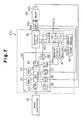
- the second embodiment has the same structure as the first embodiment except that the second embodiment includes a booster circuit 41 and a booster circuit control section 42.
- the booster circuit 41 boosts the power source voltage output from the direct-current power source 40, and then outputs the boosted voltage to the inverter circuit 30.
- the booster circuit control section 42 controls the booster circuit 41.
- the booster circuit 41 and the booster circuit control section 42 will only be described below. Like or the same reference numerals are given to the components that are like or the same as the corresponding components of the first embodiment and detailed explanations are omitted.
- the booster circuit 41 is located between the direct-current power source 40 and the inverter circuit 30.
- the booster circuit 41 is provided with the booster circuit control section 42, which controls the booster circuit 41.
- the booster circuit control section 42 is connected to the CPU 21 via the interface circuit I/F 25a of the control unit 20.
- the booster circuit 41 boosts the voltage output from the direct-current power source 40, and outputs the boosted voltage to the inverter circuit 30.
- the booster circuit 41 is formed by a coil L1, a field effect transistor FET1, a diode D1, and a capacitor C1.
- the booster circuit control section 42 controls on and off of the field effect transistor FET1. Changing the on-time and off-time of the field effect transistor FET1 varies the power source voltage Vb.
- the booster circuit control section 42 adjusts the on-time and off-time of the field effect transistor FET1 in accordance with the instruction from the CPU 21. In other words, the power source voltage Vb that corresponds to the instruction of the CPU 21 is output from the booster circuit 41 to the inverter circuit 30.
- the voltage output from the direct-current power source 40 is sufficient for the load required on the motor 50, there is no problem even in the case with the first embodiment.
- a battery (DC12V/DC24V) of a vehicle is used as the direct-current power source 40 to drive the motor 50 for assisting a power steering of the vehicle
- the voltage supplied to the motor 50 is insufficient and current cannot be supplied to the motor 50. Therefore, necessary motor output (torque and number of rotations) cannot be obtained.
- the number of turns of the motor coil needs to be increased to guarantee the necessary motor output. This undesirably increases the weight and the cost of the motor 5.
- the second embodiment solves this problem by boosting the power source voltage Vb supplied to the inverter circuit 30 by the booster circuit 41 so that the voltage supplied to the motor 50 is increased.
- the CPU 21 instructs the booster 41 to boost the power source voltage Vb to a value corresponding to the load amount on the motor 50. Accordingly, the motor 50 provides the necessary motor output.
- a target value of the output voltage of the booster circuit 41 may be obtained with reference to a table, which is made by calculating the voltage value required for each stage of the load amount on the motor 50 and stored, for example, in the ROM 22.
- the target value may also be computed in every control cycle based on the load amount on the motor 50.
- the load amount on the motor 50 is substantially proportional to the rate of the on-time (positive voltage output time) of the switching element of the inverter circuit 30 in one control cycle, the load amount may be estimated based on this rate to obtain the target value of the output voltage of the booster circuit 41.
- the load amount of the motor 50 can be detected in accordance with the U, V, and W-phase actual current values, or the d-axis actual current Id and the q-axis actual current Iq.
- the booster circuit 41 does not boost the power source voltage Vb. Accordingly, the motor 50 is controlled with high accuracy. In other words, when the load on the motor 50 is small with respect to the power source voltage Vb, the switching frequency of the switching element of the inverter circuit 30 is decreased. This increases the influence of a higher harmonic on the current supplied to the coil of each phase of the motor 50. As a result, the current waveform of the motor coil does not describe a sinusoidal pattern, and the motor 50 cannot be controlled with high accuracy. In this case, the booster circuit 41 is kept from boosting the power source voltage Vb, and the switching element of the inverter circuit 30 is switched at an appropriate frequency so that the motor 50 is controlled with high accuracy.
- the second embodiment provides the following advantage in addition to the advantages (1) to (3) of the first embodiment.
- the booster circuit 41 boosts the output voltage of the direct-current power source 40 before outputting the voltage to the inverter circuit 30.
- the motor 50 gives the motor output that is greater than the motor output obtained when the output voltage from the direct-current power source 40 is sent to the inverter circuit 30 without boosting.
- the motor 50 is controlled with high accuracy.
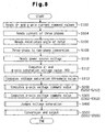
- Figs. 8 and 9 are flowcharts of routines executed by the CPU 21 of the third embodiment.
- the routines are executed once every predetermined control cycle.
- steps S102 to S112, S202 to S212, S302 to S312, and S502 to S506 are the same as those steps in the flowcharts of the first embodiment. Therefore, the same step numbers are given and detailed explanations are omitted.
- Steps S202 to S212 are referred to as a q-axis voltage command value computing routine S200 and steps S302 to 312 are referred to as a d-axis voltage command value computing routine S300.
- Steps S502 to S506 are a sub-routine of a conversion and output routine S500.
- Step S113 executed after step S112 is a process for computing a voltage saturation threshold value.
- the CPU 21 computes the voltage saturation threshold value Vmax in accordance with the following equation (6).
- k is a maximum voltage utilization factor of the inverter circuit 30 and is a constant number indicating the utilization factor corresponding to the limit of the duty of the inverter circuit 30.
- the voltage saturation threshold value Vmax corresponds to a voltage limit value and is the maximum value of the phase voltage that can be output from the inverter circuit 30.
- the power source voltage Vb and the utilization factor k correspond to physical quantities associated with the inverter circuit 30.
- step S113 the CPU 21 executes the q-axis voltage command value computing routine of step S200.
- step S200 the CPU 21 executes the d-axis voltage command value computing routine of step S300.
- step S300 the CPU 21 executes a voltage saturation judging routine of step S400.
- Fig. 9 shows a flowchart of the voltage saturation judging routine of step S400.
- step S402 the CPU 21 clears the q-axis voltage positive saturation flag, the q-axis voltage negative saturation flag, the d-axis voltage positive saturation flag, and the d-axis voltage negative saturation flag.
- step S404 the CPU 21 determines whether the voltage saturation is caused. More specifically, the CPU 21 determines whether a value obtained by combining the vectors of the q-axis voltage command value Vq* and the d-axis voltage command value Vd* satisfies the following conditions. (2/3) 1 ⁇ 2 ⁇ (Vd* ⁇ 2 + Vq* ⁇ 2) 1 ⁇ 2 ⁇ Vmax (voltage saturation threshold value)
- Vu* (2/3) 1 ⁇ 2 ⁇ ⁇ Vd* ⁇ cos ⁇ - Vq* ⁇ sin ⁇
- Vv* (2/3) 1 ⁇ 2 ⁇ ⁇ Vd* ⁇ cos( ⁇ -120°) - Vq* ⁇ sin( ⁇ -120°) ⁇
- Vw* (2/3) 1 ⁇ 2 ⁇ ⁇ Vd* ⁇ cos( ⁇ -240°) - Vq* ⁇ sin( ⁇ -240°) ⁇
- the inverter circuit 30 can only output the voltage in the following range. (-Vb/2) ⁇ ⁇ /100 to (Vb/2) ⁇ ⁇ /100
- phase voltage command value needs to satisfy the following inequality. (2/3) 1 ⁇ 2 ⁇ (Vd* ⁇ 2 + Vq* ⁇ 2) 1 ⁇ 2 ⁇ (Vb/2) ⁇ ⁇ /100
- Vmax voltage saturation threshold value
- Fig. 10 is a diagram showing the phase voltage.
- Fig. 10 shows a phase voltage waveform when voltage saturation is caused and the peak is clamped. Lines U, V, and W each represent the voltage waveform of the corresponding phase.
- step S404 If it is determined that the value obtained by combining the vectors of the q-axis voltage command value Vq* and the d-axis voltage command value Vd* satisfies the equation (7), that is, if the decision outcome of step S404 is positive, the CPU 21 proceeds to step S406. If it is determined that the decision outcome of step S404 is negative, the CPU 21 terminates the routine and proceeds to step S500.
- step S406 the CPU 21 determines whether the sign of the d-axis voltage command value Vd* is positive. If the sign is positive, the CPU 21 proceeds to step S408 and then to S412. In steps S408 and S410, the CPU 21 sets the d-axis voltage positive saturation flag and the d-axis voltage negative saturation flag, respectively. The d-axis voltage positive saturation flag and the d-axis voltage negative saturation flag are referenced in step S304.
- step S412 the CPU 21 determines whether the sign of the q-axis voltage command value Vq* is positive. If the sign is positive, the CPU 21 proceeds to step S414 and then to S418. In steps S414 and S416, the CPU 21 sets the q-axis voltage positive saturation flag and the q-axis voltage negative saturation flag, respectively. The q-axis voltage positive saturation flag and the q-axis voltage negative saturation flag are referenced in step S204.
- step S4108 the CPU 21 adjusts, or corrects, the d-axis voltage command value Vd* and the q-axis voltage command value Vq* such that the equation (7) is satisfied. More specifically, the correcting process includes correcting only the d-axis voltage command value Vd*, correcting only the q-axis voltage command value Vq*, and correcting both the d-axis voltage command value Vd* and the q-axis voltage command value Vq*. In step S418, the CPU 21 performs one of the correcting processes.
- the process 1) for correcting only the d-axis voltage command value Vd* places emphasis on the torque.
- the process 2) for correcting only the q-axis voltage command value Vq* places emphasis on the speed.
- the process 3) for correcting both the d-axis voltage command value Vd* and the q-axis voltage command value Vq* keeps balance between the torque and the speed.
- the process 3) for correcting both the d-axis voltage command value Vd* and the q-axis voltage command value Vq* is executed.
- step S4108 the CPU 21 proceeds to step S500 in which the conversion and output routine is executed. Since the equation (7) is satisfied after the correction process in step S418, the value obtained by combining the vectors of the d-axis voltage command value Vd* and the q-axis voltage command value Vq* does not exceed the range of the voltage that can be output by the inverter circuit 30.
- the CPU 21 corresponds to the voltage limit value setting means, the voltage command value computing means, the voltage saturation judging means, and correction means.
- the process of step S113 in Fig. 8 corresponds to the process of the voltage limit value setting means.
- the process of steps S202 to S212 and S302 to S312 in Fig. 8 correspond to the process of the voltage command value computing means.
- the process of steps S402 to S416 in Fig. 9 corresponds to the process of the voltage saturation judging means.
- the process of step S418 corresponds to the process of the correction means.
- the third embodiment provides the following advantages in addition to the advantages (1) and (3) of the first embodiment.
- the state shown in Fig. 11(b) can be caused.
- the q-axis voltage command value Vq and the d-axis voltage command value Vd are within the accumulated maximum value VO.
- the value obtained by combining the vectors exceeds the voltage saturation threshold value Vmax.
- the peak of the waveform of each phase voltage is saturated and clamped when two-phase to three-phase conversion is performed. This hinders proper sinusoidal power supply and generates noise.
- the value obtained by combining the vectors is adjusted not to exceed the voltage saturation threshold value Vmax. This enables the sinusoidal power supply and reduces generation of torque ripple, vibration, noise, and the like.
- the q-axis voltage command value Vq and the d-axis voltage command value Vd are within the accumulated maximum value VO and the value obtained by combining the vectors of the voltage command values of both axes is within the voltage saturation threshold value Vmax.
Landscapes
- Engineering & Computer Science (AREA)
- Power Engineering (AREA)
- Control Of Ac Motors In General (AREA)
Abstract
Description

Claims (20)
- A motor control apparatus comprising: computing means (21), which receives a current command value in every control cycle, computes a current deviation accumulated value by accumulating the current deviation between the current command value and an actual current value that flows through a coil of a motor (50), and computes a voltage command value in accordance with at least the current deviation accumulated value; a direct-current power source (40), which outputs a direct-current power source voltage; an inverter circuit (30), which outputs a pulse voltage generated by switching the power source voltage by a switching element to the motor; and control means (20), which controls the switching timing of the switching element based on the voltage command value, the motor control apparatus being characterized by:wherein, when the judging means determines that the voltage command value is saturated, the computing means (21) restricts the accumulation of the current deviation.judging means (21), which judges whether the voltage command value computed by the computing means (21) exceeds a range of the voltage that can be output from the inverter circuit (30), and is saturated , and
- The motor control apparatus according to claim 1 characterized by:wherein the inverter circuit (30) supplies the motor with the pulse voltage, which is generated by switching the output voltage of the booster circuit (41) with the switching element.a booster circuit (41), which boosts a power source voltage output from the direct-current power source (40) and outputs the boosted power source voltage to the inverter circuit (30); anda booster circuit control means (42), which controls the output voltage of the booster circuit (41) in accordance with a load amount of the motor (50), and
- The motor control apparatus according to claim 1 or 2 characterized by:wherein the judging means (21) compares a value based on the voltage command value with the set voltage limit value in every control cycle, and judges that the voltage command value is saturated if the value based on the voltage command value is greater than the voltage limit value, andsetting means (21), which sets a voltage limit value based on a physical quantity associated with the inverter circuit (30) for judging saturation of the voltage command value,
wherein, when the judging means (21) judges that the voltage command value is saturated, the computing means (21) suppresses the current deviation accumulated value from increasing by stopping the accumulation of the current deviation in the subsequent control cycle. - The motor control apparatus according to claim 3,
characterized in that the current command value, the actual current value, the current deviation, the current deviation accumulated value, and the voltage command value are related to two orthogonal axes of a rotational coordinate system associated with a rotor of the motor,
wherein the voltage limit value is the maximum value of the voltage that can be output from the inverter circuit (30) to the motor (50) in the axial directions of the two orthogonal axes, and
wherein the judging means (21) compares the voltage command values of the two axes of the rotational coordinate system with the voltage limit value, and if either of the voltage command values is greater than the voltage limit value, the judging means (21) judges that the voltage command value is saturated. - The motor control apparatus according to claim 3,
characterized in that the current command value, the actual current value, the current deviation, the current deviation accumulated value, and the voltage command value are related to two orthogonal axes of a rotational coordinate system associated with a rotor of the motor,
wherein the voltage limit value is the maximum value of the phase voltage that can be output from the inverter circuit (30), and
wherein the judging means (21) compares a value obtained by combining vectors of the voltage command values of the two axes of the rotational coordinate system with the voltage limit value, and if the value obtained by combining the vectors is greater than the voltage limit value, the judging means (21) judges that the voltage command value is saturated. - The motor control apparatus according to claim 4 or 5,
characterized in that, when the judging means (21) judges that the voltage command value is saturated and the current deviation accumulated value of each axis and the current deviation have the same sign, the computing means (21) stops accumulating the current deviation in the subsequent control cycle to suppress the current deviation accumulated value from increasing. - The motor control apparatus according to claim 6, characterized by correcting means (21), wherein, when the judging means (21) judges that the voltage command value is saturated, the correcting means (21) corrects the voltage command value related to at least one of the axes such that the value obtained by combining the vectors of the voltage command values of the two axes computed by the computing means (21) does not exceed the range of the voltage that can be output from the inverter circuit.
- The motor control apparatus according to claim 7,
characterized in that the two axes are a d-axis and a q-axis,
wherein the correcting means (21) corrects the voltage command value related to the d-axis for performing the correction where emphasis is placed on the torque. - The motor control apparatus according to claim 7,
characterized in that the two axes are a d-axis and a q-axis,
wherein the correcting means (21) corrects the voltage command value related to the q-axis for performing the correction where emphasis is placed on the speed. - The motor control apparatus according to claim 7, characterized in that the two axes are a d-axis and a q-axis,
wherein the correcting means (21) corrects the voltage command values related to the d-axis and the q-axis. - A method for controlling a motor, wherein a current command value is received in every control cycle, and a current deviation accumulated value is computed by accumulating the current deviation between the current command value and an actual current value that flows through a coil of the motor (50), and a voltage command value is computed in accordance with at least the current deviation accumulated value, and a pulse voltage, which is generated by switching a direct-current power source voltage by a switching element of an inverter circuit (30) based on the computed voltage command value, is output to the motor (50), the method being characterized by:judging whether the computed voltage command value causes a voltage saturation exceeding a range of the voltage that can be output from the inverter circuit (30); andrestricting the accumulation of the current deviation of the current deviation accumulated value when the voltage command value is judged to be saturated.
- The method according to claim 11, characterized by boosting the power source voltage supplied to the inverter circuit (30) in accordance with the load amount on the motor (50).
- The method according to claim 11 or 12 characterized by:setting a voltage limit value based on a physical quantity associated with the inverter circuit (30) for judging saturation of the voltage command value; andcomparing the value based on the voltage command value with the set voltage limit value in every control cycle, judging that the voltage command value is saturated if the value based on the voltage command value is greater than the voltage limit value, and stopping the accumulation of the current deviation that increases the current deviation accumulated value in the subsequent control cycle.
- The method according to claim 13,
characterized in that the current command value, the actual current value, the current deviation, the current deviation accumulated value, and the voltage command value are related to two orthogonal axes of a rotational coordinate system associated with a rotor of the motor (50),
wherein the voltage limit value is the maximum value of the voltage that can be output from the inverter circuit (30) to the motor (50) in the axial directions of the two orthogonal axes, and
wherein, when judging whether the voltage command value is saturated, the voltage command values of the two axes of the rotational coordinate system are compared with the voltage limit value, and if either of the voltage command values is greater than the voltage limit value, the voltage command value is judged to be saturated. - The method according to claim 13,
characterized in that the current command value, the actual current value, the current deviation, the current deviation accumulated value, and the voltage command value are related to two orthogonal axes of a rotational coordinate system associated with a rotor of the motor (50),
wherein the voltage limit value is the maximum value of the phase voltage that can be output from the inverter circuit (30), and
wherein, when judging whether the voltage command value is saturated, a value obtained by combining vectors of the voltage command values of the two axes of the rotational coordinate system is compared with the voltage limit value, and if the value obtained by combining the vectors of the voltage command values is greater than the voltage limit value, the voltage command value is judged to be saturated. - The method according to claim 14 or 15,
characterized in that, when computing the voltage command value, if the voltage command value is judged to be saturated and the current deviation accumulated value of each axis and the current deviation have the same sign, the accumulation of the current deviation in the subsequent control cycle is stopped to suppress the current deviation accumulated value of the two axes from increasing. - The method according to claim 16,
characterized in that, when the voltage command value is judged to be saturated, the voltage command value related to at least one of the axes is corrected such that the computed value obtained by combining the vectors of the voltage command values of the two axes does not exceed the range of the voltage that can be output from the inverter circuit (30). - The method according to claim 17,
characterized in that the two axes are a d-axis and a q-axis, and the correction is a correction of the voltage command value related to the d-axis for performing the correction where emphasis is placed on the torque. - The method according to claim 17,
characterized in that the two axes are a d-axis and a q-axis, and the correction is a correction of the voltage command value related to the q-axis for performing the correction where emphasis is placed on the speed. - The method according to claim 17,
characterized in that the two axes are a d-axis and a q-axis, and the correction is a correction of the voltage command values related to the d-axis and the q-axis.
Applications Claiming Priority (2)
| Application Number | Priority Date | Filing Date | Title |
|---|---|---|---|
| JP2003144321A JP2004229487A (en) | 2002-11-29 | 2003-05-22 | Motor control device and method for controlling motor |
| JP2003144321 | 2003-05-22 |
Publications (2)
| Publication Number | Publication Date |
|---|---|
| EP1480330A2 true EP1480330A2 (en) | 2004-11-24 |
| EP1480330A3 EP1480330A3 (en) | 2007-09-26 |
Family
ID=33095453
Family Applications (1)
| Application Number | Title | Priority Date | Filing Date |
|---|---|---|---|
| EP04012074A Withdrawn EP1480330A3 (en) | 2003-05-22 | 2004-05-21 | Apparatus and method for controlling a motor |
Country Status (2)
| Country | Link |
|---|---|
| US (1) | US7102305B2 (en) |
| EP (1) | EP1480330A3 (en) |
Cited By (2)
| Publication number | Priority date | Publication date | Assignee | Title |
|---|---|---|---|---|
| EP1703628A1 (en) * | 2005-03-15 | 2006-09-20 | Schneider Toshiba Inverter Europe SAS | Method and system for controlling an electric motor in the event of flux reduction |
| FR3012270A1 (en) * | 2013-10-17 | 2015-04-24 | Renault Sa | METHOD AND SYSTEM FOR CONTROLLING AN ELECTRIC MACHINE OF A MOTOR VEHICLE |
Families Citing this family (28)
| Publication number | Priority date | Publication date | Assignee | Title |
|---|---|---|---|---|
| US7102305B2 (en) * | 2003-05-22 | 2006-09-05 | Toyoda Koki Kabushiki Kaisha | Apparatus and method for controlling motor |
| JP4422567B2 (en) * | 2004-06-30 | 2010-02-24 | 株式会社日立製作所 | Motor drive device, electric actuator, and electric power steering device |
| JP2006094594A (en) * | 2004-09-22 | 2006-04-06 | Nsk Ltd | In-vehicle motor control device, electric power steering device and electric brake device using the same |
| JP2006238631A (en) * | 2005-02-25 | 2006-09-07 | Mitsubishi Heavy Ind Ltd | MOTOR CONTROLLING METHOD USING Id/Iq TABLE |
| JP4706324B2 (en) * | 2005-05-10 | 2011-06-22 | トヨタ自動車株式会社 | Control device for motor drive system |
| JP4730073B2 (en) * | 2005-12-02 | 2011-07-20 | 株式会社日立製作所 | Permanent magnet synchronous motor vector controller, inverter module, and permanent magnet synchronous motor motor constant display system |
| JP4899611B2 (en) * | 2006-04-24 | 2012-03-21 | 株式会社ジェイテクト | Electric power steering device |
| JP4228237B2 (en) * | 2006-06-06 | 2009-02-25 | トヨタ自動車株式会社 | Electric power steering device |
| WO2009001468A1 (en) * | 2007-06-28 | 2008-12-31 | Mitsubishi Electric Corporation | Power converter |
| US20090051414A1 (en) * | 2007-08-20 | 2009-02-26 | Per Olaf Pahr | Dual conversion rate voltage booster apparatus and method |
| JP4452735B2 (en) * | 2007-09-05 | 2010-04-21 | 本田技研工業株式会社 | Boost converter control device and control method |
| CN102196938B (en) * | 2008-10-23 | 2014-04-23 | 三菱电机株式会社 | Tram propulsion control device |
| JP4728406B2 (en) * | 2009-01-07 | 2011-07-20 | 本田技研工業株式会社 | Electric power steering device |
| US8508166B2 (en) | 2009-08-10 | 2013-08-13 | Emerson Climate Technologies, Inc. | Power factor correction with variable bus voltage |
| US8264192B2 (en) | 2009-08-10 | 2012-09-11 | Emerson Climate Technologies, Inc. | Controller and method for transitioning between control angles |
| US8698433B2 (en) * | 2009-08-10 | 2014-04-15 | Emerson Climate Technologies, Inc. | Controller and method for minimizing phase advance current |
| US9634593B2 (en) | 2012-04-26 | 2017-04-25 | Emerson Climate Technologies, Inc. | System and method for permanent magnet motor control |
| EP2883302B1 (en) | 2012-08-10 | 2020-09-30 | Emerson Climate Technologies, Inc. | Motor drive control using pulse-width modulation pulse skipping |
| JP5811363B2 (en) * | 2013-03-13 | 2015-11-11 | 株式会社デンソー | Rotating electrical machine control device and electric power steering device using the same |
| JP5620535B2 (en) * | 2013-03-19 | 2014-11-05 | ファナック株式会社 | Motor control system that detects voltage saturation |
| JP5890465B2 (en) * | 2014-05-08 | 2016-03-22 | ファナック株式会社 | Motor control device for detecting motor power line disconnection or power element abnormality of motor power converter |
| JP5887389B1 (en) * | 2014-08-12 | 2016-03-16 | ファナック株式会社 | PWM rectifier for motor drive connected to power storage device |
| JP6260502B2 (en) | 2014-09-16 | 2018-01-17 | 株式会社デンソー | Motor control device |
| US9854190B2 (en) | 2015-03-24 | 2017-12-26 | Semiconductor Components Industries, Llc | Imaging systems and methods for transient signal integrity verification |
| JP6233428B2 (en) * | 2016-02-12 | 2017-11-22 | 株式会社安川電機 | Motor control device and motor control method |
| US10135368B2 (en) * | 2016-10-01 | 2018-11-20 | Steering Solutions Ip Holding Corporation | Torque ripple cancellation algorithm involving supply voltage limit constraint |
| CN109474178B (en) * | 2017-09-07 | 2020-02-07 | 台达电子企业管理(上海)有限公司 | Semiconductor chip power supply system |
| JP7261050B2 (en) | 2019-03-20 | 2023-04-19 | 日立Astemo株式会社 | MOTOR CONTROL DEVICE AND MOTOR CONTROL METHOD |
Family Cites Families (36)
| Publication number | Priority date | Publication date | Assignee | Title |
|---|---|---|---|---|
| JPH0984400A (en) * | 1995-09-14 | 1997-03-28 | Fanuc Ltd | Method for controlling current of servomotor |
| JP3683313B2 (en) * | 1995-09-22 | 2005-08-17 | ファナック株式会社 | Servo motor current control method |
| JP3709239B2 (en) * | 1996-04-26 | 2005-10-26 | ファナック株式会社 | Magnetic saturation correction method for AC servo motor |
| JP3746334B2 (en) * | 1996-08-22 | 2006-02-15 | トヨタ自動車株式会社 | Permanent magnet type synchronous motor drive control apparatus and method |
| JP3121561B2 (en) * | 1997-04-21 | 2001-01-09 | ファナック株式会社 | Injection molding machine |
| JP2000032799A (en) * | 1998-07-07 | 2000-01-28 | Hitachi Ltd | Control device and control method for rotating electric machine |
| US6281656B1 (en) * | 1998-09-30 | 2001-08-28 | Hitachi, Ltd. | Synchronous motor control device electric motor vehicle control device and method of controlling synchronous motor |
| JP3729682B2 (en) * | 1999-06-15 | 2005-12-21 | 三菱電機株式会社 | Vector control equipment |
| JP3661572B2 (en) * | 2000-07-18 | 2005-06-15 | 日産自動車株式会社 | Inverter current sensor diagnostic device |
| US6611127B2 (en) * | 2000-08-07 | 2003-08-26 | Nissan Motor Co., Ltd. | Drive circuit for motor/generator |
| JP3721116B2 (en) * | 2000-11-14 | 2005-11-30 | 株式会社豊田中央研究所 | DRIVE DEVICE, POWER OUTPUT DEVICE, AND CONTROL METHOD THEREOF |
| EP1211798B1 (en) * | 2000-11-22 | 2018-01-10 | Nissan Motor Co., Ltd. | Motor control apparatus and motor control method |
| JP3634270B2 (en) * | 2001-02-02 | 2005-03-30 | 株式会社豊田中央研究所 | Motor drive circuit |
| JP4013483B2 (en) * | 2001-02-13 | 2007-11-28 | 株式会社日立製作所 | Power converter control device |
| DE60224021T2 (en) * | 2001-03-02 | 2008-12-04 | Matsushita Electric Industrial Co., Ltd., Kadoma | Control unit for an electric motor |
| JP3695342B2 (en) * | 2001-04-11 | 2005-09-14 | 株式会社日立製作所 | Electric motor control device |
| JP2002335699A (en) * | 2001-05-09 | 2002-11-22 | Hitachi Ltd | Control device for AC motor |
| JP3627683B2 (en) * | 2001-06-29 | 2005-03-09 | 日産自動車株式会社 | Motor control device |
| CN1212701C (en) * | 2001-07-13 | 2005-07-27 | 三菱电机株式会社 | AC motor speed control device |
| JP3918148B2 (en) * | 2001-07-24 | 2007-05-23 | 株式会社日立製作所 | Inverter device |
| JP3480843B2 (en) * | 2001-09-04 | 2003-12-22 | 三菱電機株式会社 | Electric power steering control device and control method |
| JP3582505B2 (en) * | 2001-09-10 | 2004-10-27 | 日産自動車株式会社 | Motor control device |
| JP3722048B2 (en) * | 2001-11-15 | 2005-11-30 | 日産自動車株式会社 | Motor control device |
| JP3685138B2 (en) * | 2002-02-18 | 2005-08-17 | 日産自動車株式会社 | Motor control device |
| JP4357967B2 (en) * | 2002-03-22 | 2009-11-04 | パナソニック株式会社 | Control device for synchronous reluctance motor |
| JP3914108B2 (en) * | 2002-07-15 | 2007-05-16 | 本田技研工業株式会社 | DC brushless motor control device |
| JP3695436B2 (en) * | 2002-09-18 | 2005-09-14 | 株式会社日立製作所 | Position sensorless motor control method and apparatus |
| US6963182B2 (en) * | 2002-11-29 | 2005-11-08 | Toyoda Koki Kabushiki Kaisha | Motor control device and motor control method |
| US7102305B2 (en) * | 2003-05-22 | 2006-09-05 | Toyoda Koki Kabushiki Kaisha | Apparatus and method for controlling motor |
| JP4294380B2 (en) * | 2003-06-04 | 2009-07-08 | 株式会社ジェイテクト | Vehicle steering system |
| US6831440B1 (en) * | 2003-06-30 | 2004-12-14 | Rockwell Automation Technologies, Inc. | Flux position identifier using high frequency injection |
| JP4030528B2 (en) * | 2004-06-16 | 2008-01-09 | 三菱電機株式会社 | Method for adjusting drive current offset in electric power steering control device |
| JP4007344B2 (en) * | 2004-06-29 | 2007-11-14 | アイシン・エィ・ダブリュ株式会社 | Electric drive control device, electric drive control method, and program |
| JP4007345B2 (en) * | 2004-06-29 | 2007-11-14 | アイシン・エィ・ダブリュ株式会社 | Electric drive control device, electric drive control method, and program |
| JP4319112B2 (en) * | 2004-08-27 | 2009-08-26 | 三菱電機株式会社 | Electric power steering device |
| JP4556572B2 (en) * | 2004-09-09 | 2010-10-06 | アイシン・エィ・ダブリュ株式会社 | Electric drive control device, electric drive control method, and program |
-
2004
- 2004-05-21 US US10/849,816 patent/US7102305B2/en not_active Expired - Fee Related
- 2004-05-21 EP EP04012074A patent/EP1480330A3/en not_active Withdrawn
Cited By (4)
| Publication number | Priority date | Publication date | Assignee | Title |
|---|---|---|---|---|
| EP1703628A1 (en) * | 2005-03-15 | 2006-09-20 | Schneider Toshiba Inverter Europe SAS | Method and system for controlling an electric motor in the event of flux reduction |
| FR2883431A1 (en) * | 2005-03-15 | 2006-09-22 | Schneider Toshiba Inverter | METHOD AND SYSTEM FOR CONTROLLING AN ELECTRIC MOTOR IN CASE OF FLOW |
| US7221117B2 (en) | 2005-03-15 | 2007-05-22 | Schneider Toshiba Inverter Europe Sas | Method and system for controlling an electric motor in the event of flux reduction |
| FR3012270A1 (en) * | 2013-10-17 | 2015-04-24 | Renault Sa | METHOD AND SYSTEM FOR CONTROLLING AN ELECTRIC MACHINE OF A MOTOR VEHICLE |
Also Published As
| Publication number | Publication date |
|---|---|
| US20040232865A1 (en) | 2004-11-25 |
| EP1480330A3 (en) | 2007-09-26 |
| US7102305B2 (en) | 2006-09-05 |
Similar Documents
| Publication | Publication Date | Title |
|---|---|---|
| US7102305B2 (en) | Apparatus and method for controlling motor | |
| EP1881596B1 (en) | Motor drive system control device and electric vehicle using the same | |
| KR100986712B1 (en) | Control device and method of motor drive system | |
| US8285451B2 (en) | Method and apparatus for controlling electric power steering system | |
| JP3559258B2 (en) | Steering control device | |
| US7728541B2 (en) | Electric motor drive control method and apparatus | |
| KR101027231B1 (en) | Vector control unit of permanent magnet synchronous motor | |
| JP4353304B2 (en) | Motor drive control device | |
| US6771039B2 (en) | Motor control apparatus and method | |
| US9112436B2 (en) | System for controlling controlled variable of rotary machine | |
| US10333440B2 (en) | Motor control apparatus and electric power steering system | |
| US20100176757A1 (en) | Controller for motor drive control system | |
| JP6428248B2 (en) | Motor control device | |
| JP2009095144A (en) | AC motor control device and AC motor control method | |
| US12278582B2 (en) | Controller for rotary machine | |
| JP5233861B2 (en) | Motor control device | |
| EP2395650B1 (en) | Direct-current to three-phase alternating-current inverter system | |
| JP2004229487A (en) | Motor control device and method for controlling motor | |
| US20200144883A1 (en) | Controller of rotating electric machine | |
| JP7317250B2 (en) | Rotating electric machine control device and electric power steering device | |
| US6963182B2 (en) | Motor control device and motor control method | |
| US12218617B2 (en) | Controller for electric motor | |
| JP2004061217A (en) | Current detection device and method, and motor device | |
| US11323061B2 (en) | AC rotating electric machine control device | |
| US12237784B2 (en) | Motor control device |
Legal Events
| Date | Code | Title | Description |
|---|---|---|---|
| PUAI | Public reference made under article 153(3) epc to a published international application that has entered the european phase |
Free format text: ORIGINAL CODE: 0009012 |
|
| AK | Designated contracting states |
Kind code of ref document: A2 Designated state(s): AT BE BG CH CY CZ DE DK EE ES FI FR GB GR HU IE IT LI LU MC NL PL PT RO SE SI SK TR |
|
| AX | Request for extension of the european patent |
Extension state: AL HR LT LV MK |
|
| RAP1 | Party data changed (applicant data changed or rights of an application transferred) |
Owner name: JTEKT CORPORATION |
|
| RIN1 | Information on inventor provided before grant (corrected) |
Inventor name: SUZUKI, HIROSHI, |
|
| PUAL | Search report despatched |
Free format text: ORIGINAL CODE: 0009013 |
|
| AK | Designated contracting states |
Kind code of ref document: A3 Designated state(s): AT BE BG CH CY CZ DE DK EE ES FI FR GB GR HU IE IT LI LU MC NL PL PT RO SE SI SK TR |
|
| AX | Request for extension of the european patent |
Extension state: AL HR LT LV MK |
|
| 17P | Request for examination filed |
Effective date: 20080325 |
|
| AKX | Designation fees paid |
Designated state(s): DE FR GB |
|
| 17Q | First examination report despatched |
Effective date: 20090825 |
|
| STAA | Information on the status of an ep patent application or granted ep patent |
Free format text: STATUS: THE APPLICATION IS DEEMED TO BE WITHDRAWN |
|
| 18D | Application deemed to be withdrawn |
Effective date: 20100105 |