EP1479998B1 - Improved adjustable holster securement device - Google Patents
Improved adjustable holster securement device Download PDFInfo
- Publication number
- EP1479998B1 EP1479998B1 EP04425353A EP04425353A EP1479998B1 EP 1479998 B1 EP1479998 B1 EP 1479998B1 EP 04425353 A EP04425353 A EP 04425353A EP 04425353 A EP04425353 A EP 04425353A EP 1479998 B1 EP1479998 B1 EP 1479998B1
- Authority
- EP
- European Patent Office
- Prior art keywords
- holster
- seatings
- seating
- loop attachment
- connection plate
- Prior art date
- Legal status (The legal status is an assumption and is not a legal conclusion. Google has not performed a legal analysis and makes no representation as to the accuracy of the status listed.)
- Active
Links
Images
Classifications
-
- F—MECHANICAL ENGINEERING; LIGHTING; HEATING; WEAPONS; BLASTING
- F41—WEAPONS
- F41C—SMALLARMS, e.g. PISTOLS, RIFLES; ACCESSORIES THEREFOR
- F41C33/00—Means for wearing or carrying smallarms
- F41C33/02—Holsters, i.e. cases for pistols having means for being carried or worn, e.g. at the belt or under the arm
- F41C33/04—Special attachments therefor
- F41C33/041—Special attachments therefor for connecting a holster to a belt, webbing or other object
- F41C33/045—Special attachments therefor for connecting a holster to a belt, webbing or other object for connection in more than one rotational position around an axle, e.g. by using a rotatable connection
-
- A—HUMAN NECESSITIES
- A45—HAND OR TRAVELLING ARTICLES
- A45F—TRAVELLING OR CAMP EQUIPMENT: SACKS OR PACKS CARRIED ON THE BODY
- A45F5/00—Holders or carriers for hand articles; Holders or carriers for use while travelling or camping
- A45F5/02—Fastening articles to the garment
-
- A—HUMAN NECESSITIES
- A45—HAND OR TRAVELLING ARTICLES
- A45F—TRAVELLING OR CAMP EQUIPMENT: SACKS OR PACKS CARRIED ON THE BODY
- A45F5/00—Holders or carriers for hand articles; Holders or carriers for use while travelling or camping
- A45F5/02—Fastening articles to the garment
- A45F5/021—Fastening articles to the garment to the belt
-
- A—HUMAN NECESSITIES
- A45—HAND OR TRAVELLING ARTICLES
- A45F—TRAVELLING OR CAMP EQUIPMENT: SACKS OR PACKS CARRIED ON THE BODY
- A45F5/00—Holders or carriers for hand articles; Holders or carriers for use while travelling or camping
- A45F5/02—Fastening articles to the garment
- A45F2005/025—Fastening articles to the garment with a holder or item rotatably connected to the fastening device, e.g. having a rotation axis perpendicular to the garment
- A45F2005/027—Fastening articles to the garment with a holder or item rotatably connected to the fastening device, e.g. having a rotation axis perpendicular to the garment with a horizontal and parallel rotation axis, i.e. the axis being parallel to the surface of the garment
-
- A—HUMAN NECESSITIES
- A45—HAND OR TRAVELLING ARTICLES
- A45F—TRAVELLING OR CAMP EQUIPMENT: SACKS OR PACKS CARRIED ON THE BODY
- A45F2200/00—Details not otherwise provided for in A45F
- A45F2200/05—Holder or carrier for specific articles
- A45F2200/0591—Defense articles, e.g. small arms, handguns, pistols, or the like
Definitions
- the present invention generally relates to the field of professional accessories issued to police officers, military men, armed surveillance services and the like. More particularly, the invention relates to an adjustable holster securement device of an improved type for securing a holster to a user belt and allowing adjustable positioning of the holster to improve its comfort, effectiveness and safety in use.
- a holster securement device of the known type that makes it possible to adjust the inclination of the holster is disclosed in Italian Patent Application No. FI20001A000090 .
- the holster securement device in accordance with this patent application comprises a loop portion engageable with the user's belt, a connection portion inclined with respect to said loop portion and a base extending at the free end of said connection portion and having a disc member to which the holster can be pivotally secured.
- a row of equally spaced pins extends along the edge of the disc member from one of its faces and a tooth may be snap fit engaged in the spaces between any chosen pair of said pins, thus preventing any further possibility of rotation to occur.
- the tooth is connected to a sliding arm and it is possible to disengage the tooth from the pins by pressing the end of the arm to allow the disc member to be freely rotated up to find the desired angular position of the holster.
- the holster securement device in accordance with the cited patent application also permits regulation of the height of the holster, i.e. the distance of the holster from the belt, because the disc member for adjusting the inclination of the holster is fixed to a sliding plate mounted on the base of the holster securement device and capable of being arranged into at least two position in which the holster is at different distances from the belt. In this way the distance of the holster from the belt can be adjusted, but this is obtained by increasing the thickness, and therefore the encumbrance, of the holster securement device.
- the entire holster securement device has to be left attached to the user's belt even after the holster has been removed and this becomes bothersome and uncomfortable due to the encumbrance of the securement device.
- a holster securement device in which a double-jointed connection is provided between the loop attachment and the base to which the holster is secured is disclosed in Italian patent application no. PI2001A000082 .
- This connection is constituted by a substantially double-T shaped joint hinged both to the loop attachment and the base of the holster securement device.
- this adjustment can only be carried out by using a tool to act on the screws that lock the two hinges.
- the regulation is therefore laborious and problematical every time it has to be carried out and an appropriate tool is not available.
- the object of the present invention is to provide an adjustable holster securement device of an improved type by means of which all the aforementioned drawbacks associated with holster securement devices of the known type can be overcome.
- Another object of the present invention is to provide a holster securement device of the aforementioned type in which the adjustment of the distance of the holster from the point of attachment to the belt can be obtained without penalizing the dimensions of the device.
- a further object of the present invention is to provide a holster securement device of the aforementioned type in which the dimension of the portion thereof that remains attached to the belt when the holster containing the weapon is not worn is very low.
- Yet another object of the present invention is to provide a holster securement device of the aforementioned type in which there is provided a system for adjusting the inclination of the holster by means of a locking device that is readily accessible and assures an adequate stability of the chosen position even when the user is bumped.
- the improved adjustable holster securement device in accordance with the present invention comprising an articulated joint to provide a connection between the loop attachment and the holster connection plate, said joint being formed by two opposedly arranged, substantially U-shaped members pivotably engaged in respective seatings, the two pairs of seatings being coaxial and parallel and integral with, respectively, said loop attachment and said connection plate, and comprises also tie-rod means acting parallel to said seatings for connecting the substantially U-shaped members to each other at a variable mutual distance.
- Means for locking the articulated joint operated by the tie-rod means to control the locking or the release of the joint are provided between the substantially U-shaped members and the seatings.
- the seatings are formed in pairs on sleeves extending along the adjacent sides of the loop attachment and the connection plate and each of the substantially U-shaped members has two parallel, spaced apart pins engageable with these seatings.
- the means for locking the articulated joint are provided at the base of the pins and at the ends of the sleeves in the form of toothed portions axially engageable with each other.
- the loop attachment comprises a seating engaging with a bracket extending at right angles from the sleeve arranged along one of its sides.
- the bracket has a flexible tongue with an enlarged end selectively engageable within openings formed along said seating in the longitudinal direction, so that, by engaging the tongue with one or the other of the openings, the height of the holster securement device can be varied.
- the adjustment of the inclination of the holster is obtained by providing the rotatable disc carrying the holster with one or more notches along its edge engageable with a small cylinder integral with the connection plate and constrained to slide in the radial direction with respect to the disc.
- An arm sliding elastically parallel to the sleeve and extending along the side of the plate has a side with two concave portions of different depths.
- the adjustable holster securement device in accordance with the invention is substantially made of three components:
- the seatings provided in the sleeves 4 and 5 form part of the articulated joint 2, which also comprises two substantially U-shaped members, each of which is made up of an end element 6, 7.
- a pair of pins, respectively indicated by 8a,b and 9a,b, extends from end elements 6, 7, each of them being engaged with the seatings of the sleeves 4 and 5 from opposite sides, thus forming an articulated joint with two hinges having parallel axes.
- Frontally toothed gears 6a, b and 7a, b are arranged at the base of pins 8a, b and 9a, b in a coaxial relation with them.
- Gears 6a, b and 7a, b are designed to engage with corresponding frontally toothed gears 4a and 5a at the ends of the sleeve seatings 4 and 5.
- a stem 10 extends from one of the two end elements 6 or 7 and is formed with a threaded end capable of engaging with a corresponding seating, not shown, provided on a locking nut 11 pivotally connected to the other end element 6 or 7 of the articulated joint 2.
- Stem 10 is parallel to the axes of the sleeve seatings 4 and 5 and extends between them.
- locking nut 11 By rotating locking nut 11, it is possible to screw it onto the stem 10, thus making it function as a tie rod that will gradually bring the substantially U-shaped members closer to each other and thus also bring the frontally toothed gears 4a and 5a, formed at the ends of the sleeve seatings 4 and 5, closer to the corresponding frontally toothed gears 6a,b and 7a,b, until they eventually engage with each other and completely lock the articulated joint.
- connection plate 3 it is thus possible to choose the preferred angular orientation for the connection plate 3, and therefore also of the plane in which the holster lies, around the axis of the seatings of the sleeve 5, as well as the preferred angular orientation of the sleeve seatings 5 with respect to the sleeve seating 4, thereby displacing the planes of loop attachment 1 and connection plate 3 with respect to each other.
- the articulated joint 2 can be locked by simply rotating the locking nut 11 as described above.
- the loop attachment 1 comprises a box-shaped body 12 with belt passages 13a and 13b formed along two sides.
- the interior of the box-shaped body 12 defines a seat 14 for a bracket 15 extending radially from the sleeve 4 and slidingly housed within seat 14.
- a flexible tongue 16 is cut from the bracket and is so shaped as to be slightly inclined with respect to the plane of the bracket 15.
- On one face of the box-like body 12 there are provided some axially aligned openings, (three openings and of circular shape in the present embodiment of the invention), while the free end of the tongue 16 has an enlargement 16a of such shape as to snap into a reversible engagement with one of the openings 17, though partially projecting from it.
- connection plate 3 to which the holster is attached is actually formed by two shells 3a and 3b fixable to each other by means of screws 18 to clasp between them the externally projecting edge 19a of a disc-shaped body 19 provided with means for the holster connection (in this specific case through holes 20 for a screw connection).
- a cavity 21 engaging with a small cylinder 22 perpendicular to the shells 3a, 3b and integrally attached to them, though it can slide in the radial direction of the disc-shaped body 19.
- a seating 23 is formed on the inner face of the shell 3a, said seating being delimited by a U-shaped wall 24 within which one end of the small cylinder 22 is arranged.
- the small cylinder 22 is prevented from sliding in the seating 23 by an arm 25 that rests elastically against it.
- the arm 25 extends slidingly between the two shells 3a and 3b and in parallel with the sleeve 5 between the sleeve and the disc-shaped body 19.
- An edge portion 25a of arm 25 is shaped and made concave enough to bear against the small cylinder 22 and thus prevent it from sliding.
- a spring 26 is arranged between the free end of the arm 25 and the edge of the shell 3a to keep the concave portion 25a elastically forced against the small cylinder 22.
- a further and more concave portion 25b is formed adjacent to the concave portion 25a along with the edge of arm 25 in such a way as not to abut against the cylinder 22, which is therefore free to slide.
- the adjustable holster securement device allows all the previously recalled drawbacks associated with holster securement devices of the conventional type to be avoided.
- the fact that the system for regulating the height of the holster securement device is incorporated in the loop attachment not only allows for a significant reduction of the encumbrance of the connection plate 3, but also offers the possibility of minimizing the number of components of the holster securement device that remain attached to the belt in all the conditions in which it is not necessary for the user to carry the weapon with him.
- the bracket 15 can be completely withdrawn from the box-shaped body 12, so that the latter only remains attached to the belt in all these cases.
Abstract
Description
- The present invention generally relates to the field of professional accessories issued to police officers, military men, armed surveillance services and the like. More particularly, the invention relates to an adjustable holster securement device of an improved type for securing a holster to a user belt and allowing adjustable positioning of the holster to improve its comfort, effectiveness and safety in use.
- As is well known, law enforcement personnel generally make use of holsters secured to the belt by means of a loop made of plastic or metallic material or leather. Solutions of this type have proven disadvantageous in that they do not permit an optimal adjustment to the physical conformations of the users and individual holster positioning needs. In particular, it is considered an important feature the possibility to adjust the distance of the holster from the attachment to the belt, the inclination with respect to the vertical of the axis of the holster, the inclination with respect to the vertical of the plane in which the holster lies, and the distance of said plane from the point of attachment to the belt.
- A holster securement device of the known type that makes it possible to adjust the inclination of the holster is disclosed in Italian Patent Application No.
FI20001A000090 - The holster securement device in accordance with the cited patent application also permits regulation of the height of the holster, i.e. the distance of the holster from the belt, because the disc member for adjusting the inclination of the holster is fixed to a sliding plate mounted on the base of the holster securement device and capable of being arranged into at least two position in which the holster is at different distances from the belt. In this way the distance of the holster from the belt can be adjusted, but this is obtained by increasing the thickness, and therefore the encumbrance, of the holster securement device. Furthermore, whenever it is not necessary to carry the weapon, while staying in the office for example, the entire holster securement device has to be left attached to the user's belt even after the holster has been removed and this becomes bothersome and uncomfortable due to the encumbrance of the securement device.
- A holster securement device in which a double-jointed connection is provided between the loop attachment and the base to which the holster is secured is disclosed in
Italian patent application no. PI2001A000082 - The object of the present invention is to provide an adjustable holster securement device of an improved type by means of which all the aforementioned drawbacks associated with holster securement devices of the known type can be overcome.
- More particularly, it is an object of the present invention to provide a holster securement device in which the adjustment of the lying plane of the holster can be carried out without the use of tools and in such a way as to lock both hinges with a single movement.
- Another object of the present invention is to provide a holster securement device of the aforementioned type in which the adjustment of the distance of the holster from the point of attachment to the belt can be obtained without penalizing the dimensions of the device.
- A further object of the present invention is to provide a holster securement device of the aforementioned type in which the dimension of the portion thereof that remains attached to the belt when the holster containing the weapon is not worn is very low.
- Yet another object of the present invention is to provide a holster securement device of the aforementioned type in which there is provided a system for adjusting the inclination of the holster by means of a locking device that is readily accessible and assures an adequate stability of the chosen position even when the user is bumped.
- These objects are attained by means of the improved adjustable holster securement device in accordance with the present invention comprising an articulated joint to provide a connection between the loop attachment and the holster connection plate, said joint being formed by two opposedly arranged, substantially U-shaped members pivotably engaged in respective seatings, the two pairs of seatings being coaxial and parallel and integral with, respectively, said loop attachment and said connection plate, and comprises also tie-rod means acting parallel to said seatings for connecting the substantially U-shaped members to each other at a variable mutual distance. Means for locking the articulated joint operated by the tie-rod means to control the locking or the release of the joint are provided between the substantially U-shaped members and the seatings.
- In particular, the seatings are formed in pairs on sleeves extending along the adjacent sides of the loop attachment and the connection plate and each of the substantially U-shaped members has two parallel, spaced apart pins engageable with these seatings. The means for locking the articulated joint are provided at the base of the pins and at the ends of the sleeves in the form of toothed portions axially engageable with each other.
- In a preferred embodiment of the invention the loop attachment comprises a seating engaging with a bracket extending at right angles from the sleeve arranged along one of its sides. The bracket has a flexible tongue with an enlarged end selectively engageable within openings formed along said seating in the longitudinal direction, so that, by engaging the tongue with one or the other of the openings, the height of the holster securement device can be varied.
- In another preferred embodiment of the invention, the adjustment of the inclination of the holster is obtained by providing the rotatable disc carrying the holster with one or more notches along its edge engageable with a small cylinder integral with the connection plate and constrained to slide in the radial direction with respect to the disc. An arm sliding elastically parallel to the sleeve and extending along the side of the plate has a side with two concave portions of different depths. When the rotation of the disc is locked, the less deep of the concave portions of the arm is maintained elastically in contact with the small cylinder. When the arm is pressed to overcome the elastic reaction, the deeper of the concave portions of the arm comes to be in contact with the small cylinder, thus permitting the cylinder to slide, which therefore moves out of the notch on the edge of the disc and permits the latter to rotate.
- Other features and advantages of the improved adjustable holster securement device according to the invention will become apparent from the following description of an embodiment thereof, which is given by way of a non-limiting example, the description making reference to the attached drawings, of which:
-
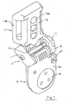
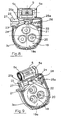
Figure 1 shows a perspective view of the adjustable holster securement device in accordance with the invention; -
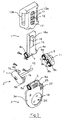
Figure 2 shows a partially exploded view of the holster securement device in accordance with the invention; - -
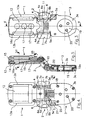
Figure 3 shows a front elevation of the device ofFigure 1 ; -
Figure 4 shows a rear view of the device ofFigure 1 ; -
Figure 5 shows a sectional view of the device ofFigure 3 taken along lines V-V ofFigure 3 ; -
Figures 6 and 7 show sectional views taken along, respectively, lines VI-VI and VII-VII ofFigure 5 ; -
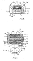
Figure 8 is an open plan view of the base to which the holster is attached; -
Figure 9 shows a perspective view of the base ofFigure 8 with the device for locking the rotation in the release position. - Referring to the aforesaid figures, the adjustable holster securement device in accordance with the invention is substantially made of three components:
- a
loop attachment 1 by means of which the holster securement device can be secured to the user's belt, - a
connection plate 3 to which the holster can be attached, - an articulated
joint 2 that connects theloop attachment 1 to theconnection plate 3 in an articulated manner. - From the sides of the
loop attachment 1 and theconnection plate 3, connected to each other by means of the articulatedjoint 2, twosleeves sleeves toothed gear - The seatings provided in the
sleeves joint 2, which also comprises two substantially U-shaped members, each of which is made up of anend element end elements sleeves toothed gears 6a, b and 7a, b are arranged at the base ofpins 8a, b and 9a, b in a coaxial relation with them.Gears 6a, b and 7a, b are designed to engage with corresponding frontallytoothed gears sleeve seatings stem 10 extends from one of the twoend elements locking nut 11 pivotally connected to theother end element joint 2.Stem 10 is parallel to the axes of thesleeve seatings - By rotating
locking nut 11, it is possible to screw it onto thestem 10, thus making it function as a tie rod that will gradually bring the substantially U-shaped members closer to each other and thus also bring the frontallytoothed gears sleeve seatings toothed gears 6a,b and 7a,b, until they eventually engage with each other and completely lock the articulated joint. It is thus possible to choose the preferred angular orientation for theconnection plate 3, and therefore also of the plane in which the holster lies, around the axis of the seatings of thesleeve 5, as well as the preferred angular orientation of thesleeve seatings 5 with respect to thesleeve seating 4, thereby displacing the planes ofloop attachment 1 andconnection plate 3 with respect to each other. Once the preferred angular orientations have been chosen, the articulatedjoint 2 can be locked by simply rotating thelocking nut 11 as described above. - The
loop attachment 1 comprises a box-shaped body 12 withbelt passages shaped body 12 defines aseat 14 for abracket 15 extending radially from thesleeve 4 and slidingly housed withinseat 14. Aflexible tongue 16 is cut from the bracket and is so shaped as to be slightly inclined with respect to the plane of thebracket 15. On one face of the box-like body 12 there are provided some axially aligned openings, (three openings and of circular shape in the present embodiment of the invention), while the free end of thetongue 16 has anenlargement 16a of such shape as to snap into a reversible engagement with one of theopenings 17, though partially projecting from it. When it is desired to adjust the length of the holster securement device, i.e. the distance of the holster from the belt engaged with theloop attachment 1, all that has to be done is to cause the bracket to slide with respect to the box-like body 12 and press with the fingers on thehead 16a of thetongue 16 to disengage it from the opening in which it is engaged and make it slide until it engages with another of theopenings 17. - The
connection plate 3 to which the holster is attached is actually formed by twoshells screws 18 to clasp between them the externally projectingedge 19a of a disc-shaped body 19 provided with means for the holster connection (in this specific case throughholes 20 for a screw connection). - As shown in
Figure 8 , along theedge 19a there is formed acavity 21 engaging with asmall cylinder 22 perpendicular to theshells body 19. For this purpose aseating 23 is formed on the inner face of theshell 3a, said seating being delimited by aU-shaped wall 24 within which one end of thesmall cylinder 22 is arranged. In stationary conditions thesmall cylinder 22 is prevented from sliding in theseating 23 by anarm 25 that rests elastically against it. Thearm 25 extends slidingly between the twoshells sleeve 5 between the sleeve and the disc-shapedbody 19. Anedge portion 25a ofarm 25 is shaped and made concave enough to bear against thesmall cylinder 22 and thus prevent it from sliding. Aspring 26 is arranged between the free end of thearm 25 and the edge of theshell 3a to keep theconcave portion 25a elastically forced against thesmall cylinder 22. A further and more concave portion 25b is formed adjacent to theconcave portion 25a along with the edge ofarm 25 in such a way as not to abut against thecylinder 22, which is therefore free to slide. When thesmall cylinder 22 is to be released, it is sufficient to press with a finger on thepushbutton end 27 of thearm 25 projecting sideways from theconnection plate 3 to overcome the elastic reaction of thespring 26 and make thearm 25 slide to bring the concave portion 25b in correspondence with the small cylinder 22 (Figure 9 ), which, being no longer retained, can therefore slide in a radial direction with respect to the disc-shapedbody 19. The radial displacement of thesmall cylinder 22 permits the rotation of the disc-shapedbody 19, so that the holster, which is attached to it, can be arranged in any desired inclined position. - In this case the stability of the holster in the chosen inclined position is assured by the resistance to relative sliding between the disc-shaped
body 19 and thesmall cylinder 22, which is forced by thearm 25 against theedge 19a. It is clear that a moderate force exerted on the holster can modify this position and also bring the holster back into its locked position. This possibility is often appropriate, especially when, according to the need, it is desired to make a fine adjustment of the variable configuration of the holster with a single hand. Otherwise, should it be desired to have several stable locking positions with different inclinations, it would be sufficient to provideadditional notches 21 at appropriate angular spacings along theedge 19a. - From the foregoing it is clear that the adjustable holster securement device according to the present invention allows all the previously recalled drawbacks associated with holster securement devices of the conventional type to be avoided. In particular, it should be noted that the fact that the system for regulating the height of the holster securement device is incorporated in the loop attachment not only allows for a significant reduction of the encumbrance of the
connection plate 3, but also offers the possibility of minimizing the number of components of the holster securement device that remain attached to the belt in all the conditions in which it is not necessary for the user to carry the weapon with him. In fact, thebracket 15 can be completely withdrawn from the box-shapedbody 12, so that the latter only remains attached to the belt in all these cases. - Variations, modifications and alterations to the present invention may be appreciated based on a review of the disclosure. These changes and additions are intended to be within the scope of the invention as defined by the following claims.
Claims (8)
- Adjustable holster securement device comprising a loop attachment (1) for securing the holster to a user's belt, a connection plate (3) to which a holster can be attached, an articulated joint (2) for connecting the loop attachment (1) to the connection plate (3) in an articulated way, characterized in that the articulated joint (2) is formed by two substantially U-shaped members (6,7; 8a,b;9a,b) pivotably engaged in respective seatings (4,5) at opposite sides thereof, the two pairs of seatings being coaxial and parallel and integral with, respectively, said loop attachment (1) and said connection plate (3), and comprises also tie-rod means (10,11) acting parallel to said seatings (4,5) to connect the substantially U-shaped members to each other and means (6a, b; 7a,b) for locking the articulated joint arranged between said substantially U-shaped members and said seatings and operable by said tie-rod means to control the locking and the release of said articulated joint.
- The device according to claim 1, wherein each of said substantially U-shaped members comprises an end element (6,7) and two parallel, spaced apart pins (8a,b; 9a,b) extending at right angles therefrom, said two pairs of coaxial seating (4,5) extending along the adjacent sides of said loop attachment (1) and said connection plate (3), said seatings being formed in sleeves with frontally toothed ends (4a, 5a), at the base of each pin a correspondingly toothed part (6a,b; 7a,b) being provided for engaging with a respective toothed end of said sleeves when, due to the action of said tie-rod means (10,11), said substantially U-shaped members are brought closer to each other, thereby locking the rotation of said pins within their respective seatings.
- The device according to claim 1 or claim 2, wherein said tie-rod means (10,11) comprise a pin (10) that extends from one of said substantially U-shaped members and engages by means of a screw thread with a seating provided in an operating locking nut (11) pivotably mounted on the other substantially U-shaped member.
- The device according to anyone of the preceding claims, wherein a bracket (15) slidingly engaged with a seating (14) of said loop attachment extends from the sleeve (4) extending along a side of said loop attachment (1), snap-type connection means (16,17) being provided on said bracket to permit its being reversibly locked in different positions with respect to said seating.
- The device according to claim 4, wherein a flexible tongue (16) is formed on said bracket (15), said tongue projecting at an angle therefrom and having an enlarged end (16a) selectively and reversibly engageable with corresponding longitudinally aligned openings (17) formed on said seating (14).
- The device according to anyone of the preceding claims, wherein said loop attachment (1) has two passages (13b) along two opposite sides.
- The device according to anyone of the preceding claims, wherein said connection plate (2) comprises a disc member (19) for supporting the holster mounted pivotably on said plate (2) and provided with at least one engagement cavity (21) along its edge (19a), and an elastically slidable arm (25) parallel to the sleeve (4) extending along one side of said plate, a body (22) constrained to slide in a direction at right angles to said arm being also provided, the arm having two concave portions (25a, 25b) of different depth on one of its sides, said concave portions defining two operating positions, namely a locking position of the rotation of said disc member (19), in which the less deep concave portion (25a9 of said arm (25) abuts against said body, to maintain it in said seating (21), and a rotation release position, in which the deeper concave portion (25b) is brought into correspondence with said body (22), thus allowing the body to slide in the radial direction with respect to said disc member (19) to disengage said body from said seating (21).
- The device according to claim 7, wherein said connection plate (3) is made up of two shells (3a, 3b), within which both said rotatable disc (19) and said sliding arm (25) are mounted, the latter being arranged between the edge of said disc member and the sleeve (4) extending along one side of said plate (3) and projects sideways beyond it with a pressure operated end (27).
Applications Claiming Priority (2)
| Application Number | Priority Date | Filing Date | Title |
|---|---|---|---|
| IT000145A ITFI20030145A1 (en) | 2003-05-23 | 2003-05-23 | ADJUSTABLE ADJUSTABLE HOLSTER HOLDER. |
| ITFI20030145 | 2003-05-23 |
Publications (3)
| Publication Number | Publication Date |
|---|---|
| EP1479998A2 EP1479998A2 (en) | 2004-11-24 |
| EP1479998A3 EP1479998A3 (en) | 2007-08-15 |
| EP1479998B1 true EP1479998B1 (en) | 2011-02-16 |
Family
ID=33042690
Family Applications (1)
| Application Number | Title | Priority Date | Filing Date |
|---|---|---|---|
| EP04425353A Active EP1479998B1 (en) | 2003-05-23 | 2004-05-18 | Improved adjustable holster securement device |
Country Status (6)
| Country | Link |
|---|---|
| US (1) | US7690541B2 (en) |
| EP (1) | EP1479998B1 (en) |
| AT (1) | ATE498815T1 (en) |
| DE (1) | DE602004031394D1 (en) |
| ES (1) | ES2359976T3 (en) |
| IT (1) | ITFI20030145A1 (en) |
Families Citing this family (24)
| Publication number | Priority date | Publication date | Assignee | Title |
|---|---|---|---|---|
| CA2704486A1 (en) | 2007-10-30 | 2009-09-03 | Das Land Nordrhein-Westfalen, Dieses Vetreten Durch Das Innenministerium Nrw, Dieses Vertreten Durch Das Landesamt Fuer Zentrale Polizeiliche Die | Weapon holster with adjustable draw angle, in particular for hand firearms and latching joint unit, in particular for weapon holsters |
| US8783532B2 (en) * | 2010-01-13 | 2014-07-22 | Alliant Techsystems Inc. | Multi-disk accessory attachment platform |
| ITFI20110080A1 (en) | 2011-04-20 | 2012-10-21 | Radar Leather Division S R L | HOLSTER SUPPORT |
| JP5779017B2 (en) * | 2011-07-08 | 2015-09-16 | 三郎 林 | Case for connecting drill |
| US9271561B2 (en) * | 2013-02-08 | 2016-03-01 | David Chang | Apparatus for improving the interchangeability of portable electronic devices amongst various supports and related methods |
| US9408456B2 (en) * | 2013-06-27 | 2016-08-09 | John Kenison Hart | Universal mobile device holder |
| US9797679B2 (en) * | 2014-02-18 | 2017-10-24 | Wild Bucks Outdoors, LLC | Hands-free support device, a subassembly of a hands-free support device and methods for operating the same |
| US9835410B2 (en) | 2014-07-23 | 2017-12-05 | Blue Line Tactical, Llc | Rotatable holster |
| US20180010885A1 (en) * | 2016-07-07 | 2018-01-11 | Tedder Industries, LLC | Adjustable Clip |
| CN106500544A (en) * | 2017-01-05 | 2017-03-15 | 张勇 | A kind of holster with convenient plug and the protection mechanism of guarding against theft |
| US10575625B2 (en) * | 2017-07-24 | 2020-03-03 | Kevin Senn | Systems and methods associated with a container holder |
| US10883795B2 (en) | 2018-01-18 | 2021-01-05 | Safariland, Llc | Holster mount with adjustable drop and cant |
| US10782094B2 (en) | 2018-01-18 | 2020-09-22 | Safariland, Llc | Holster mount with adjustable drop and cant |
| US10996024B2 (en) | 2018-03-23 | 2021-05-04 | Vista Outdoor Operations Llc | Thumb-actuated locking holster |
| US10619974B2 (en) | 2018-03-23 | 2020-04-14 | Vista Outdoor Operations Llc | Thumb-actuated locking holster |
| EP3553456B1 (en) * | 2018-04-11 | 2021-05-19 | Safariland, LLC | Holster mount |
| US10883796B2 (en) * | 2018-07-13 | 2021-01-05 | Edge-Works Manufacturing Company | Adjustable position magazine carrier |
| ES2762298B2 (en) | 2018-11-21 | 2021-11-16 | Ruiz Jorge Garcia | QUICK RELEASE GUNS, BRACKET, CASE AND ANCHOR SYSTEM |
| CN116551640A (en) | 2019-02-12 | 2023-08-08 | 米沃奇电动工具公司 | Tool attachment system |
| US11666135B2 (en) * | 2019-07-01 | 2023-06-06 | Randy Dellwo | Smartphone holster |
| US11143487B1 (en) | 2020-03-24 | 2021-10-12 | John Alexander Reich | Multiple-position firearm holster adapter and system |
| US11781831B2 (en) * | 2020-06-12 | 2023-10-10 | Vista Outdoor Operations Llc | Thumb-actuated locking holster system |
| US11397069B2 (en) | 2020-12-04 | 2022-07-26 | Vista Outdoor Operations Llc | Locking holster system |
| WO2024044808A1 (en) * | 2022-08-29 | 2024-03-07 | Beaumont Jones James | A compact rod holder |
Family Cites Families (6)
| Publication number | Priority date | Publication date | Assignee | Title |
|---|---|---|---|---|
| US3589574A (en) * | 1969-06-30 | 1971-06-29 | Fred R Marburger | Adjustable belt loop assembly for pistol holsters and the like |
| US5421497A (en) * | 1993-08-26 | 1995-06-06 | Gilmore; W. Riley | Variable position handgun holster |
| DE9313311U1 (en) * | 1993-09-04 | 1993-11-18 | Nowar Security Equipment Gmbh | Pendulum bridge holster |
| US6161741A (en) * | 1999-06-14 | 2000-12-19 | Michaels Of Oregon Co. | Holster securement system |
| ITFI20010090A1 (en) * | 2001-05-16 | 2002-11-16 | Gargani Elsa | ADJUSTABLE INCLINATION HOLT HOLDER PASS-THROUGH QUICK RELEASE SYSTEM |
| ITPI20010082A1 (en) * | 2001-12-05 | 2002-03-05 | Alfonso Leto | ADJUSTABLE DEVICE FOR THE APPLICATION OF THE PISTOL HOLSTER TO THE OPERATOR BELT. |
-
2003
- 2003-05-23 IT IT000145A patent/ITFI20030145A1/en unknown
-
2004
- 2004-05-18 DE DE602004031394T patent/DE602004031394D1/en active Active
- 2004-05-18 ES ES04425353T patent/ES2359976T3/en active Active
- 2004-05-18 AT AT04425353T patent/ATE498815T1/en not_active IP Right Cessation
- 2004-05-18 EP EP04425353A patent/EP1479998B1/en active Active
- 2004-05-23 US US10/852,332 patent/US7690541B2/en active Active
Also Published As
| Publication number | Publication date |
|---|---|
| US20040251284A1 (en) | 2004-12-16 |
| EP1479998A3 (en) | 2007-08-15 |
| ATE498815T1 (en) | 2011-03-15 |
| DE602004031394D1 (en) | 2011-03-31 |
| ES2359976T3 (en) | 2011-05-30 |
| ITFI20030145A1 (en) | 2004-11-24 |
| US7690541B2 (en) | 2010-04-06 |
| EP1479998A2 (en) | 2004-11-24 |
Similar Documents
| Publication | Publication Date | Title |
|---|---|---|
| EP1479998B1 (en) | Improved adjustable holster securement device | |
| US6431025B1 (en) | Ratchet mechanism for a surgical retractor assembly | |
| EP0942665B1 (en) | Adjustable helmet having an improved locking mechanism | |
| US5988577A (en) | Adjustable carrier assembly for a wireless communication device | |
| US5292303A (en) | Hinged orthopedic brace having an adjustable pivot range | |
| US5689827A (en) | Fastener assemblies for combination visor and eyeshield | |
| US4512051A (en) | Handtool | |
| US7083583B2 (en) | Orthesis comprising an adjustable range of movement | |
| CA2561540C (en) | Adjustment mechanism for a helmet | |
| US6108824A (en) | Helmet adjustment mechanism with quick release | |
| US5672152A (en) | Hinge for an orthopedic brace having an adjustable range of rotation | |
| US20060155230A1 (en) | Releasably locking hinge for an orthopedic brace having adjustable rotation limits | |
| US20040055200A1 (en) | Modular gunstock | |
| US20020148865A1 (en) | Holster securement system | |
| US7975318B2 (en) | Head strap | |
| US9889036B2 (en) | Joint orthosis | |
| US6010045A (en) | Adjustable carrier | |
| US6745480B1 (en) | Saw having an angle adjustable blade | |
| US5050414A (en) | Structure of key-ring assembly | |
| CA2572905A1 (en) | Lock | |
| US10274296B2 (en) | Modular carrier | |
| US4040416A (en) | Orthopedic splint | |
| US20190084817A1 (en) | Pivoting prybar head | |
| US6957866B1 (en) | Adjustable armrest assembly for chair | |
| US20070028428A1 (en) | Strap attachment device |
Legal Events
| Date | Code | Title | Description |
|---|---|---|---|
| PUAI | Public reference made under article 153(3) epc to a published international application that has entered the european phase |
Free format text: ORIGINAL CODE: 0009012 |
|
| AK | Designated contracting states |
Kind code of ref document: A2 Designated state(s): AT BE BG CH CY CZ DE DK EE ES FI FR GB GR HU IE IT LI LU MC NL PL PT RO SE SI SK TR |
|
| AX | Request for extension of the european patent |
Extension state: AL HR LT LV MK |
|
| PUAL | Search report despatched |
Free format text: ORIGINAL CODE: 0009013 |
|
| AK | Designated contracting states |
Kind code of ref document: A3 Designated state(s): AT BE BG CH CY CZ DE DK EE ES FI FR GB GR HU IE IT LI LU MC NL PL PT RO SE SI SK TR |
|
| AX | Request for extension of the european patent |
Extension state: AL HR LT LV MK |
|
| AKX | Designation fees paid | ||
| REG | Reference to a national code |
Ref country code: DE Ref legal event code: 8566 |
|
| RBV | Designated contracting states (corrected) |
Designated state(s): AT BE BG CH CY CZ DE DK EE ES FI FR GB GR HU IE IT LI LU MC NL PL PT RO SE SI SK TR |
|
| 17P | Request for examination filed |
Effective date: 20080528 |
|
| 17Q | First examination report despatched |
Effective date: 20080930 |
|
| GRAP | Despatch of communication of intention to grant a patent |
Free format text: ORIGINAL CODE: EPIDOSNIGR1 |
|
| RIC1 | Information provided on ipc code assigned before grant |
Ipc: F41C 33/04 20060101AFI20100628BHEP |
|
| GRAS | Grant fee paid |
Free format text: ORIGINAL CODE: EPIDOSNIGR3 |
|
| GRAA | (expected) grant |
Free format text: ORIGINAL CODE: 0009210 |
|
| AK | Designated contracting states |
Kind code of ref document: B1 Designated state(s): AT BE BG CH CY CZ DE DK EE ES FI FR GB GR HU IE IT LI LU MC NL PL PT RO SE SI SK TR |
|
| REG | Reference to a national code |
Ref country code: GB Ref legal event code: FG4D |
|
| REG | Reference to a national code |
Ref country code: CH Ref legal event code: EP |
|
| REG | Reference to a national code |
Ref country code: IE Ref legal event code: FG4D |
|
| REF | Corresponds to: |
Ref document number: 602004031394 Country of ref document: DE Date of ref document: 20110331 Kind code of ref document: P |
|
| REG | Reference to a national code |
Ref country code: DE Ref legal event code: R096 Ref document number: 602004031394 Country of ref document: DE Effective date: 20110331 |
|
| REG | Reference to a national code |
Ref country code: ES Ref legal event code: FG2A Ref document number: 2359976 Country of ref document: ES Kind code of ref document: T3 Effective date: 20110530 |
|
| REG | Reference to a national code |
Ref country code: NL Ref legal event code: VDEP Effective date: 20110216 |
|
| PG25 | Lapsed in a contracting state [announced via postgrant information from national office to epo] |
Ref country code: PT Free format text: LAPSE BECAUSE OF FAILURE TO SUBMIT A TRANSLATION OF THE DESCRIPTION OR TO PAY THE FEE WITHIN THE PRESCRIBED TIME-LIMIT Effective date: 20110616 Ref country code: GR Free format text: LAPSE BECAUSE OF FAILURE TO SUBMIT A TRANSLATION OF THE DESCRIPTION OR TO PAY THE FEE WITHIN THE PRESCRIBED TIME-LIMIT Effective date: 20110517 Ref country code: SE Free format text: LAPSE BECAUSE OF FAILURE TO SUBMIT A TRANSLATION OF THE DESCRIPTION OR TO PAY THE FEE WITHIN THE PRESCRIBED TIME-LIMIT Effective date: 20110216 |
|
| PG25 | Lapsed in a contracting state [announced via postgrant information from national office to epo] |
Ref country code: BE Free format text: LAPSE BECAUSE OF FAILURE TO SUBMIT A TRANSLATION OF THE DESCRIPTION OR TO PAY THE FEE WITHIN THE PRESCRIBED TIME-LIMIT Effective date: 20110216 Ref country code: BG Free format text: LAPSE BECAUSE OF FAILURE TO SUBMIT A TRANSLATION OF THE DESCRIPTION OR TO PAY THE FEE WITHIN THE PRESCRIBED TIME-LIMIT Effective date: 20110516 Ref country code: NL Free format text: LAPSE BECAUSE OF FAILURE TO SUBMIT A TRANSLATION OF THE DESCRIPTION OR TO PAY THE FEE WITHIN THE PRESCRIBED TIME-LIMIT Effective date: 20110216 Ref country code: FI Free format text: LAPSE BECAUSE OF FAILURE TO SUBMIT A TRANSLATION OF THE DESCRIPTION OR TO PAY THE FEE WITHIN THE PRESCRIBED TIME-LIMIT Effective date: 20110216 Ref country code: CY Free format text: LAPSE BECAUSE OF FAILURE TO SUBMIT A TRANSLATION OF THE DESCRIPTION OR TO PAY THE FEE WITHIN THE PRESCRIBED TIME-LIMIT Effective date: 20110216 Ref country code: SI Free format text: LAPSE BECAUSE OF FAILURE TO SUBMIT A TRANSLATION OF THE DESCRIPTION OR TO PAY THE FEE WITHIN THE PRESCRIBED TIME-LIMIT Effective date: 20110216 Ref country code: AT Free format text: LAPSE BECAUSE OF FAILURE TO SUBMIT A TRANSLATION OF THE DESCRIPTION OR TO PAY THE FEE WITHIN THE PRESCRIBED TIME-LIMIT Effective date: 20110216 Ref country code: PL Free format text: LAPSE BECAUSE OF FAILURE TO SUBMIT A TRANSLATION OF THE DESCRIPTION OR TO PAY THE FEE WITHIN THE PRESCRIBED TIME-LIMIT Effective date: 20110216 |
|
| PG25 | Lapsed in a contracting state [announced via postgrant information from national office to epo] |
Ref country code: EE Free format text: LAPSE BECAUSE OF FAILURE TO SUBMIT A TRANSLATION OF THE DESCRIPTION OR TO PAY THE FEE WITHIN THE PRESCRIBED TIME-LIMIT Effective date: 20110216 Ref country code: DK Free format text: LAPSE BECAUSE OF FAILURE TO SUBMIT A TRANSLATION OF THE DESCRIPTION OR TO PAY THE FEE WITHIN THE PRESCRIBED TIME-LIMIT Effective date: 20110216 |
|
| PG25 | Lapsed in a contracting state [announced via postgrant information from national office to epo] |
Ref country code: SK Free format text: LAPSE BECAUSE OF FAILURE TO SUBMIT A TRANSLATION OF THE DESCRIPTION OR TO PAY THE FEE WITHIN THE PRESCRIBED TIME-LIMIT Effective date: 20110216 Ref country code: CZ Free format text: LAPSE BECAUSE OF FAILURE TO SUBMIT A TRANSLATION OF THE DESCRIPTION OR TO PAY THE FEE WITHIN THE PRESCRIBED TIME-LIMIT Effective date: 20110216 Ref country code: RO Free format text: LAPSE BECAUSE OF FAILURE TO SUBMIT A TRANSLATION OF THE DESCRIPTION OR TO PAY THE FEE WITHIN THE PRESCRIBED TIME-LIMIT Effective date: 20110216 |
|
| PLBE | No opposition filed within time limit |
Free format text: ORIGINAL CODE: 0009261 |
|
| STAA | Information on the status of an ep patent application or granted ep patent |
Free format text: STATUS: NO OPPOSITION FILED WITHIN TIME LIMIT |
|
| PG25 | Lapsed in a contracting state [announced via postgrant information from national office to epo] |
Ref country code: MC Free format text: LAPSE BECAUSE OF NON-PAYMENT OF DUE FEES Effective date: 20110531 |
|
| REG | Reference to a national code |
Ref country code: CH Ref legal event code: PL |
|
| 26N | No opposition filed |
Effective date: 20111117 |
|
| PG25 | Lapsed in a contracting state [announced via postgrant information from national office to epo] |
Ref country code: LI Free format text: LAPSE BECAUSE OF NON-PAYMENT OF DUE FEES Effective date: 20110531 Ref country code: CH Free format text: LAPSE BECAUSE OF NON-PAYMENT OF DUE FEES Effective date: 20110531 |
|
| REG | Reference to a national code |
Ref country code: IE Ref legal event code: MM4A |
|
| REG | Reference to a national code |
Ref country code: DE Ref legal event code: R097 Ref document number: 602004031394 Country of ref document: DE Effective date: 20111117 |
|
| PG25 | Lapsed in a contracting state [announced via postgrant information from national office to epo] |
Ref country code: IE Free format text: LAPSE BECAUSE OF NON-PAYMENT OF DUE FEES Effective date: 20110518 |
|
| PG25 | Lapsed in a contracting state [announced via postgrant information from national office to epo] |
Ref country code: IT Free format text: LAPSE BECAUSE OF FAILURE TO SUBMIT A TRANSLATION OF THE DESCRIPTION OR TO PAY THE FEE WITHIN THE PRESCRIBED TIME-LIMIT Effective date: 20110216 |
|
| PG25 | Lapsed in a contracting state [announced via postgrant information from national office to epo] |
Ref country code: LU Free format text: LAPSE BECAUSE OF NON-PAYMENT OF DUE FEES Effective date: 20110518 |
|
| PG25 | Lapsed in a contracting state [announced via postgrant information from national office to epo] |
Ref country code: TR Free format text: LAPSE BECAUSE OF FAILURE TO SUBMIT A TRANSLATION OF THE DESCRIPTION OR TO PAY THE FEE WITHIN THE PRESCRIBED TIME-LIMIT Effective date: 20110216 |
|
| PG25 | Lapsed in a contracting state [announced via postgrant information from national office to epo] |
Ref country code: HU Free format text: LAPSE BECAUSE OF FAILURE TO SUBMIT A TRANSLATION OF THE DESCRIPTION OR TO PAY THE FEE WITHIN THE PRESCRIBED TIME-LIMIT Effective date: 20110216 |
|
| REG | Reference to a national code |
Ref country code: FR Ref legal event code: PLFP Year of fee payment: 12 |
|
| PGFP | Annual fee paid to national office [announced via postgrant information from national office to epo] |
Ref country code: ES Payment date: 20150527 Year of fee payment: 12 Ref country code: GB Payment date: 20150521 Year of fee payment: 12 |
|
| PGFP | Annual fee paid to national office [announced via postgrant information from national office to epo] |
Ref country code: FR Payment date: 20150521 Year of fee payment: 12 |
|
| GBPC | Gb: european patent ceased through non-payment of renewal fee |
Effective date: 20160518 |
|
| REG | Reference to a national code |
Ref country code: FR Ref legal event code: ST Effective date: 20170131 |
|
| PG25 | Lapsed in a contracting state [announced via postgrant information from national office to epo] |
Ref country code: FR Free format text: LAPSE BECAUSE OF NON-PAYMENT OF DUE FEES Effective date: 20160531 |
|
| PG25 | Lapsed in a contracting state [announced via postgrant information from national office to epo] |
Ref country code: GB Free format text: LAPSE BECAUSE OF NON-PAYMENT OF DUE FEES Effective date: 20160518 |
|
| PG25 | Lapsed in a contracting state [announced via postgrant information from national office to epo] |
Ref country code: ES Free format text: LAPSE BECAUSE OF NON-PAYMENT OF DUE FEES Effective date: 20160519 |
|
| REG | Reference to a national code |
Ref country code: ES Ref legal event code: FD2A Effective date: 20180626 |
|
| PGFP | Annual fee paid to national office [announced via postgrant information from national office to epo] |
Ref country code: DE Payment date: 20220620 Year of fee payment: 20 |