EP1479928B1 - End connection device for an operating cable, with system for ensuring correct assembly - Google Patents
End connection device for an operating cable, with system for ensuring correct assembly Download PDFInfo
- Publication number
- EP1479928B1 EP1479928B1 EP04011348A EP04011348A EP1479928B1 EP 1479928 B1 EP1479928 B1 EP 1479928B1 EP 04011348 A EP04011348 A EP 04011348A EP 04011348 A EP04011348 A EP 04011348A EP 1479928 B1 EP1479928 B1 EP 1479928B1
- Authority
- EP
- European Patent Office
- Prior art keywords
- seat
- bush
- ball head
- operating cable
- connection device
- Prior art date
- Legal status (The legal status is an assumption and is not a legal conclusion. Google has not performed a legal analysis and makes no representation as to the accuracy of the status listed.)
- Expired - Lifetime
Links
- 230000037431 insertion Effects 0.000 claims description 5
- 238000003780 insertion Methods 0.000 claims description 5
- 239000002184 metal Substances 0.000 description 1
- 238000010137 moulding (plastic) Methods 0.000 description 1
Images

Classifications
-
- F—MECHANICAL ENGINEERING; LIGHTING; HEATING; WEAPONS; BLASTING
- F16—ENGINEERING ELEMENTS AND UNITS; GENERAL MEASURES FOR PRODUCING AND MAINTAINING EFFECTIVE FUNCTIONING OF MACHINES OR INSTALLATIONS; THERMAL INSULATION IN GENERAL
- F16C—SHAFTS; FLEXIBLE SHAFTS; ELEMENTS OR CRANKSHAFT MECHANISMS; ROTARY BODIES OTHER THAN GEARING ELEMENTS; BEARINGS
- F16C11/00—Pivots; Pivotal connections
- F16C11/04—Pivotal connections
- F16C11/06—Ball-joints; Other joints having more than one degree of angular freedom, i.e. universal joints
- F16C11/0619—Ball-joints; Other joints having more than one degree of angular freedom, i.e. universal joints the female part comprising a blind socket receiving the male part
- F16C11/0623—Construction or details of the socket member
- F16C11/0628—Construction or details of the socket member with linings
- F16C11/0633—Construction or details of the socket member with linings the linings being made of plastics
- F16C11/0638—Construction or details of the socket member with linings the linings being made of plastics characterised by geometrical details
-
- F—MECHANICAL ENGINEERING; LIGHTING; HEATING; WEAPONS; BLASTING
- F16—ENGINEERING ELEMENTS AND UNITS; GENERAL MEASURES FOR PRODUCING AND MAINTAINING EFFECTIVE FUNCTIONING OF MACHINES OR INSTALLATIONS; THERMAL INSULATION IN GENERAL
- F16C—SHAFTS; FLEXIBLE SHAFTS; ELEMENTS OR CRANKSHAFT MECHANISMS; ROTARY BODIES OTHER THAN GEARING ELEMENTS; BEARINGS
- F16C1/00—Flexible shafts; Mechanical means for transmitting movement in a flexible sheathing
- F16C1/10—Means for transmitting linear movement in a flexible sheathing, e.g. "Bowden-mechanisms"
- F16C1/12—Arrangements for transmitting movement to or from the flexible member
-
- F—MECHANICAL ENGINEERING; LIGHTING; HEATING; WEAPONS; BLASTING
- F16—ENGINEERING ELEMENTS AND UNITS; GENERAL MEASURES FOR PRODUCING AND MAINTAINING EFFECTIVE FUNCTIONING OF MACHINES OR INSTALLATIONS; THERMAL INSULATION IN GENERAL
- F16C—SHAFTS; FLEXIBLE SHAFTS; ELEMENTS OR CRANKSHAFT MECHANISMS; ROTARY BODIES OTHER THAN GEARING ELEMENTS; BEARINGS
- F16C2361/00—Apparatus or articles in engineering in general
- F16C2361/65—Gear shifting, change speed gear, gear box
-
- F—MECHANICAL ENGINEERING; LIGHTING; HEATING; WEAPONS; BLASTING
- F16—ENGINEERING ELEMENTS AND UNITS; GENERAL MEASURES FOR PRODUCING AND MAINTAINING EFFECTIVE FUNCTIONING OF MACHINES OR INSTALLATIONS; THERMAL INSULATION IN GENERAL
- F16H—GEARING
- F16H61/00—Control functions within control units of change-speed- or reversing-gearings for conveying rotary motion ; Control of exclusively fluid gearing, friction gearing, gearings with endless flexible members or other particular types of gearing
- F16H61/26—Generation or transmission of movements for final actuating mechanisms
- F16H61/36—Generation or transmission of movements for final actuating mechanisms with at least one movement being transmitted by a cable
-
- Y—GENERAL TAGGING OF NEW TECHNOLOGICAL DEVELOPMENTS; GENERAL TAGGING OF CROSS-SECTIONAL TECHNOLOGIES SPANNING OVER SEVERAL SECTIONS OF THE IPC; TECHNICAL SUBJECTS COVERED BY FORMER USPC CROSS-REFERENCE ART COLLECTIONS [XRACs] AND DIGESTS
- Y10—TECHNICAL SUBJECTS COVERED BY FORMER USPC
- Y10T—TECHNICAL SUBJECTS COVERED BY FORMER US CLASSIFICATION
- Y10T403/00—Joints and connections
- Y10T403/20—Joints and connections with indicator or inspection means
-
- Y—GENERAL TAGGING OF NEW TECHNOLOGICAL DEVELOPMENTS; GENERAL TAGGING OF CROSS-SECTIONAL TECHNOLOGIES SPANNING OVER SEVERAL SECTIONS OF THE IPC; TECHNICAL SUBJECTS COVERED BY FORMER USPC CROSS-REFERENCE ART COLLECTIONS [XRACs] AND DIGESTS
- Y10—TECHNICAL SUBJECTS COVERED BY FORMER USPC
- Y10T—TECHNICAL SUBJECTS COVERED BY FORMER US CLASSIFICATION
- Y10T403/00—Joints and connections
- Y10T403/32—Articulated members
- Y10T403/32606—Pivoted
- Y10T403/32631—Universal ball and socket
- Y10T403/32721—Elastomeric seat
Definitions
- the present invention relates to an end connection device, or terminal device, for an operating cable of the so-called push-pull type according to the preamble of claim 1.
- An end connection device having the characteristics set forth in the preamble of Claim 1 is known from US-A-4478531.
- the terminal device must allow a jointed connection between the end of the cable and the control member.
- the terminal device which is usually assembled on the control member, for example at one end of the gear shift lever, has a spherical seat into which the ball head of a pin attached to one end of the operating cable is to be snap-engaged. A releasable connection between the cable and the control member is thus achieved.
- German Patent Application DE 198 13 721 A1 discloses a terminal device designed to reduce the force required to insert the ball head of the pin associated to the control lever into the spherical seat formed in the hollow terminal, without thereby reducing the disassembly force and so risking causing the ball head to disengage from its seat during operation.
- this known device comprises:
- the spherical seat With the bush in the first position, the spherical seat can expand, because of the presence of slits, to snap-engage the ball head of the pin.
- the whole portion of bush forming the spherical seat is contained in the sleeve inside the terminal body, and is therefore now unable to expand to allow the ball head to disengage from its seat.
- the terminal can adopt a pre-assembled condition, in which the ball head is received in the associated seat in the bush, and the bush is held in the terminal body by its own catches engaging in the abovementioned first recesses.
- this represents a disadvantage, because if a terminal is left in the pre-assembled condition it can erroneously be assumed by the operator to be in the final assembled condition, with the inevitable consequence that the cable will come out of the control member as soon as the cable is operated in normal use.
- an end connection device according to the present invention is generally indicated 10.
- the device 10 comprises an outer body 11 intended to be connected in a manner known per se, for example by a connection rod (not shown), to one end of an operating cable (also not shown).
- the body 11, which is preferably formed by plastic moulding, has a central through opening 12 suitable for receiving at a (lower) end a bush 13 and closed at the other (upper) end by a cap or cover 14 (shown in Figures 2 and 3).
- the body 11 is advantageously over-moulded onto the connection rod, which is generally made of metal and is arranged perpendicular to the axis of the opening 12.
- the bush 13 has at its lower end a spherical seat 15 suitable for receiving and snap-engaging, in a manner known per se, a ball head 16 of a pin 17 attached to a control member (not shown), such as the control lever of a motor vehicle gearbox.
- the seat 15 is bounded at its lower end by a circumferential edge 18 of slightly smaller diameter than that of the ball head 16.
- the bush 13 forms a lead-in portion 19 which has a tapering inner surface 20.
- the lead-in portion 19 In order to insert the head 16 into the seat 15 the lead-in portion 19 must therefore be expanded elastically, particularly at the circumferential edge 18.
- a series of notches 21 are formed in the portion 19 which are oriented vertically, that is in the direction in which the head 16 is inserted into the bush 13, thereby dividing the portion 19 into elastically deformable segments.
- An upper portion of the bush 13 forms an annular protuberance 22 projecting radially from the outer surface of the bush for snap-engaging with a series of ramp-shaped projections 23 provided on the internal surface of the cavity 12 of the body 11.
- a series of notches 24 oriented vertically, that is in the direction in which the bush slides into the cavity 12, thereby dividing this portion into elastically deformable segments.
- the body 11 also forms at the top end of the cavity 12 a series of protrusions 25 projecting radially inwards and defining an upper limit position for the bush 13 in cooperation with the annular protuberance 22 of the bush.
- the projections 23 on the body 11 can be formed as a single annular projection running all the way around the circumference of the cavity 12. The same applies for the protrusions 25.
- the bush 13 is provided with an elastically deformable element 30, which in its undeformed condition extends into the spherical seat 15 in such a way as to oppose the insertion of the ball head 16.
- the element 30 consists of four curvilinear arms 31, substantially in the form of circular arcs, formed integrally with the bush 13, which extend radially from the top of the spherical seat 15 and are connected to each other at their lower ends.
- the elastic element 30 defines an upper abutment surface with which the ball head 16 comes into contact before or as soon as the latter has begun to elastically deform the lead-in portion 19 of the bush 13 by acting on the circumferential edge 18.
- the shape and dimensions of the elastic element 30 may of course be varied from those illustrated, provided the element is stiff enough to oppose the insertion of the ball head 16 into the seat 15 unless sufficient force is exerted on the head 16 to move the head and bush assembly into the final assembled position described above, in which the protuberance 22 on the bush snap-engages with the projections 23 of the body 11.
Landscapes
- General Engineering & Computer Science (AREA)
- Engineering & Computer Science (AREA)
- Mechanical Engineering (AREA)
- Oral & Maxillofacial Surgery (AREA)
- Geometry (AREA)
- Health & Medical Sciences (AREA)
- Physics & Mathematics (AREA)
- Pivots And Pivotal Connections (AREA)
- Gear-Shifting Mechanisms (AREA)
- Arrangement Or Mounting Of Control Devices For Change-Speed Gearing (AREA)
- Flexible Shafts (AREA)
- Mechanical Control Devices (AREA)
- Seats For Vehicles (AREA)
Description
- The present invention relates to an end connection device, or terminal device, for an operating cable of the so-called push-pull type according to the preamble of claim 1. An end connection device having the characteristics set forth in the preamble of Claim 1 is known from US-A-4478531.
- These devices are often used, especially in the automotive field, for connecting one end of an operating cable to a control member, such as the control lever of the gearbox of a motor vehicle.
- The terminal device must allow a jointed connection between the end of the cable and the control member. For this purpose the terminal device, which is usually assembled on the control member, for example at one end of the gear shift lever, has a spherical seat into which the ball head of a pin attached to one end of the operating cable is to be snap-engaged. A releasable connection between the cable and the control member is thus achieved.
- German Patent Application DE 198 13 721 A1, for example, discloses a terminal device designed to reduce the force required to insert the ball head of the pin associated to the control lever into the spherical seat formed in the hollow terminal, without thereby reducing the disassembly force and so risking causing the ball head to disengage from its seat during operation. To this end, this known device comprises:
- an outer body connected to the operating cable by a connection rod and having an opening arranged perpendicularly to the rod;
- a ball headed pin assembled on the end of the control lever;
- a sleeve inserted into the opening of the outer body and having at least two first recesses and two second recesses defining a first position and a second position, respectively;
- a bush slidably mounted in the sleeve and having a spherical seat for accommodating the ball head of the pin; the bush being provided with elastic catches for engaging in the recesses of the sleeve in order to lock the bush in the abovementioned two positions inside the cavity of the terminal body.
- With the bush in the first position, the spherical seat can expand, because of the presence of slits, to snap-engage the ball head of the pin. When the bush is moved into the second position, the whole portion of bush forming the spherical seat is contained in the sleeve inside the terminal body, and is therefore now unable to expand to allow the ball head to disengage from its seat.
- According to this known arrangement, therefore, the terminal can adopt a pre-assembled condition, in which the ball head is received in the associated seat in the bush, and the bush is held in the terminal body by its own catches engaging in the abovementioned first recesses. During assembly, however, this represents a disadvantage, because if a terminal is left in the pre-assembled condition it can erroneously be assumed by the operator to be in the final assembled condition, with the inevitable consequence that the cable will come out of the control member as soon as the cable is operated in normal use.
- It is an object of the present invention to provide an end connection device for an operating cable that will retain the advantages of the prior art discussed above but that cannot be mistakenly left in the pre-assembled condition.
- This and other objects are achieved according to the invention by virtue of an end connection device having the features defined in Claim 1.
- Further features and advantages of the device according to the invention will result clearly from the detailed description which follows, with reference to the accompanying drawings, in which:
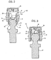
- Figure 1 is a perspective view, sectioned on an axial plane, showing part of an end connection device according to the invention, in the pre-assembled condition;
- Figures 2 and 3 are views in axial section of the device of Figure 1, in the pre-assembled condition and final assembled condition, respectively; and
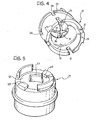
- Figures 4 and 5 are perspective views of a bush and an outer body, respectively, that form part of a device according to the invention.
- Referring to the figures, an end connection device according to the present invention is generally indicated 10. The
device 10 comprises anouter body 11 intended to be connected in a manner known per se, for example by a connection rod (not shown), to one end of an operating cable (also not shown). Thebody 11, which is preferably formed by plastic moulding, has a central through opening 12 suitable for receiving at a (lower) end abush 13 and closed at the other (upper) end by a cap or cover 14 (shown in Figures 2 and 3). Thebody 11 is advantageously over-moulded onto the connection rod, which is generally made of metal and is arranged perpendicular to the axis of theopening 12. - The
bush 13 has at its lower end aspherical seat 15 suitable for receiving and snap-engaging, in a manner known per se, aball head 16 of apin 17 attached to a control member (not shown), such as the control lever of a motor vehicle gearbox. Theseat 15 is bounded at its lower end by acircumferential edge 18 of slightly smaller diameter than that of theball head 16. Below thecircumferential edge 18, thebush 13 forms a lead-inportion 19 which has a taperinginner surface 20. In order to insert thehead 16 into theseat 15 the lead-inportion 19 must therefore be expanded elastically, particularly at thecircumferential edge 18. For this purpose a series ofnotches 21 are formed in theportion 19 which are oriented vertically, that is in the direction in which thehead 16 is inserted into thebush 13, thereby dividing theportion 19 into elastically deformable segments. - An upper portion of the
bush 13 forms anannular protuberance 22 projecting radially from the outer surface of the bush for snap-engaging with a series of ramp-shaped projections 23 provided on the internal surface of thecavity 12 of thebody 11. Once again, there are formed in the upper portion of thebush 13, which forms theprotrusion 22, a series ofnotches 24 oriented vertically, that is in the direction in which the bush slides into thecavity 12, thereby dividing this portion into elastically deformable segments. In this way, when thebush 13 is pushed up into thecavity 12, starting from the position shown in Figure 2, the deformable segments of the upper portion of the bush bend radially inwards due to theprotuberance 22 sliding over the ramp surface of theprojections 23 on thebody 11, until the protuberance moves past theprojections 23. In this position (Figure 3), corresponding to the assembled condition of the device, thebush 13 is locked axially downwards in thecavity 12, as well as theball head 16 is locked axially in theseat 15 of the bush. - The
body 11 also forms at the top end of the cavity 12 a series ofprotrusions 25 projecting radially inwards and defining an upper limit position for thebush 13 in cooperation with theannular protuberance 22 of the bush. - Clearly, the
projections 23 on thebody 11 can be formed as a single annular projection running all the way around the circumference of thecavity 12. The same applies for theprotrusions 25. - In order to prevent the connection device from being erroneously left in a pre-assembled condition in which the
ball head 16 is received in theseat 15, but thebush 13 is not fully inserted into thecavity 12 and therefore does not ensure that thehead 16 is locked in its seat, according to the invention thebush 13 is provided with an elasticallydeformable element 30, which in its undeformed condition extends into thespherical seat 15 in such a way as to oppose the insertion of theball head 16. In the illustrated embodiment, theelement 30 consists of fourcurvilinear arms 31, substantially in the form of circular arcs, formed integrally with thebush 13, which extend radially from the top of thespherical seat 15 and are connected to each other at their lower ends. In the undeformed condition (Figure 2) theelastic element 30 defines an upper abutment surface with which theball head 16 comes into contact before or as soon as the latter has begun to elastically deform the lead-inportion 19 of thebush 13 by acting on thecircumferential edge 18. - The shape and dimensions of the
elastic element 30 may of course be varied from those illustrated, provided the element is stiff enough to oppose the insertion of theball head 16 into theseat 15 unless sufficient force is exerted on thehead 16 to move the head and bush assembly into the final assembled position described above, in which theprotuberance 22 on the bush snap-engages with theprojections 23 of thebody 11.
Claims (3)
- A connection device for connecting one end of an operating cable to a control member, particularly a control lever of a vehicle gearbox; the device comprising
an outer body (11) to be attached to the operating cable, having a through opening (12);
a pin (17) intended to be connected to the control member and having a ball head (16);
a bush (13) arranged to be inserted into the through opening (12) of the body (11) to be locked inside it in a final assembled position and having a snap-action seat (15) for receiving the ball head (16) of the pin (17); and
elastically deformable means (30) for elastically opposing the insertion of the ball head (16) into the seat (15);
characterized in that said elastically deformable means (30) are provided in the seat of the bush and are configured to assume a first undeformed condition, in which they define an upper abutment surface for the ball head (16) inside the seat (15) so as to elastically oppose the insertion of the ball head into the seat, and a second deformed condition, in which they are pushed by the ball head (16) towards the outside of the seat (15) as a result of the insertion of the ball head (16) into the seat (15). - A device according to Claim 1, characterized in that said elastically deformable means (30) are formed integrally with the bush (13).
- A device according to Claim 1 or 2, characterized in that said elastically deformable means (30) comprise a plurality of curvilinear arms (31) that extend radially inwards from a top portion of the seat (15) and are connected to each other at their lower ends.
Applications Claiming Priority (2)
| Application Number | Priority Date | Filing Date | Title |
|---|---|---|---|
| IT000362A ITTO20030362A1 (en) | 2003-05-19 | 2003-05-19 | EXTREMITY CONNECTION DEVICE FOR A |
| ITTO20030362 | 2003-05-19 |
Publications (2)
| Publication Number | Publication Date |
|---|---|
| EP1479928A1 EP1479928A1 (en) | 2004-11-24 |
| EP1479928B1 true EP1479928B1 (en) | 2006-11-08 |
Family
ID=33042727
Family Applications (1)
| Application Number | Title | Priority Date | Filing Date |
|---|---|---|---|
| EP04011348A Expired - Lifetime EP1479928B1 (en) | 2003-05-19 | 2004-05-13 | End connection device for an operating cable, with system for ensuring correct assembly |
Country Status (13)
| Country | Link |
|---|---|
| US (1) | US7056125B2 (en) |
| EP (1) | EP1479928B1 (en) |
| CN (1) | CN100366456C (en) |
| AR (1) | AR044390A1 (en) |
| AT (1) | ATE344889T1 (en) |
| BR (1) | BRPI0402071A (en) |
| DE (1) | DE602004003093T2 (en) |
| DK (1) | DK1479928T3 (en) |
| ES (1) | ES2275150T3 (en) |
| HK (1) | HK1072798A1 (en) |
| IT (1) | ITTO20030362A1 (en) |
| MA (1) | MA27783A1 (en) |
| PT (1) | PT1479928E (en) |
Families Citing this family (16)
| Publication number | Priority date | Publication date | Assignee | Title |
|---|---|---|---|---|
| FR2895577B1 (en) * | 2005-12-26 | 2008-04-18 | Carrier Kheops Bac Sa | ELECTRICAL OR OPTICAL CONNECTOR IMMERSIONABLE IN A FLUID ENVIRONMENT |
| DE102007008961B3 (en) * | 2007-02-21 | 2008-07-10 | Zf Friedrichshafen Ag | Operating device, particularly for selection of switching steps of shift-by-wire-gear shifting device, comprises operating element, which is relatively movable by joint ball against base element having ball socket |
| US8141454B2 (en) * | 2008-12-12 | 2012-03-27 | Dura Automotive Systems, Llc | Cable assembly with retainer |
| EP2631499B1 (en) * | 2009-06-30 | 2015-04-15 | TRW Automotive GmbH | Ball joint |
| DE102011075324A1 (en) * | 2011-05-05 | 2012-11-08 | Zf Friedrichshafen Ag | Ball joint for a vehicle |
| KR101333486B1 (en) | 2011-12-19 | 2013-11-27 | 경창산업주식회사 | End Connector of Cable Transmitting Operating Force Which Is Used in Vehicle |
| JP5930889B2 (en) * | 2012-07-06 | 2016-06-08 | 本田技研工業株式会社 | Shift lever device for vehicle |
| FI124657B (en) * | 2012-12-31 | 2014-11-28 | Suunto Oy | Male connector for a telemetric receiver |
| DE102013200586A1 (en) * | 2013-01-15 | 2014-07-17 | Zf Friedrichshafen Ag | ball joint |
| DE202013011533U1 (en) * | 2013-12-23 | 2015-03-24 | Böllhoff Verbindungstechnik GmbH | Ring-shaped plug-in coupling and a manufacturing and a connection method therefor |
| DE102015201492A1 (en) * | 2014-02-14 | 2015-08-20 | Schaeffler Technologies AG & Co. KG | Snap connection device and locking receptacle and mounting method |
| WO2016062326A1 (en) * | 2014-10-20 | 2016-04-28 | Kongsberg Automotive Ab | Ball pin connector |
| CN104595348A (en) * | 2015-01-29 | 2015-05-06 | 周玉红 | Transmission rod connecting head |
| DE102016218183A1 (en) * | 2016-09-06 | 2018-03-08 | Continental Teves Ag & Co. Ohg | Brake device for a hydraulic motor vehicle brake system |
| CN107882983A (en) * | 2016-09-27 | 2018-04-06 | 惠州科赛医疗有限公司 | A kind of piston structure |
| CN107933929B (en) * | 2017-11-23 | 2023-11-21 | 航宇救生装备有限公司 | Quick-release chair leg lock capable of adapting to floor deformation |
Family Cites Families (13)
| Publication number | Priority date | Publication date | Assignee | Title |
|---|---|---|---|---|
| DE2441914A1 (en) * | 1974-09-02 | 1976-03-11 | Leopold F Schmid | Ball joint for steering linkage of vehicle - preventing expulsion of bush from housing under great pressure in axial direction of joint pin |
| US4163617A (en) * | 1977-02-14 | 1979-08-07 | Musashisemitsukoguo Kabushikikaisha | Ball joint |
| FR2456875A1 (en) * | 1979-05-15 | 1980-12-12 | Dba | BALL JOINT |
| US4478531A (en) * | 1982-10-12 | 1984-10-23 | Moog Automotive, Inc. | Rack and pinion ball joint assembly |
| US5265495A (en) * | 1992-09-21 | 1993-11-30 | Teleflex Incorporated | Isolated shifter terminal assembly |
| JPH07269557A (en) * | 1994-03-30 | 1995-10-17 | Somic Ishikawa:Kk | Ball joint |
| US6109816A (en) * | 1996-09-30 | 2000-08-29 | Bridgestone Corporation | Stabilizer link rod, and method of manufacturing same |
| IT1293682B1 (en) * | 1997-08-07 | 1999-03-08 | Siv S P A | DEVICE FOR ATTACHING THE BRAKE PEDAL OF A MOTOR VEHICLE TO THE BRAKE SERVO TIP. |
| DE19813721A1 (en) * | 1998-03-27 | 1999-10-07 | Fico Cables Sa | Connector for releasable connection of draw cable to lever |
| US6758622B2 (en) * | 2001-02-16 | 2004-07-06 | Burton Technologies Llc | Ball socket with improved pull-out force resistance |
| JP4201238B2 (en) * | 2001-04-04 | 2008-12-24 | 日本発條株式会社 | Ball joint and method of manufacturing the same |
| US6692176B1 (en) * | 2002-04-02 | 2004-02-17 | Asyst Technologies Llc | Ball socket with locking feature |
| US6837716B1 (en) * | 2003-07-02 | 2005-01-04 | Illinois Tool Works Inc. | Push-in ball socket |
-
2003
- 2003-05-19 IT IT000362A patent/ITTO20030362A1/en unknown
-
2004
- 2004-05-13 EP EP04011348A patent/EP1479928B1/en not_active Expired - Lifetime
- 2004-05-13 DE DE602004003093T patent/DE602004003093T2/en not_active Expired - Fee Related
- 2004-05-13 PT PT04011348T patent/PT1479928E/en unknown
- 2004-05-13 ES ES04011348T patent/ES2275150T3/en not_active Expired - Lifetime
- 2004-05-13 AT AT04011348T patent/ATE344889T1/en not_active IP Right Cessation
- 2004-05-13 DK DK04011348T patent/DK1479928T3/en active
- 2004-05-18 US US10/847,347 patent/US7056125B2/en not_active Expired - Fee Related
- 2004-05-18 MA MA27682A patent/MA27783A1/en unknown
- 2004-05-18 AR ARP040101723A patent/AR044390A1/en active IP Right Grant
- 2004-05-19 BR BR0402071-5A patent/BRPI0402071A/en not_active IP Right Cessation
- 2004-05-19 CN CNB2004100445711A patent/CN100366456C/en not_active Expired - Fee Related
-
2005
- 2005-05-13 HK HK05104053A patent/HK1072798A1/en not_active IP Right Cessation
Also Published As
| Publication number | Publication date |
|---|---|
| PT1479928E (en) | 2007-01-31 |
| CN100366456C (en) | 2008-02-06 |
| DE602004003093D1 (en) | 2006-12-21 |
| US7056125B2 (en) | 2006-06-06 |
| MA27783A1 (en) | 2006-03-01 |
| DK1479928T3 (en) | 2007-01-29 |
| BRPI0402071A (en) | 2004-12-21 |
| ITTO20030362A1 (en) | 2004-11-20 |
| CN1572572A (en) | 2005-02-02 |
| US20050008429A1 (en) | 2005-01-13 |
| EP1479928A1 (en) | 2004-11-24 |
| ATE344889T1 (en) | 2006-11-15 |
| DE602004003093T2 (en) | 2007-04-19 |
| HK1072798A1 (en) | 2005-09-09 |
| ES2275150T3 (en) | 2007-06-01 |
| AR044390A1 (en) | 2005-09-07 |
Similar Documents
| Publication | Publication Date | Title |
|---|---|---|
| EP1479928B1 (en) | End connection device for an operating cable, with system for ensuring correct assembly | |
| US7686530B2 (en) | Ball joint arrangement | |
| US4758110A (en) | Ball joint | |
| US5163338A (en) | Cable core length adjuster mechanism | |
| US6811298B2 (en) | Coupling device for an appliance for domestic use | |
| US4457188A (en) | Shift lever mounting assembly | |
| EP1770310A2 (en) | Speed changing operation apparatus for vehicle | |
| KR101217341B1 (en) | Apparatus and method for connecting a control module to a steering column | |
| EP2906840B1 (en) | Terminal for motion transmitting remote control assembly | |
| GB2253250A (en) | A gearchange lever comprising lever parts connected by a deformable bar | |
| US11592131B2 (en) | Fluid connecting device, in particular for the ventilation of a transmission casing | |
| US5014569A (en) | Motion transmitting remote control assembly and method for making same | |
| US20030198510A1 (en) | Mounting device | |
| JPH1022047A (en) | Spark plug-boot assembly | |
| EP1493933B1 (en) | A connection device for an end of a control cable | |
| US4872539A (en) | Clutch release bearing for an automobile vehicle and means for the installation thereof | |
| KR100452599B1 (en) | The structure of control shaft assembly | |
| EP0596428A1 (en) | Headlight, particularly for vehicles | |
| EP1004800A1 (en) | Clip-on shifter knob | |
| JP2685711B2 (en) | Cable retaining structure | |
| JP4714632B2 (en) | Shift lever device | |
| KR100462799B1 (en) | Shift-Lever Assembly of Automobile | |
| EP0269594A2 (en) | Push-pull control, e.g. a hand throttle or stop control for internal combustion engines | |
| KR101756024B1 (en) | Shift knob assembly | |
| JP2006077916A (en) | Shift fork and method for manufacturing the same |
Legal Events
| Date | Code | Title | Description |
|---|---|---|---|
| PUAI | Public reference made under article 153(3) epc to a published international application that has entered the european phase |
Free format text: ORIGINAL CODE: 0009012 |
|
| AK | Designated contracting states |
Kind code of ref document: A1 Designated state(s): AT BE BG CH CY CZ DE DK EE ES FI FR GB GR HU IE IT LI LU MC NL PL PT RO SE SI SK TR |
|
| AX | Request for extension of the european patent |
Extension state: AL HR LT LV MK |
|
| 17P | Request for examination filed |
Effective date: 20050517 |
|
| AKX | Designation fees paid |
Designated state(s): AT BE BG CH CY CZ DE DK EE ES FI FR GB GR HU IE IT LI LU MC NL PL PT RO SE SI SK TR |
|
| REG | Reference to a national code |
Ref country code: HK Ref legal event code: DE Ref document number: 1072798 Country of ref document: HK |
|
| GRAP | Despatch of communication of intention to grant a patent |
Free format text: ORIGINAL CODE: EPIDOSNIGR1 |
|
| GRAS | Grant fee paid |
Free format text: ORIGINAL CODE: EPIDOSNIGR3 |
|
| GRAA | (expected) grant |
Free format text: ORIGINAL CODE: 0009210 |
|
| AK | Designated contracting states |
Kind code of ref document: B1 Designated state(s): AT BE BG CH CY CZ DE DK EE ES FI FR GB GR HU IE IT LI LU MC NL PL PT RO SE SI SK TR |
|
| PG25 | Lapsed in a contracting state [announced via postgrant information from national office to epo] |
Ref country code: IT Free format text: LAPSE BECAUSE OF FAILURE TO SUBMIT A TRANSLATION OF THE DESCRIPTION OR TO PAY THE FEE WITHIN THE PRESCRIBED TIME-LIMIT;WARNING: LAPSES OF ITALIAN PATENTS WITH EFFECTIVE DATE BEFORE 2007 MAY HAVE OCCURRED AT ANY TIME BEFORE 2007. THE CORRECT EFFECTIVE DATE MAY BE DIFFERENT FROM THE ONE RECORDED. Effective date: 20061108 Ref country code: SI Free format text: LAPSE BECAUSE OF FAILURE TO SUBMIT A TRANSLATION OF THE DESCRIPTION OR TO PAY THE FEE WITHIN THE PRESCRIBED TIME-LIMIT Effective date: 20061108 Ref country code: LI Free format text: LAPSE BECAUSE OF FAILURE TO SUBMIT A TRANSLATION OF THE DESCRIPTION OR TO PAY THE FEE WITHIN THE PRESCRIBED TIME-LIMIT Effective date: 20061108 Ref country code: RO Free format text: LAPSE BECAUSE OF FAILURE TO SUBMIT A TRANSLATION OF THE DESCRIPTION OR TO PAY THE FEE WITHIN THE PRESCRIBED TIME-LIMIT Effective date: 20061108 Ref country code: AT Free format text: LAPSE BECAUSE OF FAILURE TO SUBMIT A TRANSLATION OF THE DESCRIPTION OR TO PAY THE FEE WITHIN THE PRESCRIBED TIME-LIMIT Effective date: 20061108 Ref country code: CZ Free format text: LAPSE BECAUSE OF FAILURE TO SUBMIT A TRANSLATION OF THE DESCRIPTION OR TO PAY THE FEE WITHIN THE PRESCRIBED TIME-LIMIT Effective date: 20061108 Ref country code: NL Free format text: LAPSE BECAUSE OF FAILURE TO SUBMIT A TRANSLATION OF THE DESCRIPTION OR TO PAY THE FEE WITHIN THE PRESCRIBED TIME-LIMIT Effective date: 20061108 Ref country code: CH Free format text: LAPSE BECAUSE OF FAILURE TO SUBMIT A TRANSLATION OF THE DESCRIPTION OR TO PAY THE FEE WITHIN THE PRESCRIBED TIME-LIMIT Effective date: 20061108 Ref country code: FI Free format text: LAPSE BECAUSE OF FAILURE TO SUBMIT A TRANSLATION OF THE DESCRIPTION OR TO PAY THE FEE WITHIN THE PRESCRIBED TIME-LIMIT Effective date: 20061108 Ref country code: BE Free format text: LAPSE BECAUSE OF FAILURE TO SUBMIT A TRANSLATION OF THE DESCRIPTION OR TO PAY THE FEE WITHIN THE PRESCRIBED TIME-LIMIT Effective date: 20061108 Ref country code: SK Free format text: LAPSE BECAUSE OF FAILURE TO SUBMIT A TRANSLATION OF THE DESCRIPTION OR TO PAY THE FEE WITHIN THE PRESCRIBED TIME-LIMIT Effective date: 20061108 Ref country code: PL Free format text: LAPSE BECAUSE OF FAILURE TO SUBMIT A TRANSLATION OF THE DESCRIPTION OR TO PAY THE FEE WITHIN THE PRESCRIBED TIME-LIMIT Effective date: 20061108 |
|
| REG | Reference to a national code |
Ref country code: GB Ref legal event code: FG4D |
|
| REG | Reference to a national code |
Ref country code: CH Ref legal event code: EP |
|
| REG | Reference to a national code |
Ref country code: IE Ref legal event code: FG4D |
|
| REF | Corresponds to: |
Ref document number: 602004003093 Country of ref document: DE Date of ref document: 20061221 Kind code of ref document: P |
|
| REG | Reference to a national code |
Ref country code: HK Ref legal event code: GR Ref document number: 1072798 Country of ref document: HK |
|
| REG | Reference to a national code |
Ref country code: DK Ref legal event code: T3 |
|
| REG | Reference to a national code |
Ref country code: PT Ref legal event code: SC4A Free format text: AVAILABILITY OF NATIONAL TRANSLATION Effective date: 20061207 |
|
| PG25 | Lapsed in a contracting state [announced via postgrant information from national office to epo] |
Ref country code: BG Free format text: LAPSE BECAUSE OF FAILURE TO SUBMIT A TRANSLATION OF THE DESCRIPTION OR TO PAY THE FEE WITHIN THE PRESCRIBED TIME-LIMIT Effective date: 20070208 |
|
| REG | Reference to a national code |
Ref country code: SE Ref legal event code: TRGR |
|
| PGFP | Annual fee paid to national office [announced via postgrant information from national office to epo] |
Ref country code: SE Payment date: 20070329 Year of fee payment: 4 |
|
| PGFP | Annual fee paid to national office [announced via postgrant information from national office to epo] |
Ref country code: ES Payment date: 20070404 Year of fee payment: 4 |
|
| PGFP | Annual fee paid to national office [announced via postgrant information from national office to epo] |
Ref country code: DK Payment date: 20070413 Year of fee payment: 4 |
|
| PGFP | Annual fee paid to national office [announced via postgrant information from national office to epo] |
Ref country code: PT Payment date: 20070418 Year of fee payment: 4 |
|
| PGFP | Annual fee paid to national office [announced via postgrant information from national office to epo] |
Ref country code: DE Payment date: 20070425 Year of fee payment: 4 |
|
| NLV1 | Nl: lapsed or annulled due to failure to fulfill the requirements of art. 29p and 29m of the patents act | ||
| ET | Fr: translation filed | ||
| REG | Reference to a national code |
Ref country code: CH Ref legal event code: PL |
|
| REG | Reference to a national code |
Ref country code: ES Ref legal event code: FG2A Ref document number: 2275150 Country of ref document: ES Kind code of ref document: T3 |
|
| PLBE | No opposition filed within time limit |
Free format text: ORIGINAL CODE: 0009261 |
|
| STAA | Information on the status of an ep patent application or granted ep patent |
Free format text: STATUS: NO OPPOSITION FILED WITHIN TIME LIMIT |
|
| 26N | No opposition filed |
Effective date: 20070809 |
|
| PGFP | Annual fee paid to national office [announced via postgrant information from national office to epo] |
Ref country code: TR Payment date: 20070417 Year of fee payment: 4 |
|
| PG25 | Lapsed in a contracting state [announced via postgrant information from national office to epo] |
Ref country code: MC Free format text: LAPSE BECAUSE OF NON-PAYMENT OF DUE FEES Effective date: 20070531 |
|
| PG25 | Lapsed in a contracting state [announced via postgrant information from national office to epo] |
Ref country code: GR Free format text: LAPSE BECAUSE OF FAILURE TO SUBMIT A TRANSLATION OF THE DESCRIPTION OR TO PAY THE FEE WITHIN THE PRESCRIBED TIME-LIMIT Effective date: 20070209 |
|
| PGFP | Annual fee paid to national office [announced via postgrant information from national office to epo] |
Ref country code: FR Payment date: 20070531 Year of fee payment: 4 |
|
| PG25 | Lapsed in a contracting state [announced via postgrant information from national office to epo] |
Ref country code: IE Free format text: LAPSE BECAUSE OF NON-PAYMENT OF DUE FEES Effective date: 20070514 |
|
| REG | Reference to a national code |
Ref country code: PT Ref legal event code: MM4A Free format text: LAPSE DUE TO NON-PAYMENT OF FEES Effective date: 20081113 |
|
| REG | Reference to a national code |
Ref country code: DK Ref legal event code: EBP |
|
| GBPC | Gb: european patent ceased through non-payment of renewal fee |
Effective date: 20080513 |
|
| PG25 | Lapsed in a contracting state [announced via postgrant information from national office to epo] |
Ref country code: PT Free format text: LAPSE BECAUSE OF NON-PAYMENT OF DUE FEES Effective date: 20081113 Ref country code: EE Free format text: LAPSE BECAUSE OF FAILURE TO SUBMIT A TRANSLATION OF THE DESCRIPTION OR TO PAY THE FEE WITHIN THE PRESCRIBED TIME-LIMIT Effective date: 20061108 |
|
| REG | Reference to a national code |
Ref country code: FR Ref legal event code: ST Effective date: 20090119 |
|
| PG25 | Lapsed in a contracting state [announced via postgrant information from national office to epo] |
Ref country code: FR Free format text: LAPSE BECAUSE OF NON-PAYMENT OF DUE FEES Effective date: 20080602 Ref country code: DK Free format text: LAPSE BECAUSE OF NON-PAYMENT OF DUE FEES Effective date: 20080531 Ref country code: DE Free format text: LAPSE BECAUSE OF NON-PAYMENT OF DUE FEES Effective date: 20081202 |
|
| PG25 | Lapsed in a contracting state [announced via postgrant information from national office to epo] |
Ref country code: GB Free format text: LAPSE BECAUSE OF NON-PAYMENT OF DUE FEES Effective date: 20080513 |
|
| REG | Reference to a national code |
Ref country code: ES Ref legal event code: FD2A Effective date: 20080514 |
|
| PG25 | Lapsed in a contracting state [announced via postgrant information from national office to epo] |
Ref country code: LU Free format text: LAPSE BECAUSE OF NON-PAYMENT OF DUE FEES Effective date: 20070513 Ref country code: CY Free format text: LAPSE BECAUSE OF FAILURE TO SUBMIT A TRANSLATION OF THE DESCRIPTION OR TO PAY THE FEE WITHIN THE PRESCRIBED TIME-LIMIT Effective date: 20061108 |
|
| PG25 | Lapsed in a contracting state [announced via postgrant information from national office to epo] |
Ref country code: HU Free format text: LAPSE BECAUSE OF FAILURE TO SUBMIT A TRANSLATION OF THE DESCRIPTION OR TO PAY THE FEE WITHIN THE PRESCRIBED TIME-LIMIT Effective date: 20070509 |
|
| PG25 | Lapsed in a contracting state [announced via postgrant information from national office to epo] |
Ref country code: ES Free format text: LAPSE BECAUSE OF NON-PAYMENT OF DUE FEES Effective date: 20080514 |
|
| PG25 | Lapsed in a contracting state [announced via postgrant information from national office to epo] |
Ref country code: SE Free format text: LAPSE BECAUSE OF NON-PAYMENT OF DUE FEES Effective date: 20080514 |
|
| PG25 | Lapsed in a contracting state [announced via postgrant information from national office to epo] |
Ref country code: TR Free format text: LAPSE BECAUSE OF NON-PAYMENT OF DUE FEES Effective date: 20100914 |
|
| PG25 | Lapsed in a contracting state [announced via postgrant information from national office to epo] |
Ref country code: TR Free format text: LAPSE BECAUSE OF NON-PAYMENT OF DUE FEES Effective date: 20080513 |