EP1479886A1 - Boítier de sortie d'eau pour un moteur à combustion interne et procédé de fabrication - Google Patents
Boítier de sortie d'eau pour un moteur à combustion interne et procédé de fabrication Download PDFInfo
- Publication number
- EP1479886A1 EP1479886A1 EP04102246A EP04102246A EP1479886A1 EP 1479886 A1 EP1479886 A1 EP 1479886A1 EP 04102246 A EP04102246 A EP 04102246A EP 04102246 A EP04102246 A EP 04102246A EP 1479886 A1 EP1479886 A1 EP 1479886A1
- Authority
- EP
- European Patent Office
- Prior art keywords
- housing
- water outlet
- claws
- thermostatic valve
- thermostatic
- Prior art date
- Legal status (The legal status is an assumption and is not a legal conclusion. Google has not performed a legal analysis and makes no representation as to the accuracy of the status listed.)
- Granted
Links
- XLYOFNOQVPJJNP-UHFFFAOYSA-N water Substances O XLYOFNOQVPJJNP-UHFFFAOYSA-N 0.000 title claims abstract description 26
- 238000002485 combustion reaction Methods 0.000 title claims description 6
- 238000000034 method Methods 0.000 title claims 3
- 238000004519 manufacturing process Methods 0.000 title abstract description 5
- 210000000078 claw Anatomy 0.000 claims abstract description 23
- 239000002775 capsule Substances 0.000 claims description 12
- 238000002347 injection Methods 0.000 claims 1
- 239000007924 injection Substances 0.000 claims 1
- 230000014759 maintenance of location Effects 0.000 abstract 1
- 238000001816 cooling Methods 0.000 description 5
- 238000002788 crimping Methods 0.000 description 5
- 239000007788 liquid Substances 0.000 description 4
- 239000002826 coolant Substances 0.000 description 3
- 238000009434 installation Methods 0.000 description 3
- 239000002184 metal Substances 0.000 description 2
- 241001669679 Eleotris Species 0.000 description 1
- 230000006835 compression Effects 0.000 description 1
- 238000007906 compression Methods 0.000 description 1
- 239000000498 cooling water Substances 0.000 description 1
- 238000006073 displacement reaction Methods 0.000 description 1
- 230000000694 effects Effects 0.000 description 1
- 238000004806 packaging method and process Methods 0.000 description 1
- 230000036316 preload Effects 0.000 description 1
- 230000003014 reinforcing effect Effects 0.000 description 1
- 230000000630 rising effect Effects 0.000 description 1
- 238000003860 storage Methods 0.000 description 1
- 239000012815 thermoplastic material Substances 0.000 description 1
- 229920001187 thermosetting polymer Polymers 0.000 description 1
Images




Classifications
-
- F—MECHANICAL ENGINEERING; LIGHTING; HEATING; WEAPONS; BLASTING
- F01—MACHINES OR ENGINES IN GENERAL; ENGINE PLANTS IN GENERAL; STEAM ENGINES
- F01P—COOLING OF MACHINES OR ENGINES IN GENERAL; COOLING OF INTERNAL-COMBUSTION ENGINES
- F01P7/00—Controlling of coolant flow
- F01P7/14—Controlling of coolant flow the coolant being liquid
- F01P7/16—Controlling of coolant flow the coolant being liquid by thermostatic control
-
- F—MECHANICAL ENGINEERING; LIGHTING; HEATING; WEAPONS; BLASTING
- F01—MACHINES OR ENGINES IN GENERAL; ENGINE PLANTS IN GENERAL; STEAM ENGINES
- F01P—COOLING OF MACHINES OR ENGINES IN GENERAL; COOLING OF INTERNAL-COMBUSTION ENGINES
- F01P2070/00—Details
Definitions
- the present invention relates to a water outlet housing for an internal combustion engine, intended to be fixed on the opening of the engine cylinder head water circuit, comprising an inlet and a outlet connected by a passage, equipped with a thermostatic valve provided a thermostatic capsule formed by two parts, one of which is fixed relative to the housing and the other, mobile, cooperates with a surface of the housing forming a valve seat, the movable part closing the passage leaning against the housing by a retaining member through of a return spring, and its opening controlled by the expansion of the thermostatic capsule against the action of the spring.
- the present invention aims to develop a box of water outlet fitted with a thermostatic valve of the type defined above, which is quick to assemble, takes up little space and installs easily on the metal cylinder head of an engine.
- the assembly of the water outlet housing according to the invention is extremely simple since after installing the thermostatic valve in the housing, the assembly is blocked by the retaining member in the shape of a stirrup itself crimped in a simple way to the case.
- the box can thus be transported assembled until it is mounted on the cylinder head or more generally the engine controlled water outlet.
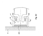
- the thermostatic valve which expands in functioning and which tends to dislodge or move aside the metal bracket of the case, now leans against the cylinder head since the stirrup is locked against the cylinder head without involving the projecting parts; these are only used to hold the stirrup for packaging and transport to assembly.
- Projecting parts also prevent movement of the bracket in the housing after its installation, under the effect of currents of water in the cooling circuit.
- thermoplastic material and / or thermosetting This allows to make the housing in thermoplastic material and / or thermosetting, simpler and more economical to manufacture than a box. In addition, it will be lighter.
- the arms of the stirrup are folded relative to the plane of the cup to extend by a part parallel to this plane and comprising the claws. So the cup with spring not only provides the support function for the spring of recall of the thermostatic valve but also that of the guide or holding the moving part of the valve.
- the raised part has an inverted T shape whose crosspiece constitutes the part around which the claws are crimped of a stirrup branch.
- the stirrup has two opposite branches and the housing, two parts in relief. In this case it is even possible to continue the claws with a double return so as to hang behind the returns of the sleeper.
- the stirrup has two branches opposite to the axis of the valve and the housing has two parts in relief in corresponding positions, the whole thus being symmetrical.
- the invention relates to an outlet box of water for an internal combustion engine.
- This case 1 shown in horizontal position, with its opening 2 facing upwards, is intended to be fixed against the opening of the cylinder head water circuit of a internal combustion, to allow the internal water circuit to the engine block to be connected in a controlled manner to the passing cooling circuit by the radiator and the circulation pump.
- the housing 1 includes a thermostatic valve 3 controlling opening or closing depending on the liquid temperature engine internal circuit cooling, to maintain this communication closed during the engine warm-up phase, so that the temperature rise is as rapid as possible, and open the communication only from a set target temperature by the control temperature of the integrated thermostatic capsule 31 in the thermostatic valve 3.
- This thermostatic valve of which only the end with the thermostatic capsule appears in the figure 1, is composed of two parts, a fixed part 32 and a mobile part 33 (see Figures 3A, 3B).
- the fixed part 32 rests against the bottom 11 of the housing and the movable part 33 is held in the housing 1 by a member retainer 4 with interposition of a return spring 5.
- the expansion of the thermostatic capsule 31 produces the displacement of the movable part 33 of the thermostatic valve against the action of the spring 5.
- the invention relates particularly to the attachment of the thermostatic valve 3 in case 1.
- the mounting on the cylinder head is done using screws passing through the screw holes 14.
- the housing 1 also includes various reinforcing elements and a liquid outlet 15 opening on the side, the arrival of liquid being through the opening 2 of the housing and a housing 16 receiving a temperature sensor 7 providing the temperature signal cooling water to the central control managing operation of the motor.
- FIG. 2 shows, in top view, the shape of the opening 81 of the cylinder head 8 of the engine against which the housing rests 1.
- This opening 81 comprises two support zones 82, 83 receiving, in compression, the retaining member 4 of the thermostatic valve 3 as will be explained later.
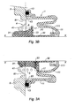
- FIGS. 3A, 3B and 4 show, more precisely, fixing the thermostatic valve 3 in the housing 1 using the retaining member 4.
- FIG 3A shows, in an axial half-section passing by the axis XX of the thermostatic valve 3, the water outlet housing 1 installed against the cylinder head 8 of the engine around the opening 81 of the circuit internal cooling.
- the thermostatic valve consists of two parts, one fixed 32 pressed against the bottom 11 of the housing 1 and the other 33, mobile, immersed in the coolant on the internal side of the cylinder head 8 of the engine through the opening 81 and into the volume which extends this opening in the water outlet housing 1.
- the movable part 33 of the thermostatic valve 3 is guided on the fixed part 32 in a manner not detailed here.
- the moving part 33 is held in preload by the return spring 5, by the stirrup-shaped retaining member 4 bearing in the mounting position against the cylinder head 8.
- the housing 1, shown in Figures 3A, 3B, in partial section only at the thermostatic valve 3 has a bottom 11 with a housing 111 receiving the fixed part 32 of the valve thermostatic; this rod-shaped part guides the mobile part 33 of the valve.
- the housing 1 is applied against the cylinder head 8 with interposition of the gasket 13.
- the housing fixing screws are not shown in this figure.
- FIG. 3A shows the closed thermostatic valve 3, the movable part 33 being applied against the surface 17 forming a seat valve in the bottom 11 of the housing.
- the bottom 11 of the housing has a cup shape to define the surface forming valve seat 17 and separating the volume (V) from this form of cup provided with the liquid outlet not shown in this figure.
- the volume (V) delimited between the bottom 11 in the form of a cup of the housing 1 and the movable part 33 of the valve 3 is placed in communication with the other part of the cooling circuit or internal part in the engine block.
- the closed position of the thermostatic valve 3 corresponds to a coolant temperature in which bathes the thermostatic capsule 31, which is not yet sufficient for expand this capsule and control the movement of the moving part 33 of the thermostatic valve to come into the position shown in the Figure 3B.
- thermostatic valve is held in place in the outlet box 2 via the shaped retaining member 4 bracket shown separately in Figure 4.
- This member 4 consists a spring cup 41, toroidal in shape, receiving one end in support of the return spring 5.
- This cup 41 surrounds the movable part 33 of the thermostatic valve and the guide as shown in Figures 3A, 3B.
- the cup 41 is provided with two arms 42 in positions opposed.
- Each arm 42 composed of an inclined part 421, rising relative to the cup 41, continues with a part 422 parallel to the cup and terminated by two claws 43 shown bent following a global section in the shape of a C.
- claws 43 curved are open as shown in broken lines for one (43A) of them, so as to separate their inner ends 431 by a distance (L) greater than the distance (1) shown in Full line.
- the two claws 43 of each branch 42 are intended to be crimped around a raised portion 18 located in an appropriate position of the housing as shown in Figures 1, 3A, 3B and especially 5A, 5B.
- the two raised portions 18 protrude from the wall of the housing 1 inwardly in opposite positions with respect to the axis XX of the thermostatic valve in the case of a two-leg caliper as in this example.
- the raised parts have a width L 0 slightly less than L.
- FIG. 5A shows, in front view, a part in relief 18 schematically in the shape of an inverted T, with a central branch 181 and a transverse branch 182 with returns 183.
Landscapes
- Engineering & Computer Science (AREA)
- Chemical & Material Sciences (AREA)
- Combustion & Propulsion (AREA)
- Mechanical Engineering (AREA)
- General Engineering & Computer Science (AREA)
- Temperature-Responsive Valves (AREA)
- Valve Housings (AREA)
- Check Valves (AREA)
- Self-Closing Valves And Venting Or Aerating Valves (AREA)
- Perforating, Stamping-Out Or Severing By Means Other Than Cutting (AREA)
- Output Control And Ontrol Of Special Type Engine (AREA)
- Other Liquid Machine Or Engine Such As Wave Power Use (AREA)
Abstract
Description
- le boítier comporte intérieurement au moins deux parties en relief dans des positions opposées par rapport à l'axe de la soupape thermostatique et
- l'organe de retenue en forme d'étrier comprend
- une coupelle à ressort formant la surface d'appui du ressort de rappel de la soupape thermostatique, et
- au moins deux bras opposés, prolongeant la coupelle, chaque bras étant muni de griffes serties autour de chacune des parties en relief.
- on réalise un boítier avec des parties en relief dans des positions opposées par rapport à l'axe XX de la soupape thermostatique,
- on réalise un organe de retenue en forme d'étrier comprenant une coupelle à ressort formant la surface d'appui du ressort de rappel de la soupape thermostatique, ayant des bras opposés, prolongeant la coupelle, chaque bras étant muni de griffes serties autour de chacune des parties en relief, les griffes étant écartées d'une distance supérieure L à la largeur L0 de chaque partie en relief,
- on installe, dans le boítier, une soupape thermostatique munie d'une capsule thermostatique et formée de deux parties dont l'une est fixe par rapport au boítier et l'autre, mobile, coopère avec une surface du boítier formant un siège de soupape et un ressort de rappel,
- on met en place l'organe de retenue sur le ressort de rappel et sur les parties en relief,
- on sertit les griffes de l'organe de retenue autour des parties en relief.
- la figure 1 est une vue en perspective d'un boítier de sortie d'eau selon l'invention, représenté avec son côté ouvert tourné vers le haut,
- la figure 2 est une vue de dessus de l'ouverture de la culasse sur laquelle se monte le boítier de la figure 1,
- les figures 3A, 3B sont des demi-coupes axiales partielles du boítier au niveau de la soupape thermostatique en position fermée et en position ouverte,
- la figure 4 est une vue en perspective de l'organe de retenue en forme d'étrier,
- les figures 5A, 5B sont des vues partielles à échelle agrandie du sertissage de l'étrier sur le boítier et la position d'appui du boiter contre la culasse,
- la figure 5C montre l'appui de l'étrier contre la culasse du moteur.
Claims (7)
- Boítier de sortie d'eau pour un moteur à combustion interne, destiné à être fixé sur l'ouverture du circuit d'eau de la culasse du moteur, comportantcaractérisé en ce queune entrée et une sortie reliées par un passage, équipé d'une soupape thermostatique (3) munie d'une capsule thermostatique (31) et formée de deux parties dont l'une (32) est fixe par rapport au boítier (1) et l'autre (33), mobile, coopère avec une surface du boítier formant un siège de soupape (17),
la partie mobile (33) fermant le passage s'appuyant contre le boítier par un organe de retenue (4) par l'intermédiaire d'un ressort de rappel (5), et son ouverture commandée par la dilatation de la capsule thermostatique (31) se faisant contre l'action du ressort (5),le boítier (1) comporte intérieurement au moins deux parties en relief (18) dans des positions opposées par rapport à l'axe (XX) de la soupape thermostatique (3) etl'organe de retenue (4) en forme d'étrier comprendune coupelle à ressort (41) formant la surface d'appui du ressort de rappel (5) de la soupape thermostatique (3), etau moins deux bras (42) opposés, prolongeant la coupelle (41), chaque bras (42) étant muni de griffes (43) serties autour de chacune des parties en relief (18). - Boítier de sortie d'eau selon la revendication 1,
caractérisé en ce que
la coupelle à ressort (41) est de forme torique entourant et guidant la partie mobile (33) de la soupape thermostatique (3). - Boítier de sortie d'eau selon la revendication 1,
caractérisé en ce que
les bras (42) de l'étrier (4) sont repliés (421) par rapport au plan de la coupelle (41) pour se prolonger par une partie (422) parallèle à ce plan et comportant les griffes (43). - Boítier de sortie d'eau selon la revendication 1,
caractérisé en ce que
la partie en relief (18) a une forme de T renversé dont la traverse (182) constitue la partie autour de laquelle sont serties les griffes (43) d'une branche (42) de l'étrier (4). - Boítier de sortie d'eau selon la revendication 1,
caractérisé en ce que
l'étrier (4) comporte deux branches (42) opposées et le boítier (1), deux parties en relief (18). - Procédé de réalisation d'un boítier de sortie d'eau selon l'une quelconque des revendications 1 à 5,
caractérisé en ce qu'on réalise un boítier (1) avec des parties en relief (18) dans des positions opposées par rapport à l'axe (XX) de la soupape thermostatique (3),on réalise un organe de retenue (4) en forme d'étrier comprenant une coupelle à ressort (41) formant la surface d'appui du ressort de rappel (5) de la soupape thermostatique (3), ayant des bras (42) opposés, prolongeant la coupelle (42), chaque bras (42) étant muni de griffes (43) serties autour de chacune des parties en relief (18), les griffes étant écartées d'une distance supérieure (L) à la largeur (L0) de chaque partie en relief (18),on installe, dans le boítier, une soupape thermostatique (3) munie d'une capsule thermostatique (31) et formée de deux parties dont l'une (32) est fixe par rapport au boítier (1) et l'autre (33), mobile, coopère avec une surface du boítier formant un siège de soupape (17) et un ressort de rappel (5),on met en place l'organe de retenue (4) sur le ressort de rappel (5) et sur les parties en relief (18),on sertit les griffes (43) de l'organe de retenue (4) autour des parties en relief (18). - Procédé selon la revendication 6,
caractérisé en ce qu'
on réalise le boítier par injection de matière plastique.
Applications Claiming Priority (2)
| Application Number | Priority Date | Filing Date | Title |
|---|---|---|---|
| FR0306134A FR2855214B1 (fr) | 2003-05-22 | 2003-05-22 | Boitier de sortie d'eau pour un moteur a combustion interne et procede de fabrication |
| FR0306134 | 2003-05-22 |
Publications (2)
| Publication Number | Publication Date |
|---|---|
| EP1479886A1 true EP1479886A1 (fr) | 2004-11-24 |
| EP1479886B1 EP1479886B1 (fr) | 2008-09-10 |
Family
ID=33042013
Family Applications (1)
| Application Number | Title | Priority Date | Filing Date |
|---|---|---|---|
| EP04102246A Expired - Lifetime EP1479886B1 (fr) | 2003-05-22 | 2004-05-21 | Boîtier de sortie d'eau pour un moteur à combustion interne et procédé de fabrication |
Country Status (4)
| Country | Link |
|---|---|
| EP (1) | EP1479886B1 (fr) |
| AT (1) | ATE408057T1 (fr) |
| DE (1) | DE602004016413D1 (fr) |
| FR (1) | FR2855214B1 (fr) |
Cited By (1)
| Publication number | Priority date | Publication date | Assignee | Title |
|---|---|---|---|---|
| FR2929646A1 (fr) * | 2008-04-08 | 2009-10-09 | Peugeot Citroen Automobiles Sa | Boitier de sortie d'eau de moteur a combustion interne |
Families Citing this family (1)
| Publication number | Priority date | Publication date | Assignee | Title |
|---|---|---|---|---|
| FR2890687B1 (fr) * | 2005-09-09 | 2008-02-08 | Renault Sas | Boitier de sortie d'eau pour la culasse d'un moteur a combustion interne |
Citations (2)
| Publication number | Priority date | Publication date | Assignee | Title |
|---|---|---|---|---|
| FR2667354A1 (fr) * | 1990-09-28 | 1992-04-03 | Jaeger | Soupape thermostatique pour circuit de refroidissement de moteur a combustion interne de vehicule automobile. |
| US5961039A (en) * | 1997-03-04 | 1999-10-05 | Vernet S.A. | Rapidly mounted thermostat |
-
2003
- 2003-05-22 FR FR0306134A patent/FR2855214B1/fr not_active Expired - Fee Related
-
2004
- 2004-05-21 EP EP04102246A patent/EP1479886B1/fr not_active Expired - Lifetime
- 2004-05-21 AT AT04102246T patent/ATE408057T1/de not_active IP Right Cessation
- 2004-05-21 DE DE602004016413T patent/DE602004016413D1/de not_active Expired - Lifetime
Patent Citations (2)
| Publication number | Priority date | Publication date | Assignee | Title |
|---|---|---|---|---|
| FR2667354A1 (fr) * | 1990-09-28 | 1992-04-03 | Jaeger | Soupape thermostatique pour circuit de refroidissement de moteur a combustion interne de vehicule automobile. |
| US5961039A (en) * | 1997-03-04 | 1999-10-05 | Vernet S.A. | Rapidly mounted thermostat |
Cited By (2)
| Publication number | Priority date | Publication date | Assignee | Title |
|---|---|---|---|---|
| FR2929646A1 (fr) * | 2008-04-08 | 2009-10-09 | Peugeot Citroen Automobiles Sa | Boitier de sortie d'eau de moteur a combustion interne |
| EP2108796A1 (fr) * | 2008-04-08 | 2009-10-14 | Peugeot Citroen Automobiles S.A. | Boitier de sortie d'eau de moteur a combustion interne |
Also Published As
| Publication number | Publication date |
|---|---|
| DE602004016413D1 (de) | 2008-10-23 |
| ATE408057T1 (de) | 2008-09-15 |
| FR2855214A1 (fr) | 2004-11-26 |
| FR2855214B1 (fr) | 2005-07-15 |
| EP1479886B1 (fr) | 2008-09-10 |
Similar Documents
| Publication | Publication Date | Title |
|---|---|---|
| EP1390639B1 (fr) | Support antivibratoire et procede de fabrication d'un tel support | |
| EP1375955A1 (fr) | Gaine pour ressort de suspension | |
| FR2812362A1 (fr) | Support antivibratoire hydraulique et son procede de fabrication | |
| FR2947331A1 (fr) | Echangeur de chaleur comprenant un faisceau de tubes avec au moins un tube inactif | |
| EP4100281A1 (fr) | Appui-tête de siège de véhicule automobile | |
| FR2889489A1 (fr) | Soupape de ventilation pour le reservoir a carburant dans des vehicules automobiles. | |
| EP1479886B1 (fr) | Boîtier de sortie d'eau pour un moteur à combustion interne et procédé de fabrication | |
| FR2841527A1 (fr) | Jeu de direction pour bicyclettes, cycles et similaires | |
| EP3423733B1 (fr) | Dispositif d'amortissement de vibrations entre un premier élément vibrant et un deuxième élément | |
| EP0800017B1 (fr) | Support antivibratoire hydraulique et sous-ensemble de véhicule automobile comportant un tel support | |
| EP1022487A1 (fr) | Tendeur comportant des moyens d'amortissement hydraulique et son procédé de fabrication | |
| FR2625284A1 (fr) | Valve de regulation de la pression a l'interieur d'un reservoir de carburant | |
| EP1650780B1 (fr) | Déclencheur électromagnétique et appareil de protection électronique le comportant | |
| FR2936581A1 (fr) | Valve pour amortisseur disposee entre une chambre inferieure et une chambre de compensation de l'amortisseur | |
| EP3863892B1 (fr) | Caisse de véhicule automobile équipé d'un module de haut-parleur | |
| EP1475268B1 (fr) | Agencement pour le positionnement et la fixation d'un élément d'équipement sur un véhicule automobile | |
| EP0863299B1 (fr) | Thermostat à montage rapide | |
| FR2557632A1 (fr) | Dispositif de refroidissement pour un moteur a combustion interne | |
| EP1715145B1 (fr) | Carter d'huile et moteur a combustion | |
| EP4370406A1 (fr) | Support d'aile avant d'un véhicule automobile | |
| EP0092469B1 (fr) | Dispositif de purge pour ensemble à cylindre et piston, et moteur de frein équipé d'un tel dispositif | |
| EP4313691B1 (fr) | Interface de fixation d'un d'equipement exterieur de vehicule | |
| FR2900452A1 (fr) | Assemblage d'un reservoir sur un support rigide | |
| FR3056173B1 (fr) | Compartiment moteur comprenant au moins un boitier pour composants electriques et/ou electroniques | |
| WO2008017774A1 (fr) | Ouvrant de vehicule automobile comprenant un raidisseur et vehicule muni un tel ouvrant |
Legal Events
| Date | Code | Title | Description |
|---|---|---|---|
| PUAI | Public reference made under article 153(3) epc to a published international application that has entered the european phase |
Free format text: ORIGINAL CODE: 0009012 |
|
| AK | Designated contracting states |
Kind code of ref document: A1 Designated state(s): AT BE BG CH CY CZ DE DK EE ES FI FR GB GR HU IE IT LI LU MC NL PL PT RO SE SI SK TR |
|
| AX | Request for extension of the european patent |
Extension state: AL HR LT LV MK |
|
| 17P | Request for examination filed |
Effective date: 20050118 |
|
| AKX | Designation fees paid |
Designated state(s): AT BE BG CH CY CZ DE DK EE ES FI FR GB GR HU IE IT LI LU MC NL PL PT RO SE SI SK TR |
|
| GRAP | Despatch of communication of intention to grant a patent |
Free format text: ORIGINAL CODE: EPIDOSNIGR1 |
|
| GRAS | Grant fee paid |
Free format text: ORIGINAL CODE: EPIDOSNIGR3 |
|
| GRAA | (expected) grant |
Free format text: ORIGINAL CODE: 0009210 |
|
| AK | Designated contracting states |
Kind code of ref document: B1 Designated state(s): AT BE BG CH CY CZ DE DK EE ES FI FR GB GR HU IE IT LI LU MC NL PL PT RO SE SI SK TR |
|
| REG | Reference to a national code |
Ref country code: GB Ref legal event code: FG4D Free format text: NOT ENGLISH |
|
| REG | Reference to a national code |
Ref country code: CH Ref legal event code: EP |
|
| REG | Reference to a national code |
Ref country code: IE Ref legal event code: FG4D Free format text: LANGUAGE OF EP DOCUMENT: FRENCH |
|
| REF | Corresponds to: |
Ref document number: 602004016413 Country of ref document: DE Date of ref document: 20081023 Kind code of ref document: P |
|
| PG25 | Lapsed in a contracting state [announced via postgrant information from national office to epo] |
Ref country code: AT Free format text: LAPSE BECAUSE OF FAILURE TO SUBMIT A TRANSLATION OF THE DESCRIPTION OR TO PAY THE FEE WITHIN THE PRESCRIBED TIME-LIMIT Effective date: 20080910 Ref country code: SI Free format text: LAPSE BECAUSE OF FAILURE TO SUBMIT A TRANSLATION OF THE DESCRIPTION OR TO PAY THE FEE WITHIN THE PRESCRIBED TIME-LIMIT Effective date: 20080910 Ref country code: FI Free format text: LAPSE BECAUSE OF FAILURE TO SUBMIT A TRANSLATION OF THE DESCRIPTION OR TO PAY THE FEE WITHIN THE PRESCRIBED TIME-LIMIT Effective date: 20080910 |
|
| NLV1 | Nl: lapsed or annulled due to failure to fulfill the requirements of art. 29p and 29m of the patents act | ||
| REG | Reference to a national code |
Ref country code: IE Ref legal event code: FD4D |
|
| PG25 | Lapsed in a contracting state [announced via postgrant information from national office to epo] |
Ref country code: IE Free format text: LAPSE BECAUSE OF FAILURE TO SUBMIT A TRANSLATION OF THE DESCRIPTION OR TO PAY THE FEE WITHIN THE PRESCRIBED TIME-LIMIT Effective date: 20080910 Ref country code: BG Free format text: LAPSE BECAUSE OF FAILURE TO SUBMIT A TRANSLATION OF THE DESCRIPTION OR TO PAY THE FEE WITHIN THE PRESCRIBED TIME-LIMIT Effective date: 20081210 Ref country code: ES Free format text: LAPSE BECAUSE OF FAILURE TO SUBMIT A TRANSLATION OF THE DESCRIPTION OR TO PAY THE FEE WITHIN THE PRESCRIBED TIME-LIMIT Effective date: 20081221 |
|
| PG25 | Lapsed in a contracting state [announced via postgrant information from national office to epo] |
Ref country code: RO Free format text: LAPSE BECAUSE OF FAILURE TO SUBMIT A TRANSLATION OF THE DESCRIPTION OR TO PAY THE FEE WITHIN THE PRESCRIBED TIME-LIMIT Effective date: 20080910 Ref country code: PT Free format text: LAPSE BECAUSE OF FAILURE TO SUBMIT A TRANSLATION OF THE DESCRIPTION OR TO PAY THE FEE WITHIN THE PRESCRIBED TIME-LIMIT Effective date: 20090210 Ref country code: NL Free format text: LAPSE BECAUSE OF FAILURE TO SUBMIT A TRANSLATION OF THE DESCRIPTION OR TO PAY THE FEE WITHIN THE PRESCRIBED TIME-LIMIT Effective date: 20080910 Ref country code: SK Free format text: LAPSE BECAUSE OF FAILURE TO SUBMIT A TRANSLATION OF THE DESCRIPTION OR TO PAY THE FEE WITHIN THE PRESCRIBED TIME-LIMIT Effective date: 20080910 Ref country code: CZ Free format text: LAPSE BECAUSE OF FAILURE TO SUBMIT A TRANSLATION OF THE DESCRIPTION OR TO PAY THE FEE WITHIN THE PRESCRIBED TIME-LIMIT Effective date: 20080910 |
|
| PLBE | No opposition filed within time limit |
Free format text: ORIGINAL CODE: 0009261 |
|
| STAA | Information on the status of an ep patent application or granted ep patent |
Free format text: STATUS: NO OPPOSITION FILED WITHIN TIME LIMIT |
|
| PG25 | Lapsed in a contracting state [announced via postgrant information from national office to epo] |
Ref country code: EE Free format text: LAPSE BECAUSE OF FAILURE TO SUBMIT A TRANSLATION OF THE DESCRIPTION OR TO PAY THE FEE WITHIN THE PRESCRIBED TIME-LIMIT Effective date: 20080910 Ref country code: DK Free format text: LAPSE BECAUSE OF FAILURE TO SUBMIT A TRANSLATION OF THE DESCRIPTION OR TO PAY THE FEE WITHIN THE PRESCRIBED TIME-LIMIT Effective date: 20080910 |
|
| 26N | No opposition filed |
Effective date: 20090611 |
|
| BERE | Be: lapsed |
Owner name: MANN + HUMMEL G.M.B.H. Effective date: 20090531 |
|
| PG25 | Lapsed in a contracting state [announced via postgrant information from national office to epo] |
Ref country code: MC Free format text: LAPSE BECAUSE OF NON-PAYMENT OF DUE FEES Effective date: 20090531 |
|
| REG | Reference to a national code |
Ref country code: CH Ref legal event code: PL |
|
| PG25 | Lapsed in a contracting state [announced via postgrant information from national office to epo] |
Ref country code: CH Free format text: LAPSE BECAUSE OF NON-PAYMENT OF DUE FEES Effective date: 20090531 Ref country code: LI Free format text: LAPSE BECAUSE OF NON-PAYMENT OF DUE FEES Effective date: 20090531 Ref country code: SE Free format text: LAPSE BECAUSE OF FAILURE TO SUBMIT A TRANSLATION OF THE DESCRIPTION OR TO PAY THE FEE WITHIN THE PRESCRIBED TIME-LIMIT Effective date: 20081210 |
|
| PG25 | Lapsed in a contracting state [announced via postgrant information from national office to epo] |
Ref country code: PL Free format text: LAPSE BECAUSE OF FAILURE TO SUBMIT A TRANSLATION OF THE DESCRIPTION OR TO PAY THE FEE WITHIN THE PRESCRIBED TIME-LIMIT Effective date: 20080910 |
|
| PG25 | Lapsed in a contracting state [announced via postgrant information from national office to epo] |
Ref country code: BE Free format text: LAPSE BECAUSE OF NON-PAYMENT OF DUE FEES Effective date: 20090531 |
|
| PG25 | Lapsed in a contracting state [announced via postgrant information from national office to epo] |
Ref country code: GR Free format text: LAPSE BECAUSE OF FAILURE TO SUBMIT A TRANSLATION OF THE DESCRIPTION OR TO PAY THE FEE WITHIN THE PRESCRIBED TIME-LIMIT Effective date: 20081211 |
|
| PG25 | Lapsed in a contracting state [announced via postgrant information from national office to epo] |
Ref country code: LU Free format text: LAPSE BECAUSE OF NON-PAYMENT OF DUE FEES Effective date: 20090521 |
|
| PG25 | Lapsed in a contracting state [announced via postgrant information from national office to epo] |
Ref country code: HU Free format text: LAPSE BECAUSE OF FAILURE TO SUBMIT A TRANSLATION OF THE DESCRIPTION OR TO PAY THE FEE WITHIN THE PRESCRIBED TIME-LIMIT Effective date: 20090311 |
|
| PG25 | Lapsed in a contracting state [announced via postgrant information from national office to epo] |
Ref country code: TR Free format text: LAPSE BECAUSE OF FAILURE TO SUBMIT A TRANSLATION OF THE DESCRIPTION OR TO PAY THE FEE WITHIN THE PRESCRIBED TIME-LIMIT Effective date: 20080910 |
|
| PG25 | Lapsed in a contracting state [announced via postgrant information from national office to epo] |
Ref country code: CY Free format text: LAPSE BECAUSE OF FAILURE TO SUBMIT A TRANSLATION OF THE DESCRIPTION OR TO PAY THE FEE WITHIN THE PRESCRIBED TIME-LIMIT Effective date: 20080910 |
|
| PGFP | Annual fee paid to national office [announced via postgrant information from national office to epo] |
Ref country code: GB Payment date: 20140521 Year of fee payment: 11 |
|
| PGFP | Annual fee paid to national office [announced via postgrant information from national office to epo] |
Ref country code: DE Payment date: 20140521 Year of fee payment: 11 Ref country code: IT Payment date: 20140527 Year of fee payment: 11 Ref country code: FR Payment date: 20140527 Year of fee payment: 11 |
|
| REG | Reference to a national code |
Ref country code: DE Ref legal event code: R119 Ref document number: 602004016413 Country of ref document: DE |
|
| GBPC | Gb: european patent ceased through non-payment of renewal fee |
Effective date: 20150521 |
|
| PG25 | Lapsed in a contracting state [announced via postgrant information from national office to epo] |
Ref country code: IT Free format text: LAPSE BECAUSE OF NON-PAYMENT OF DUE FEES Effective date: 20150521 |
|
| REG | Reference to a national code |
Ref country code: FR Ref legal event code: ST Effective date: 20160129 |
|
| PG25 | Lapsed in a contracting state [announced via postgrant information from national office to epo] |
Ref country code: DE Free format text: LAPSE BECAUSE OF NON-PAYMENT OF DUE FEES Effective date: 20151201 Ref country code: GB Free format text: LAPSE BECAUSE OF NON-PAYMENT OF DUE FEES Effective date: 20150521 |
|
| PG25 | Lapsed in a contracting state [announced via postgrant information from national office to epo] |
Ref country code: FR Free format text: LAPSE BECAUSE OF NON-PAYMENT OF DUE FEES Effective date: 20150601 |