EP1479605A2 - Helicopter - Google Patents
Helicopter Download PDFInfo
- Publication number
- EP1479605A2 EP1479605A2 EP04252900A EP04252900A EP1479605A2 EP 1479605 A2 EP1479605 A2 EP 1479605A2 EP 04252900 A EP04252900 A EP 04252900A EP 04252900 A EP04252900 A EP 04252900A EP 1479605 A2 EP1479605 A2 EP 1479605A2
- Authority
- EP
- European Patent Office
- Prior art keywords
- fuselage
- helicopter
- downwash
- flow control
- chemicals
- Prior art date
- Legal status (The legal status is an assumption and is not a legal conclusion. Google has not performed a legal analysis and makes no representation as to the accuracy of the status listed.)
- Granted
Links
- 239000000463 material Substances 0.000 claims description 4
- 239000002131 composite material Substances 0.000 claims description 3
- 239000002184 metal Substances 0.000 claims description 3
- 229910052751 metal Inorganic materials 0.000 claims description 3
- 229920003002 synthetic resin Polymers 0.000 claims description 3
- 239000000057 synthetic resin Substances 0.000 claims description 3
- 239000002023 wood Substances 0.000 claims description 3
- 239000000126 substance Substances 0.000 description 42
- 238000005507 spraying Methods 0.000 description 24
- 230000001788 irregular Effects 0.000 description 15
- 230000000694 effects Effects 0.000 description 7
- 238000005516 engineering process Methods 0.000 description 6
- 239000007921 spray Substances 0.000 description 6
- 230000002459 sustained effect Effects 0.000 description 5
- 230000037396 body weight Effects 0.000 description 2
- 230000008030 elimination Effects 0.000 description 2
- 238000003379 elimination reaction Methods 0.000 description 2
- 238000003912 environmental pollution Methods 0.000 description 2
- 239000003337 fertilizer Substances 0.000 description 2
- 238000010276 construction Methods 0.000 description 1
- 125000004122 cyclic group Chemical group 0.000 description 1
- 230000007423 decrease Effects 0.000 description 1
- 230000010006 flight Effects 0.000 description 1
- 150000002739 metals Chemical class 0.000 description 1
- 238000000034 method Methods 0.000 description 1
- 239000003595 mist Substances 0.000 description 1
Images


Classifications
-
- B—PERFORMING OPERATIONS; TRANSPORTING
- B64—AIRCRAFT; AVIATION; COSMONAUTICS
- B64D—EQUIPMENT FOR FITTING IN OR TO AIRCRAFT; FLIGHT SUITS; PARACHUTES; ARRANGEMENT OR MOUNTING OF POWER PLANTS OR PROPULSION TRANSMISSIONS IN AIRCRAFT
- B64D1/00—Dropping, ejecting, releasing or receiving articles, liquids, or the like, in flight
- B64D1/16—Dropping or releasing powdered, liquid, or gaseous matter, e.g. for fire-fighting
- B64D1/18—Dropping or releasing powdered, liquid, or gaseous matter, e.g. for fire-fighting by spraying, e.g. insecticides
-
- B—PERFORMING OPERATIONS; TRANSPORTING
- B64—AIRCRAFT; AVIATION; COSMONAUTICS
- B64C—AEROPLANES; HELICOPTERS
- B64C23/00—Influencing air flow over aircraft surfaces, not otherwise provided for
-
- B—PERFORMING OPERATIONS; TRANSPORTING
- B64—AIRCRAFT; AVIATION; COSMONAUTICS
- B64C—AEROPLANES; HELICOPTERS
- B64C5/00—Stabilising surfaces
- B64C5/10—Stabilising surfaces adjustable
- B64C5/12—Stabilising surfaces adjustable for retraction against or within fuselage or nacelle
-
- B—PERFORMING OPERATIONS; TRANSPORTING
- B64—AIRCRAFT; AVIATION; COSMONAUTICS
- B64C—AEROPLANES; HELICOPTERS
- B64C27/00—Rotorcraft; Rotors peculiar thereto
- B64C27/04—Helicopters
Definitions
- the invention relates to a helicopter, and more particularly to a helicopter having a downwash flow control function.
- Spraying of chemicals or fertilizers using a helicopter has been put into practice in an agricultural field or the like.
- the helicopter In such spraying operations, the helicopter generally maintains low speed almost hovering at the height of having high influence of ground effect so as to adhere the chemicals in mist even to the backside of leaves of crops to be sprayed, effectively utilizing the downwash generated by the rotation of a rotor of the helicopter.
- FIG. 6 shows a downwash flow generated by the rotor rotation of the helicopter. It has been known that, as shown in FIG. 6, the downwash D flows downward at high speed along fuselage side surfaces 110 of a helicopter 100 and separates at a fuselage lower surface 120 to produce an irregular air current C. Therefore, when spraying nozzles are disposed at the lower surface 120, the irregular air current C causes lots of chemicals to adhere to the lower surface 120, and the adhered chemicals fall as droplets or part of chemicals is sometimes not sprayed, resulting in lower spraying efficiency. In order to avoid this, nozzles 200 are often disposed apart from a fuselage 101 of the helicopter 100 as shown in FIG. 7.
- the helicopter When spraying chemicals or the like, the helicopter keeps at a low speed in almost hovering flight at the height of having high influence of ground effect as described before, and therefore the generation of an irregular air current under the fuselage due to the downwash leads to a problem of impairing the stability of the body during flight, and reducing controllability.
- An object of the invention is to provide a helicopter for use in spraying chemicals or the like, which improves spraying efficiency by preventing the chemicals from adhering to the lower surface of a fuselage with effective use of a downwash, and improves stability and controllability of the body during flight such as a spraying flight in which a low speed in almost hovering flight is sustained at the height of having high influence of ground effect.
- a helicopter comprises: a flow control device provided at one of a lower portion of a side surface of a fuselage and a portion on a lower surface of the fuselage near the side surface and extending downward.
- the helicopter of the first aspect of the invention with the flow control device provided, extending downward, at one of the lower portion of the fuselage side surface and the portion on the lower surface of the fuselage near the side surface, the downwash flowing along the fuselage side surfaces is guided outward apart from the fuselage, maintaining a steady flow. Therefore, the downwash reaches the ground surface as a steady flow irrespective of the fuselage, allowing chemicals or the like to be effectively diffused when the helicopter sprays the chemicals or the like.
- the flow control device also prevents the downwash from flowing into the under side of the fuselage, which suppresses generation of irregular air current under the fuselage.
- This air current prevents the chemicals from adhering to the fuselage lower surface when the helicopter sprays the chemicals or the like, to thereby improve spraying efficiency and also eliminate removing work of the chemicals adhering to the fuselage lower surface.
- the flow control device suppresses the generation of irregular air current under the fuselage, the body posture can be stabilized, and further body controllability can be remarkably improved during the flight such as the spraying flight in which low speed almost hovering is sustained at the height of having high influence of ground effect.
- a helicopter comprises: a flow control device provided at one of a lower portion of a side surface of a fuselage and a portion on a lower surface of the fuselage near the side surface, for guiding a downwash flowing along the side surface of the fuselage to flow apart from the fuselage.
- the downwash flowing along the fuselage side surfaces is guided outward apart from the fuselage. Accordingly, the downwash can generate a circulating flow at the sides of the fuselage, allowing chemicals or the like to be effectively diffused when the helicopter sprays the chemicals or the like.
- the flow control device is provided at one of the lower portion of the fuselage side surface and the portion on the lower surface of the fuselage near the side surface so that the downwash flowing along the fuselage side surfaces is guided outward apart from the fuselage, which prevents the downwash from flowing into the under side of the fuselage.
- the flow control device suppresses the generation of irregular air current under the fuselage, the body posture can be stabilized, and further body controllability can be remarkably improved during the flight such as the spraying flight in which low speed almost hovering is sustained at the height of having high influence of ground effect.
- a helicopter comprises: a projection member provided at one of a lower portion of a side surface of a fuselage and a portion on a lower surface of the fuselage near the side surface and projecting downward.
- the projecting member is provided projecting downward at one of the lower portion of the fuselage side surface and the portion on the lower surface of the fuselage near the side surface, the downwash flowing along the fuselage side surfaces is prevented from flowing into the under side of the fuselage. This suppresses generation of irregular air current under the fuselage. Accordingly, when the helicopter sprays the chemicals or the like, the chemicals are prevented from adhering to the fuselage lower surface, resulting in improvement of spraying efficiency and also elimination of removing work of the chemicals adhering to the fuselage lower surface.
- the projecting member suppresses the generation of irregular air current under the fuselage, the body posture can be stabilized, and further body controllability can be remarkably improved during the flight such as the spraying flight in which low speed almost hovering is sustained at the height of having high influence of ground effect.
- the helicopter further comprises a flow channel within the fuselage for guiding a downwash on an upper side of the fuselage to a lower side of the fuselage.
- the flow channels are provided within the fuselage for guiding the downwash on the upper side of the fuselage to the lower side of the fuselage, the air is replenished to the lower space of the fuselage, which always keeps the pressure of the lower space positive.
- This positive pressure securely prevents the downwash flowing along the fuselage side surfaces from flowing into the lower side of the fuselage, thereby effectively suppressing the generation of irregular air current at the lower side of the fuselage.
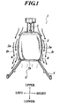
- the helicopter 1 comprises a fuselage 2, a main rotor 4 attached to the upper portion of the fuselage 2 via a rotor shaft 3, skids 5 attached to the lower portion of the fuselage 2, a tail boom 6 coupled to the fuselage 2 at its rear side, a tail rotor 7 attached to a rear tip of the tail boom 6, flow control plates 8 mounted on the lower portions of both side surfaces 2a of the fuselage 2, and the like (see FIGS. 1 and 2).
- the helicopter 1 is used for spraying chemicals or fertilizers, and provided with spraying nozzles (not shown) on a lower surface 2b of the fuselage 2.
- a pilot's seat Installed inside the fuselage 2 are a pilot's seat, a cargo compartment, and further an engine for driving the main rotor 4 and the tail rotor 7, and control devices such as a cyclic stick, a collective stick and a pedal. Rotation of the main rotor 4 driven by the engine generates a downwash D as shown in FIG. 1.
- the flow control plates 8 are one example of a flow control device and a projecting member of the invention, and attached to the lower portions of both side surfaces 2a of the fuselage 2, projecting downward on a slant (right-side downward and left-side downward in FIG.1). That is, the flow control plates 8 look truncated chevron shaped when viewed from the front of the helicopter 1 (see FIG. 1).
- the flow control plates 8 guide the downwash D, which flows along both side surfaces 2a, right-side downward and left-side downward of FIG.1, respectively, so as to flow apart from the fuselage 2, preventing the downwash D from flowing into a lower space U of the fuselage 2.
- the flow control plates 8 are provided at the lower portions of both side surfaces 2a of the fuselage 2, extending to a front-and-rear direction.
- the plates 8 may be provided, extending to the front-and-rear direction, along almost the entire length of the lower portions of both side surfaces 2a (see FIG. 2), or dividedly provided at front portions B, center portions C and rear portions D (see FIG. 3).
- the plates 8 can be made of various metals, various synthetic resins, various rubber material, wood, and composite material composed of these materials.
- each flow control plate 8 (length in a direction normal to the fuselage side surface 2a) is set to a larger value than the thickness of a boundary layer on the side surface 2a. While the downwash D flows along both side surfaces 2a, it has higher flowing speed in the area apart from the side surface 2a by a certain distance (the thickness of the boundary layer) under less influence of viscosity. On the other hand, the downwash D flows at low speed in the area close to the side surface 2a (in the boundary layer) under the influence of viscosity. Therefore, in order to control the downwash D by the flow control plates 8, the height of the plate 8 needs to be set to a larger value than the thickness of the boundary layer. In the embodiment, the height of the plate 8 is set to about 40 mm.
- the downwash D flowing along both side surfaces 2a is guided, by the flow control plates 8 mounted at lower portions of both side surfaces 2a, right-side downward or left-side downward of FIG. 1 so as to flow apart from both side surfaces 2a, while keeping a steady flow. Accordingly, the downwash D reaches the ground surface as a steady flow irrespective of the fuselage 2, allowing the chemicals to adhere even to the back of leaves of crops to be sprayed.
- the flow control plates 8 are mounted at the lower portions of both side surfaces 2a so as to guide the downwash D outward apart from the fuselage 2, which prevents the downwash D from flowing into a lower space U of the fuselage 2 (see FIG. 1). This prevents generation of an irregular air current at the lower space U of the fuselage 2, thereby preventing chemicals from adhering to the lower surface 2b of the fuselage 2. This improves spraying efficiency and also eliminates the work of removing chemicals adhering to the lower surface 2b of the fuselage 2.
- the flow control plates 8 mounted on the helicopter 1 of the embodiment prevent chemicals from adhering to the lower surface 2b of the fuselage 2, avoiding the environmental pollution caused by the removal of the chemicals.
- the helicopter 1 of the embodiment is provided with the flow control plates 8, which prevents chemicals from adhering to the lower surface 2b of the fuselage 2, allowing the nozzles, to be disposed on the lower surface 2b of the fuselage 2. This disposition allows a reduction of body weight and also improves spaying efficiency with stable supply of chemicals or the like.
- the helicopter 1 of the embodiment is provided with the flow control plates 8 at the lower portions of both side surfaces 2a of the fuselage 2, which suppresses the generation of irregular air currents at the lower space U of the fuselage 2. Therefore, the body posture can be stabilized and, further, body controllability can be remarkably improved during the flight such as the spraying flight in which low speed in almost hovering flight is sustained at the height of having high influence of ground effect.
- FIGS. 4 and 5 A description will be given of the structure of a helicopter 10 according to a second embodiment with reference to FIGS. 4 and 5.
- the helicopter 10 of the embodiment is such that particular flow channels are provided within the fuselage 2 of the helicopter 1 according to the first embodiment, each flow channel guiding the downwash D on an upper side of the fuselage 2 to the lower space U of the fuselage 2. Therefore, the same elements as corresponding elements of the helicopter 1 are designated by the same reference numerals.
- an upper opening portion 9a and a lower opening portion 9b there are provided at the front of the fuselage 2 of the helicopter 10 an upper opening portion 9a and a lower opening portion 9b, and at a front side within the fuselage 2 a hollow portion 9c (see FIGS. 4 and 5).
- These upper opening portion 9a, lower opening portion 9b and hollow portion 9c form a flow channel in the present invention.
- the downwash D generated by the rotation of the main rotor 4 of the helicopter 10 flows from the upper opening portion 9a into the hollow portion 9c of the fuselage 2, and flows out from the lower opening portion 9b to the lower space U.
- an upper opening portion 9d and a lower opening portion 9e there are also provided at the rear of the fuselage 2 of the helicopter 10 an upper opening portion 9d and a lower opening portion 9e, and at a rear side within the fuselage 2 a hollow portion 9f (see FIG. 5).
- These upper opening portion 9d, hollow portion 9f and lower opening portion 9e form another flow channel in the present invention.
- the downwash D generated by the rotation of the main rotor 4 flows from the upper opening portion 9d into the hollow portion 9f, and flows out from the lower opening portion 9e to the lower space U.
- the downwash D over the fuselage 2 can be guided to the lower space U through the flow channels within the fuselage 2, the channels being formed by the upper opening portions 9a and 9d of the fuselage 2, the hollow portions 9c and 9f within the fuselage 2, and the lower opening portions 9b and 9e of the fuselage 2, respectively, (see FIGS. 4 and 5). Therefore, the air is replenished to the lower space U of the fuselage 2, which always keeps the pressure of the lower space U positive. This positive pressure securely prevents the downwash D, which flows along both side surfaces 2a and the flow control plates 8, from flowing into the lower space U, thereby effectively suppressing the generation of irregular air currents in the lower space U.
- the flow control plates 8 in the embodiments are attached in a truncated chevron shape when viewed from the front (extending right-side downward or left-side downward in FIGS. 1 and 4), but the attaching angle of the flow control plate 8 with respect to the side surface 2a is preferably changeable. Further, flow control plates 8 which are extendable and retractable may be provided, the plates 8 may be extended outward from the side surfaces 2a during spraying chemicals, and retracted into the fuselage 2 during normal flights.
- the flow control plates 8 are provided symmetrical to each other at both side surfaces 2a (see FIGS. 1 and 4), but they may not be always symmetrical. Especially, when flowing directions of the downwash D considerably differ between the right side and left side of the fuselage 2 depending on rotating directions of the main rotor 4, the flow control plates 8 may be preferably provided depending on the flowing directions of the downwash D.
- the flow control plates 8 in the embodiments are mounted exemplarily at the lower portions of both side surfaces 2a (see FIGS. 1 and 4), but may be mounted at sides of the lower surface 2b of the fuselage 2 (neighboring the side surfaces 2a) extending downward on a slant (right-side downward and left-side downward in FIGS. 1 and 4). Even with the flow control plates 8 thus mounted at the sides of the lower surface 2b of the fuselage 2, the downwash D flowing along the side surfaces 2a can be guided outward apart from the fuselage 2.
- the flow control plates 8 in the embodiments are employed as the flow control device and the projecting member, but a block type member may be employed as the flow control device and the projecting member instead of the plate type member. That is, if a structure has a function of guiding the downwash D to flow along the side surfaces 2a outward apart from the fuselage 2, a structure of any kind can be employed as the flow control device and the projecting member.
- the flow channels are formed within the fuselage 2 with the opening portions provided at the upper and lower portions of the fuselage 2 so as to pass through the hollow portions, it is not always necessary to provide walls or the like along the flow channels.
- the shape of the flow channels (areas/shapes of the upper opening portions 9a, 9d and the lower opening portions 9b, 9e, and volumes/shapes of the hollow portions 9c, 9f) may also be properly decided according to flowing speed and the like of the downwash D.
- the flow control device provided, extending downward, at one of the lower portion of the fuselage side surface and the portion on the lower surface of the fuselage near the side surface, the downwash flowing along the fuselage side surfaces is guided outward apart from the fuselage, maintaining a steady flow. Therefore, it can effectively utilize the downwash when diffusing chemicals or the like by the helicopter.
- the flow control device or the projection member prevents the downwash from flowing into the under side of the fuselage, which suppresses generation of irregular air current under the fuselage.
- This air current prevents the chemicals from adhering to the fuselage lower surface when the helicopter sprays the chemicals or the like, to thereby improve spraying efficiency and also eliminate removing work of the chemicals adhering to the fuselage lower surface.
Landscapes
- Engineering & Computer Science (AREA)
- Aviation & Aerospace Engineering (AREA)
- Life Sciences & Earth Sciences (AREA)
- Pest Control & Pesticides (AREA)
- Catching Or Destruction (AREA)
- Toys (AREA)
Abstract
Description
- The invention relates to a helicopter, and more particularly to a helicopter having a downwash flow control function.
- Spraying of chemicals or fertilizers using a helicopter has been put into practice in an agricultural field or the like. In such spraying operations, the helicopter generally maintains low speed almost hovering at the height of having high influence of ground effect so as to adhere the chemicals in mist even to the backside of leaves of crops to be sprayed, effectively utilizing the downwash generated by the rotation of a rotor of the helicopter.
- FIG. 6 shows a downwash flow generated by the rotor rotation of the helicopter. It has been known that, as shown in FIG. 6, the downwash D flows downward at high speed along
fuselage side surfaces 110 of ahelicopter 100 and separates at a fuselagelower surface 120 to produce an irregular air current C. Therefore, when spraying nozzles are disposed at thelower surface 120, the irregular air current C causes lots of chemicals to adhere to thelower surface 120, and the adhered chemicals fall as droplets or part of chemicals is sometimes not sprayed, resulting in lower spraying efficiency. In order to avoid this,nozzles 200 are often disposed apart from afuselage 101 of thehelicopter 100 as shown in FIG. 7. - Recently, various kinds of technologies have been proposed for controlling such downwash flow. For instance, such a technology is disclosed that, by providing a flow control device (a forming member, a drift plate, a cover, etc.) at the upper part of a helicopter fuselage, a rescuer or a worker positioned under the fuselage can avoid being directly exposed to a strong downwash (see, for example, JP-Tokukaihei-7-47998A).
- When spraying chemicals using a helicopter, it is effective to diffuse the chemicals by the downwash generated by the rotor rotation of the helicopter. However, the technology described in above JP-Tokukaihei-7-47998A would lead to a problem that it cannot effectively utilize the downwash.
- If the technology that uses nozzles disposed apart from, the helicopter fuselage is adopted (see FIG. 7), supporting members having nozzles mounted thereon need to be long in order to avoid adhesion of chemicals to the lower part of the fuselage due to the downwash, resulting in weight increase of the helicopter. Accordingly, it has long been desired to develop a new technology for reducing the weight of a helicopter and simultaneously for improving spraying efficiency.
- When spraying chemicals or the like, the helicopter keeps at a low speed in almost hovering flight at the height of having high influence of ground effect as described before, and therefore the generation of an irregular air current under the fuselage due to the downwash leads to a problem of impairing the stability of the body during flight, and reducing controllability.
- An object of the invention is to provide a helicopter for use in spraying chemicals or the like, which improves spraying efficiency by preventing the chemicals from adhering to the lower surface of a fuselage with effective use of a downwash, and improves stability and controllability of the body during flight such as a spraying flight in which a low speed in almost hovering flight is sustained at the height of having high influence of ground effect.
- In accordance with a first aspect of the present invention, a helicopter comprises: a flow control device provided at one of a lower portion of a side surface of a fuselage and a portion on a lower surface of the fuselage near the side surface and extending downward.
- According to the helicopter of the first aspect of the invention, with the flow control device provided, extending downward, at one of the lower portion of the fuselage side surface and the portion on the lower surface of the fuselage near the side surface, the downwash flowing along the fuselage side surfaces is guided outward apart from the fuselage, maintaining a steady flow. Therefore, the downwash reaches the ground surface as a steady flow irrespective of the fuselage, allowing chemicals or the like to be effectively diffused when the helicopter sprays the chemicals or the like.
- Also, according to the helicopter of the first aspect of the invention, the flow control device also prevents the downwash from flowing into the under side of the fuselage, which suppresses generation of irregular air current under the fuselage. This air current prevents the chemicals from adhering to the fuselage lower surface when the helicopter sprays the chemicals or the like, to thereby improve spraying efficiency and also eliminate removing work of the chemicals adhering to the fuselage lower surface.
- Further, according to the helicopter of the first aspect of the invention, since the flow control device suppresses the generation of irregular air current under the fuselage, the body posture can be stabilized, and further body controllability can be remarkably improved during the flight such as the spraying flight in which low speed almost hovering is sustained at the height of having high influence of ground effect.
- In accordance with a second aspect of the present invention, a helicopter comprises: a flow control device provided at one of a lower portion of a side surface of a fuselage and a portion on a lower surface of the fuselage near the side surface, for guiding a downwash flowing along the side surface of the fuselage to flow apart from the fuselage.
- According to the helicopter of the second aspect of the invention, with the flow control device provided, extending downward, at one of the lower portion of the fuselage side surface and the portion on the lower surface near the side surface of the fuselage, the downwash flowing along the fuselage side surfaces is guided outward apart from the fuselage. Accordingly, the downwash can generate a circulating flow at the sides of the fuselage, allowing chemicals or the like to be effectively diffused when the helicopter sprays the chemicals or the like.
- Also, according to the helicopter of the second aspect of the invention, the flow control device is provided at one of the lower portion of the fuselage side surface and the portion on the lower surface of the fuselage near the side surface so that the downwash flowing along the fuselage side surfaces is guided outward apart from the fuselage, which prevents the downwash from flowing into the under side of the fuselage. This suppresses generation of irregular air current under the fuselage. Accordingly, when the helicopter sprays chemicals or the like, the chemicals are prevented from adhering to the fuselage lower surface, resulting in improvement of spraying efficiency and also elimination of removing work of the chemicals adhering to the fuselage lower surface.
- Further, according to the helicopter of the second aspect of the invention, Since the flow control device suppresses the generation of irregular air current under the fuselage, the body posture can be stabilized, and further body controllability can be remarkably improved during the flight such as the spraying flight in which low speed almost hovering is sustained at the height of having high influence of ground effect.
- In accordance with a third aspect of the invention, a helicopter comprises: a projection member provided at one of a lower portion of a side surface of a fuselage and a portion on a lower surface of the fuselage near the side surface and projecting downward.
- According to the helicopter of the third aspect of the invention, since the projecting member is provided projecting downward at one of the lower portion of the fuselage side surface and the portion on the lower surface of the fuselage near the side surface, the downwash flowing along the fuselage side surfaces is prevented from flowing into the under side of the fuselage. This suppresses generation of irregular air current under the fuselage. Accordingly, when the helicopter sprays the chemicals or the like, the chemicals are prevented from adhering to the fuselage lower surface, resulting in improvement of spraying efficiency and also elimination of removing work of the chemicals adhering to the fuselage lower surface.
- Also, according to the helicopter of the third aspect of the invention, since the projecting member suppresses the generation of irregular air current under the fuselage, the body posture can be stabilized, and further body controllability can be remarkably improved during the flight such as the spraying flight in which low speed almost hovering is sustained at the height of having high influence of ground effect.
- Preferably, the helicopter further comprises a flow channel within the fuselage for guiding a downwash on an upper side of the fuselage to a lower side of the fuselage.
- Accordingly, since the flow channels are provided within the fuselage for guiding the downwash on the upper side of the fuselage to the lower side of the fuselage, the air is replenished to the lower space of the fuselage, which always keeps the pressure of the lower space positive. This positive pressure securely prevents the downwash flowing along the fuselage side surfaces from flowing into the lower side of the fuselage, thereby effectively suppressing the generation of irregular air current at the lower side of the fuselage.
- By way of example only, specific embodiments of the present invention will now be described with reference to the accompanying drawings, in which:
- FIG. 1 is a front view of a helicopter according to a first embodiment of the present invention;
- FIG. 2 is a side view of the helicopter shown in FIG. 1 (with a flow control plate provided at an almost entire length of a lower portion of a fuselage side surface);
- FIG. 3 is a side view of the helicopter shown in FIG. 1 (with divided flow control plates provided separately at the lower portion of the fuselage side surface);
- FIG. 4 is a front view of a helicopter according to a second embodiment of the present invention;
- FIG. 5 is a sectional side view of the helicopter shown in FIG. 4.
- FIG. 6 is a front view of a helicopter of an earlier technique; and
- FIG. 7 is a front view of the helicopter of FIG. 6 provided with nozzles for spraying chemicals.
-
- Embodiments of the invention will be described in detail with reference to the drawings.
- Referring to FIGS. 1 to 3, a construction of a
helicopter 1 according to the first embodiment will be explained. Thehelicopter 1 comprises afuselage 2, amain rotor 4 attached to the upper portion of thefuselage 2 via arotor shaft 3,skids 5 attached to the lower portion of thefuselage 2, atail boom 6 coupled to thefuselage 2 at its rear side, atail rotor 7 attached to a rear tip of thetail boom 6, flow control plates 8 mounted on the lower portions of bothside surfaces 2a of thefuselage 2, and the like (see FIGS. 1 and 2). Thehelicopter 1 is used for spraying chemicals or fertilizers, and provided with spraying nozzles (not shown) on alower surface 2b of thefuselage 2. - Installed inside the
fuselage 2 are a pilot's seat, a cargo compartment, and further an engine for driving themain rotor 4 and thetail rotor 7, and control devices such as a cyclic stick, a collective stick and a pedal. Rotation of themain rotor 4 driven by the engine generates a downwash D as shown in FIG. 1. - The flow control plates 8 are one example of a flow control device and a projecting member of the invention, and attached to the lower portions of both
side surfaces 2a of thefuselage 2, projecting downward on a slant (right-side downward and left-side downward in FIG.1). That is, the flow control plates 8 look truncated chevron shaped when viewed from the front of the helicopter 1 (see FIG. 1). The flow control plates 8 guide the downwash D, which flows along bothside surfaces 2a, right-side downward and left-side downward of FIG.1, respectively, so as to flow apart from thefuselage 2, preventing the downwash D from flowing into a lower space U of thefuselage 2. - The flow control plates 8 are provided at the lower portions of both
side surfaces 2a of thefuselage 2, extending to a front-and-rear direction. The plates 8 may be provided, extending to the front-and-rear direction, along almost the entire length of the lower portions of bothside surfaces 2a (see FIG. 2), or dividedly provided at front portions B, center portions C and rear portions D (see FIG. 3). The plates 8 can be made of various metals, various synthetic resins, various rubber material, wood, and composite material composed of these materials. - The height of each flow control plate 8 (length in a direction normal to the
fuselage side surface 2a) is set to a larger value than the thickness of a boundary layer on theside surface 2a. While the downwash D flows along bothside surfaces 2a, it has higher flowing speed in the area apart from theside surface 2a by a certain distance (the thickness of the boundary layer) under less influence of viscosity. On the other hand, the downwash D flows at low speed in the area close to theside surface 2a (in the boundary layer) under the influence of viscosity. Therefore, in order to control the downwash D by the flow control plates 8, the height of the plate 8 needs to be set to a larger value than the thickness of the boundary layer. In the embodiment, the height of the plate 8 is set to about 40 mm. - In the
helicopter 1 of the embodiment, the downwash D flowing along bothside surfaces 2a is guided, by the flow control plates 8 mounted at lower portions of bothside surfaces 2a, right-side downward or left-side downward of FIG. 1 so as to flow apart from bothside surfaces 2a, while keeping a steady flow. Accordingly, the downwash D reaches the ground surface as a steady flow irrespective of thefuselage 2, allowing the chemicals to adhere even to the back of leaves of crops to be sprayed. - In the
helicopter 1 of the embodiment, the flow control plates 8 are mounted at the lower portions of bothside surfaces 2a so as to guide the downwash D outward apart from thefuselage 2, which prevents the downwash D from flowing into a lower space U of the fuselage 2 (see FIG. 1). This prevents generation of an irregular air current at the lower space U of thefuselage 2, thereby preventing chemicals from adhering to thelower surface 2b of thefuselage 2. This improves spraying efficiency and also eliminates the work of removing chemicals adhering to thelower surface 2b of thefuselage 2. - When chemicals adhere to the fuselage
lower surface 2b, the chemicals are condensed to a high concentration When the highly concentrated chemicals are removed at a different place other than the sprayed place, it sometimes causes environmental pollution. However, the flow control plates 8 mounted on thehelicopter 1 of the embodiment prevent chemicals from adhering to thelower surface 2b of thefuselage 2, avoiding the environmental pollution caused by the removal of the chemicals. - If the technology that uses nozzles disposed apart from the
helicopter fuselage 2 is adopted (see FIG. 7), supporting members having nozzles mounted thereon need to be long, which increases body weight and sometimes decreases spraying efficiency due to disorderly supply of chemicals to the nozzles. On the other hand, thehelicopter 1 of the embodiment is provided with the flow control plates 8, which prevents chemicals from adhering to thelower surface 2b of thefuselage 2, allowing the nozzles, to be disposed on thelower surface 2b of thefuselage 2. This disposition allows a reduction of body weight and also improves spaying efficiency with stable supply of chemicals or the like. - The
helicopter 1 of the embodiment is provided with the flow control plates 8 at the lower portions of bothside surfaces 2a of thefuselage 2, which suppresses the generation of irregular air currents at the lower space U of thefuselage 2. Therefore, the body posture can be stabilized and, further, body controllability can be remarkably improved during the flight such as the spraying flight in which low speed in almost hovering flight is sustained at the height of having high influence of ground effect. - A description will be given of the structure of a
helicopter 10 according to a second embodiment with reference to FIGS. 4 and 5. Thehelicopter 10 of the embodiment is such that particular flow channels are provided within thefuselage 2 of thehelicopter 1 according to the first embodiment, each flow channel guiding the downwash D on an upper side of thefuselage 2 to the lower space U of thefuselage 2. Therefore, the same elements as corresponding elements of thehelicopter 1 are designated by the same reference numerals. - There are provided at the front of the
fuselage 2 of thehelicopter 10 anupper opening portion 9a and alower opening portion 9b, and at a front side within thefuselage 2 ahollow portion 9c (see FIGS. 4 and 5). Theseupper opening portion 9a,lower opening portion 9b andhollow portion 9c form a flow channel in the present invention. The downwash D generated by the rotation of themain rotor 4 of thehelicopter 10 flows from theupper opening portion 9a into thehollow portion 9c of thefuselage 2, and flows out from thelower opening portion 9b to the lower space U. - There are also provided at the rear of the
fuselage 2 of thehelicopter 10 an upper opening portion 9d and a lower opening portion 9e, and at a rear side within thefuselage 2 ahollow portion 9f (see FIG. 5). These upper opening portion 9d,hollow portion 9f and lower opening portion 9e form another flow channel in the present invention. The downwash D generated by the rotation of themain rotor 4 flows from the upper opening portion 9d into thehollow portion 9f, and flows out from the lower opening portion 9e to the lower space U. - In the
helicopter 10 of the embodiment, the downwash D over thefuselage 2 can be guided to the lower space U through the flow channels within thefuselage 2, the channels being formed by theupper opening portions 9a and 9d of thefuselage 2, thehollow portions fuselage 2, and thelower opening portions 9b and 9e of thefuselage 2, respectively, (see FIGS. 4 and 5). Therefore, the air is replenished to the lower space U of thefuselage 2, which always keeps the pressure of the lower space U positive. This positive pressure securely prevents the downwash D, which flows along bothside surfaces 2a and the flow control plates 8, from flowing into the lower space U, thereby effectively suppressing the generation of irregular air currents in the lower space U. - The flow control plates 8 in the embodiments are attached in a truncated chevron shape when viewed from the front (extending right-side downward or left-side downward in FIGS. 1 and 4), but the attaching angle of the flow control plate 8 with respect to the
side surface 2a is preferably changeable. Further, flow control plates 8 which are extendable and retractable may be provided, the plates 8 may be extended outward from the side surfaces 2a during spraying chemicals, and retracted into thefuselage 2 during normal flights. - In the embodiments, the flow control plates 8 are provided symmetrical to each other at both
side surfaces 2a (see FIGS. 1 and 4), but they may not be always symmetrical. Especially, when flowing directions of the downwash D considerably differ between the right side and left side of thefuselage 2 depending on rotating directions of themain rotor 4, the flow control plates 8 may be preferably provided depending on the flowing directions of the downwash D. - Further, the flow control plates 8 in the embodiments are mounted exemplarily at the lower portions of both
side surfaces 2a (see FIGS. 1 and 4), but may be mounted at sides of thelower surface 2b of the fuselage 2 (neighboring the side surfaces 2a) extending downward on a slant (right-side downward and left-side downward in FIGS. 1 and 4). Even with the flow control plates 8 thus mounted at the sides of thelower surface 2b of thefuselage 2, the downwash D flowing along the side surfaces 2a can be guided outward apart from thefuselage 2. - The flow control plates 8 in the embodiments are employed as the flow control device and the projecting member, but a block type member may be employed as the flow control device and the projecting member instead of the plate type member. That is, if a structure has a function of guiding the downwash D to flow along the side surfaces 2a outward apart from the
fuselage 2, a structure of any kind can be employed as the flow control device and the projecting member. - In the second embodiment, while the flow channels are formed within the
fuselage 2 with the opening portions provided at the upper and lower portions of thefuselage 2 so as to pass through the hollow portions, it is not always necessary to provide walls or the like along the flow channels. The shape of the flow channels (areas/shapes of theupper opening portions 9a, 9d and thelower opening portions 9b, 9e, and volumes/shapes of thehollow portions - According to the present invention, with the flow control device provided, extending downward, at one of the lower portion of the fuselage side surface and the portion on the lower surface of the fuselage near the side surface, the downwash flowing along the fuselage side surfaces is guided outward apart from the fuselage, maintaining a steady flow. Therefore, it can effectively utilize the downwash when diffusing chemicals or the like by the helicopter.
- Also, according the present invention, the flow control device or the projection member prevents the downwash from flowing into the under side of the fuselage, which suppresses generation of irregular air current under the fuselage. This air current prevents the chemicals from adhering to the fuselage lower surface when the helicopter sprays the chemicals or the like, to thereby improve spraying efficiency and also eliminate removing work of the chemicals adhering to the fuselage lower surface.
- Further, by providing the flow channels within the fuselage for guiding the downwash on the upper side of the fuselage to the lower side of the fuselage, it is securely prevented that the downwash flowing along the fuselage side surfaces flows into the lower side of the fuselage, thereby effectively suppressing the generation of irregular air currents at the lower side of the fuselage.
- The entire disclosure of Japanese Patent Application Nos. Tokugan 2003-146403 which was filed on May 23, 2003, including specification, claims, drawings and summary is incorporated herein by reference in its entirety.
Claims (14)
- A helicopter comprising: a flow control device provided at one of a lower portion of a side surface of a fuselage and a portion on a lower surface of the fuselage near the side surface and extending downward.
- A helicopter comprising: a flow control device provided at one of a lower portion of a side surface of a fuselage and a portion on a lower surface of the fuselage near the side surface, for guiding a downwash flowing along the side surface of the fuselage to flow apart from the fuselage.
- The helicopter as claimed in claim 1 or claim 2, wherein the flow control device is provided along almost the entire length of the lower portion of the side surface.
- The helicopter as claimed in claim 1 or claim 2, wherein the flow control device is dividedly provided at a front portion, a center portion and a rear portion of the side surface of the fuselage.
- The helicopter as claimed in any one of claims 1 to 4, wherein the flow control device is made of any of a metal, a synthetic resin, a rubber material, an wood, and a composite material thereof.
- The helicopter as claimed in any one of claims 1 to 5, wherein a height of the flow control device is set to larger value than a thickness of a boundary layer on the side surface, in which the downwash is under an influence of viscosity by the side surface.
- A helicopter comprising: a projection member provided at one of a lower portion of a side surface of a fuselage and a portion on a lower surface of the fuselage near the side surface and projecting downward.
- The helicopter as claimed in claim 7, wherein the projection member is provided along almost the entire length of the lower portion of the side surface.
- The helicopter as claimed in claim 7, wherein the projection member is dividedly provided at a front portion, a center portion and a rear portion of the side surface of the fuselage.
- The helicopter as claimed in any one of claims 7 to 9, wherein the projection member is made of any of a metal, a synthetic resin, a rubber material, an wood, and a composite material thereof.
- The helicopter as claimed in any one of claims 7 to 10, wherein a height of the projection member is set to larger value than a thickness of a boundary layer on the side surface, in which the downwash is under an influence of viscosity by the side surface.
- The helicopter as claimed in any one of claims 7 to 11, wherein an attaching angle of the projection member with respect to the side surface is changeable.
- The helicopter as claimed in any one of claims 7 to 12, wherein the projection member is extendable and retractable.
- The helicopter as claimed in any one of claims 1 to 13, further comprising a flow channel within the fuselage for guiding a downwash on an upper side of the fuselage to a lower side of the fuselage.
Applications Claiming Priority (2)
| Application Number | Priority Date | Filing Date | Title |
|---|---|---|---|
| JP2003146403 | 2003-05-23 | ||
| JP2003146403A JP4399191B2 (en) | 2003-05-23 | 2003-05-23 | Helicopter |
Publications (3)
| Publication Number | Publication Date |
|---|---|
| EP1479605A2 true EP1479605A2 (en) | 2004-11-24 |
| EP1479605A3 EP1479605A3 (en) | 2008-05-07 |
| EP1479605B1 EP1479605B1 (en) | 2010-06-09 |
Family
ID=33095490
Family Applications (1)
| Application Number | Title | Priority Date | Filing Date |
|---|---|---|---|
| EP04252900A Expired - Lifetime EP1479605B1 (en) | 2003-05-23 | 2004-05-19 | Helicopter |
Country Status (4)
| Country | Link |
|---|---|
| US (1) | US7278606B2 (en) |
| EP (1) | EP1479605B1 (en) |
| JP (1) | JP4399191B2 (en) |
| DE (1) | DE602004027577D1 (en) |
Cited By (3)
| Publication number | Priority date | Publication date | Assignee | Title |
|---|---|---|---|---|
| CN104494816A (en) * | 2014-12-05 | 2015-04-08 | 成都盛世普益科技有限公司 | Unmanned aerial vehicle specially used for spraying field ridge herbicide |
| CN104627368A (en) * | 2013-11-14 | 2015-05-20 | 现代农装科技股份有限公司 | Ground effect flying pesticide sprayer |
| DE102017008721A1 (en) | 2017-09-16 | 2019-03-21 | protectismundi GmbH | Method and device for skyscraper firefighting |
Families Citing this family (5)
| Publication number | Priority date | Publication date | Assignee | Title |
|---|---|---|---|---|
| US7686245B2 (en) * | 2006-09-01 | 2010-03-30 | The Boeing Company | Rotary aircraft download alleviation apparatus and methods |
| JP2009196486A (en) | 2008-02-21 | 2009-09-03 | Yamaha Motor Co Ltd | Unmanned helicopter |
| CN107719676B (en) * | 2017-11-29 | 2018-12-14 | 山东龙翼航空科技有限公司 | It is a kind of to spray the intelligent agricultural plant protection unmanned plane precisely and having a smooth flight |
| JP7086999B2 (en) * | 2018-01-15 | 2022-06-20 | 株式会社ドローンネット | Long-distance operation spray device |
| EP3889928B1 (en) * | 2018-11-28 | 2023-08-16 | Panasonic Intellectual Property Management Co., Ltd. | Unmanned aerial vehicle, control method, and program |
Citations (1)
| Publication number | Priority date | Publication date | Assignee | Title |
|---|---|---|---|---|
| FR2761950A1 (en) | 1997-04-10 | 1998-10-16 | Claude Georges Francois Rey | Firefighting foam equipment for helicopters |
Family Cites Families (16)
| Publication number | Priority date | Publication date | Assignee | Title |
|---|---|---|---|---|
| US1361222A (en) * | 1920-01-23 | 1920-12-07 | Gyrocopter Ltd | Helicopter or gyrocopter |
| US2413625A (en) * | 1943-06-23 | 1946-12-31 | Russell R Hays | Control means for helicopters |
| US2466821A (en) * | 1944-10-23 | 1949-04-12 | John M Owen | Helicopter |
| US3103327A (en) * | 1956-04-12 | 1963-09-10 | Charles B Bolton | Helicopter control system |
| FR1475842A (en) * | 1966-02-21 | 1967-04-07 | New helicopter device having in horizontal flight the characteristics of an airplane | |
| US3774220A (en) * | 1972-06-30 | 1973-11-20 | Lockheed Aircraft Corp | Airborne vehicle high frequency antenna |
| US4055303A (en) * | 1976-02-05 | 1977-10-25 | Golden State Helicopter, Inc. | Agrichemical spraying system |
| US4708305A (en) * | 1987-01-30 | 1987-11-24 | The United States Of America As Represented By The Administrator Of The National Aeronautics And Space Administration | Helicopter anti-torque system using fuselage strakes |
| JPH04257799A (en) * | 1991-02-07 | 1992-09-11 | Mitsubishi Heavy Ind Ltd | Helicopter |
| US5209430A (en) * | 1991-11-07 | 1993-05-11 | The United States Of America As Represented By The Administrator Of The National Aeronautics And Space Administration | Helicopter low-speed yaw control |
| JPH06115497A (en) * | 1992-10-06 | 1994-04-26 | Mitsubishi Heavy Ind Ltd | Helicopter |
| US5437419A (en) * | 1992-11-06 | 1995-08-01 | The United States Of America As Represented By The United States National Aeronautics And Space Administration | Rotorcraft blade-vortex interaction controller |
| CA2195581A1 (en) * | 1997-01-21 | 1998-07-21 | Stanley Ronald Meek | Gyro stabilized triple mode aircraft |
| US5918832A (en) * | 1997-03-14 | 1999-07-06 | General Atomics Aeronautical Systems, Inc. | Wing design using a high-lift center section, augmented by all-moving wing tips and tails |
| US6352220B1 (en) * | 2000-06-02 | 2002-03-05 | The United States Of America As Represented By The Administrator Of The National Aeronautics And Space Administration | Helicopter tail boom with venting for alleviation and control of tail boom aerodynamic loads and method thereof |
| US7198223B2 (en) * | 2001-02-14 | 2007-04-03 | Airscooter Corporation | Ultralight coaxial rotor aircraft |
-
2003
- 2003-05-23 JP JP2003146403A patent/JP4399191B2/en not_active Expired - Fee Related
-
2004
- 2004-05-19 EP EP04252900A patent/EP1479605B1/en not_active Expired - Lifetime
- 2004-05-19 DE DE602004027577T patent/DE602004027577D1/en not_active Expired - Lifetime
- 2004-05-20 US US10/849,132 patent/US7278606B2/en not_active Expired - Fee Related
Patent Citations (1)
| Publication number | Priority date | Publication date | Assignee | Title |
|---|---|---|---|---|
| FR2761950A1 (en) | 1997-04-10 | 1998-10-16 | Claude Georges Francois Rey | Firefighting foam equipment for helicopters |
Cited By (4)
| Publication number | Priority date | Publication date | Assignee | Title |
|---|---|---|---|---|
| CN104627368A (en) * | 2013-11-14 | 2015-05-20 | 现代农装科技股份有限公司 | Ground effect flying pesticide sprayer |
| CN104494816A (en) * | 2014-12-05 | 2015-04-08 | 成都盛世普益科技有限公司 | Unmanned aerial vehicle specially used for spraying field ridge herbicide |
| CN104494816B (en) * | 2014-12-05 | 2016-04-13 | 宁波达鹏无人机科技有限公司 | Be exclusively used in the unmanned plane spraying field stalk herbicide |
| DE102017008721A1 (en) | 2017-09-16 | 2019-03-21 | protectismundi GmbH | Method and device for skyscraper firefighting |
Also Published As
| Publication number | Publication date |
|---|---|
| EP1479605B1 (en) | 2010-06-09 |
| JP4399191B2 (en) | 2010-01-13 |
| EP1479605A3 (en) | 2008-05-07 |
| US7278606B2 (en) | 2007-10-09 |
| DE602004027577D1 (en) | 2010-07-22 |
| US20040245377A1 (en) | 2004-12-09 |
| JP2004345553A (en) | 2004-12-09 |
Similar Documents
| Publication | Publication Date | Title |
|---|---|---|
| US6138957A (en) | Swept-back wings with airflow channeling | |
| US10005544B2 (en) | System and method for enhancing the high-lift performance of an aircraft | |
| US6416015B1 (en) | Anti-torque and yaw-control system for a rotary-wing aircraft | |
| US7278606B2 (en) | Helicopter having a fusilage section and a tail section coupled thereto | |
| US7104498B2 (en) | Channel-wing system for thrust deflection and force/moment generation | |
| WO2000055035B1 (en) | Aircraft wing and fuselage contours | |
| US6986484B2 (en) | VTOL aircraft external load drag reduction system | |
| WO2003004353A3 (en) | Vertical takeoff and landing aerial vehicle | |
| EP0899190A3 (en) | Reconfiguration control system for an aircraft wing | |
| CA1329929C (en) | Helicopter anti-torque system using fuselage strakes | |
| US6755374B1 (en) | Anti-Torque and yaw-control system for a rotary-wing aircraft | |
| JPH06344993A (en) | Shroud fin integral type shelf for tail structure of helicopter | |
| KR102338703B1 (en) | Propeller for drone | |
| US20190092456A1 (en) | Ducts for laminar flow control systems | |
| US4478380A (en) | Wing tip vortices suppressor | |
| US7568657B2 (en) | VTOL personal aircraft | |
| JP2021530404A (en) | Third-generation aircraft, ships, trains and automobiles equipped with variable-angle lift-adjustable wings | |
| WO2009116932A1 (en) | Improvement of the aerodynamic properties of ground vehicles | |
| US3829043A (en) | Hovercraft secondary lift system | |
| US6669140B2 (en) | Apparatus for improving the installation moments of external loads on aircraft | |
| JP2010111216A (en) | Flying object | |
| US2918232A (en) | Twin shroud aerodyne | |
| EP0418998A1 (en) | Compact vertical take-off and landing aircraft | |
| CN106741842A (en) | A kind of three-stage fixed-wing unmanned plane for being provided with protection device | |
| US2918233A (en) | Aerodyne with external flow |
Legal Events
| Date | Code | Title | Description |
|---|---|---|---|
| PUAI | Public reference made under article 153(3) epc to a published international application that has entered the european phase |
Free format text: ORIGINAL CODE: 0009012 |
|
| AK | Designated contracting states |
Kind code of ref document: A2 Designated state(s): AT BE BG CH CY CZ DE DK EE ES FI FR GB GR HU IE IT LI LU MC NL PL PT RO SE SI SK TR |
|
| AX | Request for extension of the european patent |
Extension state: AL HR LT LV MK |
|
| PUAL | Search report despatched |
Free format text: ORIGINAL CODE: 0009013 |
|
| AK | Designated contracting states |
Kind code of ref document: A3 Designated state(s): AT BE BG CH CY CZ DE DK EE ES FI FR GB GR HU IE IT LI LU MC NL PL PT RO SE SI SK TR |
|
| AX | Request for extension of the european patent |
Extension state: AL HR LT LV MK |
|
| AKX | Designation fees paid | ||
| 17P | Request for examination filed |
Effective date: 20080910 |
|
| RBV | Designated contracting states (corrected) |
Designated state(s): DE FR GB |
|
| REG | Reference to a national code |
Ref country code: DE Ref legal event code: 8566 |
|
| 17Q | First examination report despatched |
Effective date: 20090317 |
|
| GRAP | Despatch of communication of intention to grant a patent |
Free format text: ORIGINAL CODE: EPIDOSNIGR1 |
|
| GRAS | Grant fee paid |
Free format text: ORIGINAL CODE: EPIDOSNIGR3 |
|
| GRAA | (expected) grant |
Free format text: ORIGINAL CODE: 0009210 |
|
| RIN1 | Information on inventor provided before grant (corrected) |
Inventor name: KURAMOCHI, KENJIC/O FUJI JUKOGYO KABUSHIKI K. Inventor name: TSUURA, SEIICHI C/O FUJI JUKOGYO KABUSHIKI KAISHA Inventor name: SHIRAISHI, TAKAYUKIC/O FUJI JUKOGYO KABUSHIKI K. |
|
| AK | Designated contracting states |
Kind code of ref document: B1 Designated state(s): DE FR GB |
|
| REF | Corresponds to: |
Ref document number: 602004027577 Country of ref document: DE Date of ref document: 20100722 Kind code of ref document: P |
|
| PLBE | No opposition filed within time limit |
Free format text: ORIGINAL CODE: 0009261 |
|
| STAA | Information on the status of an ep patent application or granted ep patent |
Free format text: STATUS: NO OPPOSITION FILED WITHIN TIME LIMIT |
|
| 26N | No opposition filed |
Effective date: 20110310 |
|
| REG | Reference to a national code |
Ref country code: DE Ref legal event code: R097 Ref document number: 602004027577 Country of ref document: DE Effective date: 20110309 |
|
| PGFP | Annual fee paid to national office [announced via postgrant information from national office to epo] |
Ref country code: FR Payment date: 20110523 Year of fee payment: 8 |
|
| PGFP | Annual fee paid to national office [announced via postgrant information from national office to epo] |
Ref country code: GB Payment date: 20110518 Year of fee payment: 8 |
|
| PGFP | Annual fee paid to national office [announced via postgrant information from national office to epo] |
Ref country code: DE Payment date: 20110511 Year of fee payment: 8 |
|
| GBPC | Gb: european patent ceased through non-payment of renewal fee |
Effective date: 20120519 |
|
| REG | Reference to a national code |
Ref country code: FR Ref legal event code: ST Effective date: 20130131 |
|
| REG | Reference to a national code |
Ref country code: DE Ref legal event code: R119 Ref document number: 602004027577 Country of ref document: DE Effective date: 20121201 |
|
| PG25 | Lapsed in a contracting state [announced via postgrant information from national office to epo] |
Ref country code: FR Free format text: LAPSE BECAUSE OF NON-PAYMENT OF DUE FEES Effective date: 20120531 Ref country code: GB Free format text: LAPSE BECAUSE OF NON-PAYMENT OF DUE FEES Effective date: 20120519 |
|
| PG25 | Lapsed in a contracting state [announced via postgrant information from national office to epo] |
Ref country code: DE Free format text: LAPSE BECAUSE OF NON-PAYMENT OF DUE FEES Effective date: 20121201 |