EP1479535A2 - Two piece tire with improved tire tread belt - Google Patents
Two piece tire with improved tire tread belt Download PDFInfo
- Publication number
- EP1479535A2 EP1479535A2 EP04102127A EP04102127A EP1479535A2 EP 1479535 A2 EP1479535 A2 EP 1479535A2 EP 04102127 A EP04102127 A EP 04102127A EP 04102127 A EP04102127 A EP 04102127A EP 1479535 A2 EP1479535 A2 EP 1479535A2
- Authority
- EP
- European Patent Office
- Prior art keywords
- belt
- tread belt
- filaments
- layer
- cables
- Prior art date
- Legal status (The legal status is an assumption and is not a legal conclusion. Google has not performed a legal analysis and makes no representation as to the accuracy of the status listed.)
- Withdrawn
Links
Images


Classifications
-
- D—TEXTILES; PAPER
- D07—ROPES; CABLES OTHER THAN ELECTRIC
- D07B—ROPES OR CABLES IN GENERAL
- D07B1/00—Constructional features of ropes or cables
- D07B1/06—Ropes or cables built-up from metal wires, e.g. of section wires around a hemp core
- D07B1/0606—Reinforcing cords for rubber or plastic articles
- D07B1/0613—Reinforcing cords for rubber or plastic articles the reinforcing cords being characterised by the rope configuration
-
- B—PERFORMING OPERATIONS; TRANSPORTING
- B60—VEHICLES IN GENERAL
- B60C—VEHICLE TYRES; TYRE INFLATION; TYRE CHANGING; CONNECTING VALVES TO INFLATABLE ELASTIC BODIES IN GENERAL; DEVICES OR ARRANGEMENTS RELATED TO TYRES
- B60C11/00—Tyre tread bands; Tread patterns; Anti-skid inserts
- B60C11/02—Replaceable treads
-
- B—PERFORMING OPERATIONS; TRANSPORTING
- B60—VEHICLES IN GENERAL
- B60C—VEHICLE TYRES; TYRE INFLATION; TYRE CHANGING; CONNECTING VALVES TO INFLATABLE ELASTIC BODIES IN GENERAL; DEVICES OR ARRANGEMENTS RELATED TO TYRES
- B60C9/00—Reinforcements or ply arrangement of pneumatic tyres
- B60C9/0007—Reinforcements made of metallic elements, e.g. cords, yarns, filaments or fibres made from metal
-
- B—PERFORMING OPERATIONS; TRANSPORTING
- B60—VEHICLES IN GENERAL
- B60C—VEHICLE TYRES; TYRE INFLATION; TYRE CHANGING; CONNECTING VALVES TO INFLATABLE ELASTIC BODIES IN GENERAL; DEVICES OR ARRANGEMENTS RELATED TO TYRES
- B60C9/00—Reinforcements or ply arrangement of pneumatic tyres
- B60C9/18—Structure or arrangement of belts or breakers, crown-reinforcing or cushioning layers
- B60C9/20—Structure or arrangement of belts or breakers, crown-reinforcing or cushioning layers built-up from rubberised plies each having all cords arranged substantially parallel
- B60C9/2003—Structure or arrangement of belts or breakers, crown-reinforcing or cushioning layers built-up from rubberised plies each having all cords arranged substantially parallel characterised by the materials of the belt cords
- B60C9/2009—Structure or arrangement of belts or breakers, crown-reinforcing or cushioning layers built-up from rubberised plies each having all cords arranged substantially parallel characterised by the materials of the belt cords comprising plies of different materials
-
- B—PERFORMING OPERATIONS; TRANSPORTING
- B60—VEHICLES IN GENERAL
- B60C—VEHICLE TYRES; TYRE INFLATION; TYRE CHANGING; CONNECTING VALVES TO INFLATABLE ELASTIC BODIES IN GENERAL; DEVICES OR ARRANGEMENTS RELATED TO TYRES
- B60C9/00—Reinforcements or ply arrangement of pneumatic tyres
- B60C9/18—Structure or arrangement of belts or breakers, crown-reinforcing or cushioning layers
- B60C9/20—Structure or arrangement of belts or breakers, crown-reinforcing or cushioning layers built-up from rubberised plies each having all cords arranged substantially parallel
- B60C9/22—Structure or arrangement of belts or breakers, crown-reinforcing or cushioning layers built-up from rubberised plies each having all cords arranged substantially parallel the plies being arranged with all cords disposed along the circumference of the tyre
-
- D—TEXTILES; PAPER
- D07—ROPES; CABLES OTHER THAN ELECTRIC
- D07B—ROPES OR CABLES IN GENERAL
- D07B1/00—Constructional features of ropes or cables
- D07B1/06—Ropes or cables built-up from metal wires, e.g. of section wires around a hemp core
- D07B1/0606—Reinforcing cords for rubber or plastic articles
- D07B1/062—Reinforcing cords for rubber or plastic articles the reinforcing cords being characterised by the strand configuration
-
- D—TEXTILES; PAPER
- D07—ROPES; CABLES OTHER THAN ELECTRIC
- D07B—ROPES OR CABLES IN GENERAL
- D07B1/00—Constructional features of ropes or cables
- D07B1/06—Ropes or cables built-up from metal wires, e.g. of section wires around a hemp core
- D07B1/0606—Reinforcing cords for rubber or plastic articles
- D07B1/062—Reinforcing cords for rubber or plastic articles the reinforcing cords being characterised by the strand configuration
- D07B1/0626—Reinforcing cords for rubber or plastic articles the reinforcing cords being characterised by the strand configuration the reinforcing cords consisting of three core wires or filaments and at least one layer of outer wires or filaments, i.e. a 3+N configuration
-
- D—TEXTILES; PAPER
- D07—ROPES; CABLES OTHER THAN ELECTRIC
- D07B—ROPES OR CABLES IN GENERAL
- D07B1/00—Constructional features of ropes or cables
- D07B1/06—Ropes or cables built-up from metal wires, e.g. of section wires around a hemp core
- D07B1/0606—Reinforcing cords for rubber or plastic articles
- D07B1/062—Reinforcing cords for rubber or plastic articles the reinforcing cords being characterised by the strand configuration
- D07B1/0633—Reinforcing cords for rubber or plastic articles the reinforcing cords being characterised by the strand configuration having a multiple-layer configuration
-
- D—TEXTILES; PAPER
- D07—ROPES; CABLES OTHER THAN ELECTRIC
- D07B—ROPES OR CABLES IN GENERAL
- D07B2201/00—Ropes or cables
- D07B2201/10—Rope or cable structures
- D07B2201/1012—Rope or cable structures characterised by their internal structure
- D07B2201/102—Rope or cable structures characterised by their internal structure including a core
-
- D—TEXTILES; PAPER
- D07—ROPES; CABLES OTHER THAN ELECTRIC
- D07B—ROPES OR CABLES IN GENERAL
- D07B2201/00—Ropes or cables
- D07B2201/10—Rope or cable structures
- D07B2201/1028—Rope or cable structures characterised by the number of strands
- D07B2201/1032—Rope or cable structures characterised by the number of strands three to eight strands respectively forming a single layer
-
- D—TEXTILES; PAPER
- D07—ROPES; CABLES OTHER THAN ELECTRIC
- D07B—ROPES OR CABLES IN GENERAL
- D07B2201/00—Ropes or cables
- D07B2201/10—Rope or cable structures
- D07B2201/104—Rope or cable structures twisted
-
- D—TEXTILES; PAPER
- D07—ROPES; CABLES OTHER THAN ELECTRIC
- D07B—ROPES OR CABLES IN GENERAL
- D07B2201/00—Ropes or cables
- D07B2201/20—Rope or cable components
- D07B2201/2001—Wires or filaments
- D07B2201/2006—Wires or filaments characterised by a value or range of the dimension given
-
- D—TEXTILES; PAPER
- D07—ROPES; CABLES OTHER THAN ELECTRIC
- D07B—ROPES OR CABLES IN GENERAL
- D07B2201/00—Ropes or cables
- D07B2201/20—Rope or cable components
- D07B2201/2001—Wires or filaments
- D07B2201/201—Wires or filaments characterised by a coating
- D07B2201/2011—Wires or filaments characterised by a coating comprising metals
-
- D—TEXTILES; PAPER
- D07—ROPES; CABLES OTHER THAN ELECTRIC
- D07B—ROPES OR CABLES IN GENERAL
- D07B2201/00—Ropes or cables
- D07B2201/20—Rope or cable components
- D07B2201/2015—Strands
- D07B2201/2023—Strands with core
-
- D—TEXTILES; PAPER
- D07—ROPES; CABLES OTHER THAN ELECTRIC
- D07B—ROPES OR CABLES IN GENERAL
- D07B2201/00—Ropes or cables
- D07B2201/20—Rope or cable components
- D07B2201/2015—Strands
- D07B2201/2038—Strands characterised by the number of wires or filaments
- D07B2201/2039—Strands characterised by the number of wires or filaments three to eight wires or filaments respectively forming a single layer
-
- D—TEXTILES; PAPER
- D07—ROPES; CABLES OTHER THAN ELECTRIC
- D07B—ROPES OR CABLES IN GENERAL
- D07B2201/00—Ropes or cables
- D07B2201/20—Rope or cable components
- D07B2201/2015—Strands
- D07B2201/2038—Strands characterised by the number of wires or filaments
- D07B2201/204—Strands characterised by the number of wires or filaments nine or more wires or filaments respectively forming multiple layers
-
- D—TEXTILES; PAPER
- D07—ROPES; CABLES OTHER THAN ELECTRIC
- D07B—ROPES OR CABLES IN GENERAL
- D07B2201/00—Ropes or cables
- D07B2201/20—Rope or cable components
- D07B2201/2047—Cores
- D07B2201/2052—Cores characterised by their structure
- D07B2201/2059—Cores characterised by their structure comprising wires
-
- D—TEXTILES; PAPER
- D07—ROPES; CABLES OTHER THAN ELECTRIC
- D07B—ROPES OR CABLES IN GENERAL
- D07B2201/00—Ropes or cables
- D07B2201/20—Rope or cable components
- D07B2201/2047—Cores
- D07B2201/2052—Cores characterised by their structure
- D07B2201/2059—Cores characterised by their structure comprising wires
- D07B2201/2061—Cores characterised by their structure comprising wires resulting in a twisted structure
-
- D—TEXTILES; PAPER
- D07—ROPES; CABLES OTHER THAN ELECTRIC
- D07B—ROPES OR CABLES IN GENERAL
- D07B2205/00—Rope or cable materials
- D07B2205/30—Inorganic materials
- D07B2205/3021—Metals
- D07B2205/3071—Zinc (Zn)
-
- D—TEXTILES; PAPER
- D07—ROPES; CABLES OTHER THAN ELECTRIC
- D07B—ROPES OR CABLES IN GENERAL
- D07B2205/00—Rope or cable materials
- D07B2205/30—Inorganic materials
- D07B2205/3021—Metals
- D07B2205/3085—Alloys, i.e. non ferrous
- D07B2205/3089—Brass, i.e. copper (Cu) and zinc (Zn) alloys
-
- D—TEXTILES; PAPER
- D07—ROPES; CABLES OTHER THAN ELECTRIC
- D07B—ROPES OR CABLES IN GENERAL
- D07B2501/00—Application field
- D07B2501/20—Application field related to ropes or cables
- D07B2501/2046—Tyre cords
Definitions
- the disclosed invention is directed towards a tread belt and a two piece tire with such a tread belt. More specifically, the present invention is directed toward a steel cable, and the use of the steel cable as a reinforcement means in the tread belt for a two piece tire of a particular size range.
- the tread belt pneumatic tires of the present invention are generally designed for use on large earthmover vehicles and are subjected to high stress and loads under harsh environmental conditions such as in rock quarries, mines, foundries, and other areas where tires are subjected to puncture-producing and wear-inducing conditions.
- Still another object of the present invention is to provide an improved tire and removable tread belt assembly with a unique tread belt that is restrained from expanding radially outwardly.
- a further object of the present invention is to provide an improved tire and removable tread belt assembly wherein the tire treads will maintain a more flat tread profile which will improve tread life and durability.
- a still further object of the present invention is to provide an improved tire and removable tread belt assembly wherein the belt is constructed to provide penetration protection.
- a tread belt for a two-piece tire assembly aimed at improved durability and rock penetration resistance for the tread belt.
- the two-piece tire assembly has a removable tread belt for installing about the circumference of a tire carcass.
- the tire carcass has an inflated and unloaded outer circumferential surface having an axial dimension no greater than the axial width of the removable tread belt.
- Within the tread belt is least two belt layers and a layer comprising preferably inextensible reinforcing cables inclined at substantially zero degrees relative to the circumferential direction of the tire assembly.
- the zero degree layer is the strength carrying layer in the tread belt.
- the reinforcing cables have a tensile strength of at least 27,500 N.
- the reinforcing cables in the zero degree layer in the tread belt have a tensile strength of at least 50,000 N.
- the zero degree layer be the strength carrying layer in the tread belt, thus the reinforcing means in the other tread belt layers may not have a tensile strength as great as the reinforcing means in the zero degree layer.
- the tensile strength ratio between the reinforcing cables layer of the zero degree layer and the reinforcing strands or cables of the at least pair of belt layers has a range of 1:0.40 to 1:1.
- the reinforcing cables of the zero degree layer are formed of numerous filaments.
- the filaments Prior to cable formation, the filaments can be coated with brass or zinc for better adhesion and corrosion resistance.
- the reinforcing cables of the zero degree layer are preferably formed from multiple strands.
- the center strand has a core surrounded by a sheath layer of filaments.
- the core of the center strand is preferably formed of at least three filaments.
- the cable may have six to twelve sheath strands.
- the reinforcing cables of the zero degree layer have a 7x construction, wherein the 7x construction has a center strand.
- the layer comprising the zero degree inclined cables is located between a pair of belt layers. In another aspect, the layer comprising the zero degree inclined cables is located radially outward of the belt layers.
- the tread belt has a third layer comprising reinforcing means.
- the reinforcing means are inclined at an angle greater than 80° relative to the circumferential direction of the tire assembly.
- This third layer may be located radially outward or inward of the at least two belt layers.
- the illustrated tire 10 is an earthmover tire.
- the tire has a 119.9 inch (303 cm) maximum inflated outside diameter, a 37.2 inch (94 cm) maximum inflated width tire in the axial direction, and a nominal inside bead diameter of 51 inches (130 cm).
- the tire has a 144.0 inch (366 cm) maximum inflated outside diameter, a 47.5 inch (121 cm) maximum inflated width tire in the axial direction, and a nominal inside bead diameter of 57 inches (145 cm).
- Such tires are typically inflated to a pressure of about 100 pounds per square inch (psi) with air and sometimes with an air/nitrogen mixture.
- the improved tread belt pneumatic tire 10 includes a ground engaging, circumferentially extending tread belt 12 mounted on a radially reinforced, beaded tire carcass 14.
- the beaded tire carcass 14 generally includes a pair of tire sidewalls 16 extending radially inwardly from the outer circumferential surface 20 of the tire carcass and terminating at their radial extremities in a pair of bead wires 22.
- the sidewalls 16 each have an upper portion 16A in the shoulder region of tire carcass 14 and radially inward of the maximum section width of the tire carcass, and a lower portion 16B adjacent the bead wires 22 and radially inward of the maximum section width of the tire carcass 14.
- the details of the construction of tire carcass 14 are best described in US-A-6,561,241 and US 2003/0089110-A1.
- the ground engaging, circumferentially extending tread belt 12 is manufactured, i.e. built or assembled and cured, separately from the tire carcass 14 and is removably mounted onto the tire carcass 14.
- the underside or inner circumference surface of tread belt 12 comprises a plurality of annular lands 26 and grooves 28 that mate with grooves 30 and lands 32 of tire carcass 14 to restrain tread belt 12 from lateral or axial movement with respect to the carcass 14.
- the tire tread belt 12 includes a tread portion 34 and a plurality of belts layers 36, 38, 40.
- the radially inner belt layers 36, 38 are reinforced with cables.
- Each tread belt layer 36, 38 has the cables oriented at an angle of 15° to 60° relative to the circumferential direction and with a spacing of at least 3 cables per inch.
- the cables in these adjacent layers 36, 38 are inclined at relatively equal angles but oppositely oriented; the relative orientation of the layers may be varied to achieve different performance characteristics.
- the radially outermost third layer 40 has strands oriented at an angle greater than 80° relative to the circumferential direction.
- the reinforcing means in the three layers 36, 38, 40 may be constructed from any conventional reinforcing strands or any strands that may be developed that are useful for reinforcing elastomeric articles.
- Known materials include, but are not limited to, aramid, polyester including PET and PEN, all types of nylon, carbon fiber, steel, and fiberglass.
- the strands in the third layer 40 may the same or have a different strand construction as the strands in the two layers 36, 38.
- a reinforcement layer 42 Radially inward of these belt layers 36, 38, 40 is a reinforcement layer 42 which is also a strength and load carrying layer.
- the layer is reinforced with cables 44 oriented at 0°, plus or minus 3°, preferably plus or minus 1-2°, relative to the circumferential direction.
- the belt layer 42 encircles the tire tread belt 12 and restricts the radially outward growth of the tread belt 12 that can be caused by serious deflection in the tire carcass 14. By keeping the tire tread belt 12 from expanding radially outward, the tread 34 will maintain a more flat tread profile thereby improving tread life and durability.
- the zero degree oriented layer 42 also eliminates the need for a larger number of belt layers than specified herein.
- the reinforcement means in the layer have a desired high strength.
- the necessary strength is dependent upon the tire size. As the tire 10 increases in diameter, the possibility for deflection increases, thus the need for a stronger zero degree ply.
- the individual cables 44 used as reinforcement in the zero degree ply 42 have a tensile strength of at least 27,500 N. Once the nominal rim diameter is greater than 57 inches, it is preferred that the individual cables 44 used as reinforcement have a tensile strength of at least 50,000 N.
- the tensile strength of the cables 44 of layer 42 be greater than the tensile strength of the reinforcing strands or cables in the inclined angled belt layers 36 or 38.
- the strength ratio of the reinforcing means 44 in layer 42 to the tensile strength of the reinforcing means in the other layers 36, 38 ranges from 1:0.5 to 1:1.
- the reinforcing means 44 in layer 42 may be identical to the reinforcing strands or cables in the inclined angled belt layers 36 or 38.
- the strength ratio of the reinforcing means in layer 42 to the tensile strength of the reinforcing means in the other layers ranges from 1:0.4 to 1:0.90.
- the high strength and cable angle orientation of the zero degree layer 42 also enables the tread belt 12 to resist rock cutting.
- the belt layer 42 is illustrated as directly adjacent to the radially outer layer 36.
- the gauge as measured from the bottom of belt layer 42 to the middle of the adjacent belt layer 36 may be varied to achieve a greater distance between these two belts 36, 42 than exists between the other adjacent belt layers. This may be achieved by placing a rubber layer with the desired gauge between the adjacent layers 36, 42 or by increasing the thickness of the elastomer in one or both layers 36, 42 when calendering the respective cables of the layers 36, 42.
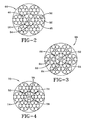
- FIGS. 2-4 Cables that meet the strength requirements for the tread belt for a tire of nominal rim diameter greater than 51 inches (130 cm) are illustrated in FIGS. 2-4.
- the cable 44 of FIG. 2 the cable 44 has a plurality of strands, with a center strand 46 surrounded and wrapped by outer sheath strands 48.
- the center strand 46 has a core 50 formed of at least three filaments 52.
- the sheath strands 48 have cores 50 formed of at least one filament 52.
- the illustrated cable 44 has the construction of 3+6+6x(1+6), excluding filament dimensions.
- the center strand 46 has a core 50 formed of at least 3 filaments 52 twisted together. If the center strand 46 has a core 50 formed of a single filament with a relatively large filament, the single filament would exhibit poor fatigue properties. The poor fatigue results from the repetitive bending stresses induced in the filament as the tire assembly travels through the tire footprint and the requirement of the tread belt 12 to maintain a circular configuration. As a result of the repetitive cycling through the footprint, the filament can break.
- the center strand core 50 from a plurality of twisted filaments such that the diameter of the twisted filament core is approximately that the same as if the core were formed from a single filament, the fatigue resistance and durability of the center strand 46, and thus the cable 44, is improved.
- twisting the filaments to form the core 50 of the center strand 46 eliminates potential migration of the twisted core 50 from the center strand 46. Should one or more of the twisted filaments break, the remaining unbroken filaments will hold the broken filament in place due to the twisted configuration of the strand core 50. Thus, migration of the broken filament(s) from the core 50 is prevented.
- forming the core 50 of the center strand 46 from multiple filaments allows each filament to be in contact with each other filament forming the core 50. By allowing each filament to be in contact with each other filament, any gapping that could form between the respective filaments is minimized.
- An additional benefit of forming the core from multiple filaments is that the shape of the core becomes dimensionally sufficient to fill the area internal of the adjacent sheath layer 54.
- a sheath layer 54 Outward of the core 50 of the center strand 46 is a sheath layer 54.
- the sheath layer 54 has at least six filaments so that the core filaments are sufficiently enclosed; the maximum number of filaments is 12.
- the filaments 52 forming the sheath layer 54 have a diameter greater than the filaments 52 forming the core 50 of the center strand 46.
- the center strand has a construction of 3x0.35+6x0.63, the filament diameters expressed in mm.
- sheath strands 48 are identical to each other.
- Each sheath strand 48 has a core 50, formed of 1 to 5 filaments.
- the filament diameter for the strand core 50 decreases as the number of filaments forming the core 50 increases.
- Outward of the core is a sheath layer 56.
- the sheath layer 56 has six filaments.
- the number of filaments 52 in the sheath layer 56 varies in the same manner as the center strand 46.
- the sheath strand construction is 1x.0.63+6x0.57.
- the diameter of the center strand 46 and the sheath strands 48 are illustrated as substantially similar.
- the selection of the filament diameters of the different strand layers enables the strands to have a substantially similar diameter.
- the diameter of the center strand 46 may also increase to be greater than the diameter of the sheath strands 48.
- the filaments forming the core of the center strand 46 should not be larger than any other filaments in the cable.
- FIGS. 3 and 4 illustrate variations of the cable of FIG 2.
- cable 58 has a center strand 60 with a core 64 formed from four filaments 52.
- the strand core 64 is formed from three filaments 52.
- the cable 70 has a center strand 72 with a core 76 formed from three filaments 52, and a sheath layer 78 of eight filaments 52.
- the sheath strands 74 the construction is the same as for the first embodiment cable 44.
- the two cables so far disclosed are known as 7x constructions wherein the cable is formed by 7 strands.
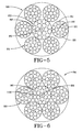
- Cables suitable for a tread belt for a tire having a nominal rim diameter greater than 57 inches (145 cm) are illustrated in FIGS. 5-8 and provide the desired increased tensile strength in comparison to the previously discussed cables.
- the cable 80 of FIG. 5 has a plurality of strands, with a center strand 82 surrounded and wrapped by outer sheath strands 84.
- Each strand 82, 84 has a core 86 formed by at least one filament 88, and at least one sheath layer 90 of filaments 88 surrounding the strand core 86.
- the illustrated strands 82, 84 have a second sheath layer 92 of filaments 88.
- the illustrated cable 80 has the construction of 3+6+12+6x(1+6+12), excluding filament dimensions.
- the center strand 82 has a core 86 formed of at least 3 filaments 88 twisted together. If the center strand 82 has a core 86 formed of a single filament with a relatively large filament, the single filament would exhibit poor fatigue properties. The poor fatigue results from the repetitive bending stresses induced in the filament as the tire assembly travels through the tire footprint and the requirement of the tread belt 12 to maintain a circular configuration. As a result of the repetitive cycling through the footprint, the filament can break.
- the center strand core 86 from a plurality of twisted filaments such that the diameter of the twisted filament core is approximately that the same as if the core were formed from a single filament, the fatigue resistance and durability of the center strand 82, and thus the cable 80, is improved.
- twisting the filaments to form the core 86 of the center strand 82 eliminates potential migration of the twisted core 86 from the center strand 82. Should one or more of the twisted filaments break, the remaining unbroken filaments will hold the broken filament in place due to the twisted configuration of the strand core 86. Thus, migration of the broken filament(s) from the core 86 is prevented.
- forming the core 86 of the center strand 82 from multiple filaments allows each filament to be in contact with each other filament forming the core 86. By allowing each filament to be in contact with each other filament, any gapping that could form between the respective filaments is minimized.
- An additional benefit of forming the core from multiple filaments is that the shape of the core becomes dimensionally sufficient to fill the area internal of the adjacent sheath layer 90.
- Outward of the core 86 of the center strand 82 is at least one sheath layer 90.
- six filaments form an intermediate sheath layer 90.
- the intermediate sheath layer 90 has at least six filaments so that the core filaments are sufficiently enclosed; the maximum number of filaments is 12.
- the filaments 88 forming the intermediate sheath layer 90 have a diameter greater than the filaments 88 forming the core 86 of the center strand 82.
- Adjacent to the sheath layer 90 is an outermost sheath layer 92; illustrated as having 12 filaments.
- the outermost sheath layer 92 has a 10 to 16 filaments, the number being sufficient to enclose the intermediate sheath layer 90, so the number may be dependent upon the number of filaments 88 in the intermediate sheath layer 90.
- the filaments 88 having a diameter similar to the diameter of the filaments in the adjacent sheath layer 90.
- the center strand has a construction of 3x0.32+6x0.58+12x0.54, the filament diameters expressed in mm.
- All of the sheath strands 84 are identical to each other.
- Each sheath strand 84 has a core 86, formed of 1 to 3 filaments. The diameter for the filaments forming the strand core 86 decreases as the number of filaments forming the core 86 increases.
- Outward of the core 86 is at least one sheath layer. Illustrated are two sheath layers 90, 92.
- the intermediate sheath layer 90 has six filaments; the outer sheath layer 92 has twelve filaments.
- the number of filaments 88 in each sheath layer 90, 92 varies in the same manner as the center strand 82.
- the sheath strand construction is 1x.0.54+6x0.48+12x0.45.
- the diameter of the center strand 82 and the sheath strands 84 are illustrated as substantially similar.
- the selection of the filament diameters of the different strand layers enables the strands to have a substantially similar diameter.
- the diameter of the center strand 82 may also increase to be greater than the diameter of the sheath strands 84.
- the filaments forming the core 86 of the center strand 82 should not be larger than any other filaments in the cable.
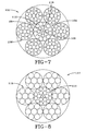
- FIGS. 6 and 7 illustrate variations of the cable of FIG 5.
- cable 94 has a center strand 96 with a core 100 formed from four filaments 88.
- the strand core 100 is formed from three filaments 88.
- the cable 102 has a center strand 104 with a core 108 formed from three filaments 88, and an intermediate sheath layer 110 of eight filaments 88, and an outermost sheath layer 112 of twelve filaments.
- the sheath strands 106 the construction is the same as for the first embodiment cable 80.
- the two cables so far disclosed are known as 7x constructions wherein the cable is formed by 7 strands.
- the cable 114 of FIG. 5 is formed with a center strand 116 and seven sheath strands 118.
- the center strand 116 has a 3+6+12 configuration.
- the sheath strands 118 have a 1+6 configuration.
- the strand core in the center strand 116 is formed of at least 3 filaments. Selection of the filament size enables the cable 114 to have a tensile strength greater than 50,000 N (5,099 kgm f ). This cable is also known as a 21+7x7.
- the steel filaments 88 used in the selected cable construction have a diameter in the range of 0.15mm to 0.50 mm.
- the steel filaments Prior to forming the cables, the steel filaments are coated for corrosion resistance and improved adhesion to the surrounding elastomer.
- the coating may be a brass or zinc coating. Both types of coating are suitable for the large tire application of the present invention.
- Zinc coating has greater heat and corrosion resistance than brass coating. Zinc coating also requires a higher curing temperature is required for the zinc coating than for the brass coating.
- the cables of the 0° ply are laid at an end count of 3 to 4 ends per inch (epi).
- the cables of the 0° ply are laid at an end count of 2 to 3 epi.
- the zero degree ply 42 has strands 44 having a construction of 3 x 0.35 + 6 x 0.63 + 6x (0.63 + 6 x 0.57), laid at an end count of 3 epi.
- the strands have a tensile strength of 28,400 N and an overall diameter of 5.3 mm.
- the inclined angled plies 36, 38 are formed of polyester strands.
- the strength ratio of the reinforcing means 44 in the zero degree ply 42 to the reinforcing strands in the inclined angle ply is 1:0.60.
- the first reinforcement layer 36 has lateral ends located axially outward of the lateral ends of the belt layers 38 and 40. As illustrated, the lateral ends of the belt layers 36, 38, and 40 are staggered. The lateral ends of the zero degree layer 42 are axially inward of the adjacent layer 36. By insuring that at least belt layer 36 overhangs or extend beyond the zero degree layer 42, the first reinforcement layer 36 provides added protection against cut damage of the cables 44. As can be easily appreciated as a large sharp rock is rolled over in the path of the tread belt, the lateral ends of the tread belt can deflect and the belt layers 36, 38, by overhanging, actually can bend over the zero degree cables 44 stopping the rock from cutting the cables 44.
- lay-up order of the belts 36, 38, 40, 42 may be modified to vary the tread belt characteristics.
- the zero-degree layer 42 may be located between the inclined belt layers 36, 38, see FIG. 9, or radially outward of the inclined belt layers 36, 38, see FIG. 10.
- the 90° layer 40 may be located radially beneath the inclined belt layers 36, 38.
- tread belts in combination with a single zero degree belt, are illustrated, it is within the scope of the invention to use other numbers of tread belt layers as needed.
- the combination of a removable tire tread belt 12 with a tire carcass 14 for use with large earthmoving vehicles is important in that it enables a portion of a tire 10 to be replaced instead of the entire tire in the event that one portion of the tire, i.e., the tire belt 12 or the tire carcass 14, wears out before the other part.
- it may be desirable to have different types of tread designs such as, for example, driving or steering tread designs. This feature allows for a less expensive means of changing the tire tread to construct the appropriate style of desired tire. This feature would greatly reduce the cost of storing spare tires and could even extend the operating time of the tires.
Landscapes
- Engineering & Computer Science (AREA)
- Mechanical Engineering (AREA)
- Tires In General (AREA)
Abstract
Description
Claims (10)
- A tread belt (12) for installing about the circumference of a tire carcass (14) after the tread belt (12) and tire carcass (14) have been separately assembled and cured, wherein
the tread belt (12) is comprised of at least a pair of belt layers (36, 38), and one layer (42) comprising reinforcing cables (44, 94, 80, 70, 102, 114) inclined at substantially zero degrees relative to the circumferential direction of the tire assembly,
the tread belt (12) being characterized by the reinforcing cables (44, 70, 80, 94, 102, 114) of the zero degree layer having a tensile strength of at least 27,500 N. - The tread belt of claim 1, wherein the at least pair of belt layers (36, 38), are comprised of reinforcing strands or cables having a tensile strength, and the tensile strength ratio between the reinforcing cables (44, 70, 80, 94, 102, 114) of the zero degree layer (42) and the reinforcing strands or cables of the at least a pair of belt layers has a range of 1:0.40 to 1:1.
- The tread belt of claim 1 or 2, wherein the reinforcing cables cables (44, 70, 80, 94, 102, 114) are comprised of filaments (52, 88), the filaments (52, 88) being brass or zinc coated.
- The tread belt of at least one of the preceding claims, wherein the layer (42) comprising the zero degree inclined cables is located either radially outward of a pair of the belt layers (36, 38), or radially outward of the belt layers (36, 38), or between a pair of the belt layers (36, 38).
- The tread belt of at least one of the preceding claims, wherein the reinforcing cables (40, 70, 80, 94, 102, 114) are comprised of a center strand (46, 96, 104, 60, 72, 82, 166) surrounded by a plurality of sheath strands (98, 48, 62, 74, 84, 106, 118), the center strand being comprised of a core (100, 50, 64, 76, 86, 108) surrounded by at least one sheath layer (90, 92, 54, 56, 78, 110, 112) of filaments (52, 88), the core of the center strand being formed of at least three filaments.
- The tread belt of claim 5, wherein the center strands has two sheath layers of filaments and/or wherein the reinforcing cables are comprised of 6 or 7 sheath strands.
- The tread belt of at least one of the preceding claims, wherein the reinforcing cables have a 7x construction, and wherein the 7x construction has a center strand, the center strand having a core formed by at least three filaments.
- The tread belt of at least one of the preceding claims, wherein the tread belt (12) is further comprised of a third layer (40) comprising inextensible reinforcing means, the reinforcing means inclined at an angle greater than 80° relative to the circumferential direction of the tire assembly.
- The tread belt of claim 8, wherein the third layer (40) is located radially outward of the at least two belt layers (36, 38).
- A two-piece tire assembly having a removable tread belt (12) for installing about the circumference of a tire carcass (14) and the tire carcass (14) having an inflated and unloaded outer circumferential surface having an axial dimension no greater than the axial width of the removable tread belt (12), wherein the tread belt (12) is a tread belt according to at least one of the previous claims.
Applications Claiming Priority (4)
| Application Number | Priority Date | Filing Date | Title |
|---|---|---|---|
| US444518 | 2003-05-23 | ||
| US10/444,527 US7104299B2 (en) | 2001-04-23 | 2003-05-23 | Two piece tire with improved tire tread belt |
| US10/444,518 US7093634B2 (en) | 2001-04-23 | 2003-05-23 | Two piece tire with improved tire tread belt |
| US444527 | 2003-05-25 |
Publications (2)
| Publication Number | Publication Date |
|---|---|
| EP1479535A2 true EP1479535A2 (en) | 2004-11-24 |
| EP1479535A3 EP1479535A3 (en) | 2006-03-15 |
Family
ID=33101148
Family Applications (1)
| Application Number | Title | Priority Date | Filing Date |
|---|---|---|---|
| EP04102127A Withdrawn EP1479535A3 (en) | 2003-05-23 | 2004-05-14 | Two piece tire with improved tire tread belt |
Country Status (4)
| Country | Link |
|---|---|
| EP (1) | EP1479535A3 (en) |
| AU (1) | AU2004202089B2 (en) |
| BR (1) | BRPI0401738A (en) |
| CA (1) | CA2466988A1 (en) |
Cited By (5)
| Publication number | Priority date | Publication date | Assignee | Title |
|---|---|---|---|---|
| EP1795371A1 (en) * | 2005-12-08 | 2007-06-13 | The Goodyear Tire & Rubber Company | High elongation cable |
| US7458200B2 (en) | 2005-12-08 | 2008-12-02 | The Goodyear Tire & Rubber Co. | High elongation cable |
| EP2298986A4 (en) * | 2008-06-13 | 2014-05-07 | Bridgestone Corp | Steel cord for reinforcement of rubber product and pneumatic tire using same |
| FR3014914A1 (en) * | 2013-12-16 | 2015-06-19 | Michelin & Cie | TWO-LAYER MULTI-TONE METAL CABLE |
| CN108136823A (en) * | 2016-07-01 | 2018-06-08 | 科德沙技术纺织品股份公司 | Novel double Elastic Carbon fiber cords as band |
Family Cites Families (6)
| Publication number | Priority date | Publication date | Assignee | Title |
|---|---|---|---|---|
| CH518192A (en) * | 1970-03-12 | 1972-01-31 | Pirelli | Tread ring for tread tire separated from the carcass |
| US4050495A (en) * | 1976-01-05 | 1977-09-27 | The Goodyear Tire & Rubber Company | Removable tread belt |
| US6099797A (en) * | 1996-09-04 | 2000-08-08 | The Goodyear Tire & Rubber Company | Steel tire cord with high tensile strength |
| DE19649507C1 (en) * | 1996-11-29 | 1998-04-23 | Continental Ag | Pneumatic vehicle tire with belt and bandage |
| US6390165B1 (en) * | 1997-05-20 | 2002-05-21 | The Goodyear Tire & Rubber Company | Tire with improved carcass ply turnup configuration |
| US6272830B1 (en) * | 2000-02-18 | 2001-08-14 | The Goodyear Tire & Rubber Company | Steel cord for reinforcing elastomeric articles |
-
2004
- 2004-05-12 BR BRPI0401738 patent/BRPI0401738A/en not_active IP Right Cessation
- 2004-05-12 CA CA 2466988 patent/CA2466988A1/en not_active Abandoned
- 2004-05-14 EP EP04102127A patent/EP1479535A3/en not_active Withdrawn
- 2004-05-17 AU AU2004202089A patent/AU2004202089B2/en not_active Ceased
Cited By (8)
| Publication number | Priority date | Publication date | Assignee | Title |
|---|---|---|---|---|
| EP1795371A1 (en) * | 2005-12-08 | 2007-06-13 | The Goodyear Tire & Rubber Company | High elongation cable |
| US7458200B2 (en) | 2005-12-08 | 2008-12-02 | The Goodyear Tire & Rubber Co. | High elongation cable |
| CN1978722B (en) * | 2005-12-08 | 2010-10-27 | 固特异轮胎和橡胶公司 | High elongation cable |
| EP2298986A4 (en) * | 2008-06-13 | 2014-05-07 | Bridgestone Corp | Steel cord for reinforcement of rubber product and pneumatic tire using same |
| US8991457B2 (en) | 2008-06-13 | 2015-03-31 | Bridgestone Corporation | Steel cord for reinforcement of rubber articles and pneumatic tire using the same |
| FR3014914A1 (en) * | 2013-12-16 | 2015-06-19 | Michelin & Cie | TWO-LAYER MULTI-TONE METAL CABLE |
| WO2015090921A1 (en) * | 2013-12-16 | 2015-06-25 | Compagnie Generale Des Etablissements Michelin | Two-layer multi-strand metal cable |
| CN108136823A (en) * | 2016-07-01 | 2018-06-08 | 科德沙技术纺织品股份公司 | Novel double Elastic Carbon fiber cords as band |
Also Published As
| Publication number | Publication date |
|---|---|
| EP1479535A3 (en) | 2006-03-15 |
| CA2466988A1 (en) | 2004-11-23 |
| AU2004202089B2 (en) | 2009-07-30 |
| AU2004202089A1 (en) | 2004-12-09 |
| BRPI0401738A (en) | 2005-01-18 |
Similar Documents
| Publication | Publication Date | Title |
|---|---|---|
| US7104299B2 (en) | Two piece tire with improved tire tread belt | |
| US7458200B2 (en) | High elongation cable | |
| US5115853A (en) | Pneumatic tire with belt overlay structure reinforced with low denier nylon cords | |
| EP3838623B1 (en) | Truck tire | |
| EP2199103B1 (en) | Reinforcement layer having cords with alternating straight and waved portions for a pneumatic tire | |
| US8117818B2 (en) | Steel cord, composite of rubber and steel cord, and tire | |
| US6561241B2 (en) | Two piece tire with improved tire tread belt and carcass | |
| US20020005239A1 (en) | Crown reinforcement for a radial tire | |
| US7093634B2 (en) | Two piece tire with improved tire tread belt | |
| EP2423001B1 (en) | Pneumatic tire | |
| EP4228906B1 (en) | Non-pneumatic tire having reinforced support structure and method of making same | |
| EP4011645B1 (en) | Truck tire | |
| US6966351B2 (en) | Tire bead configuration | |
| AU2004202089B2 (en) | Two Piece Tire with Improved Tire Tread Belt | |
| US20070131331A1 (en) | Tire assembly with high elongation cable belt | |
| EP4011646B1 (en) | Truck tire | |
| EP1795371B1 (en) | High elongation cable | |
| EP3736141B1 (en) | Radial tire | |
| US20210170795A1 (en) | Shear band | |
| CA2261397A1 (en) | Radial tires containing strands of untwisted steel filaments in a belt ply layer | |
| EP4011647B1 (en) | Truck tire | |
| CN114633584A (en) | Tire with protective belt structure |
Legal Events
| Date | Code | Title | Description |
|---|---|---|---|
| PUAI | Public reference made under article 153(3) epc to a published international application that has entered the european phase |
Free format text: ORIGINAL CODE: 0009012 |
|
| AK | Designated contracting states |
Kind code of ref document: A2 Designated state(s): AT BE BG CH CY CZ DE DK EE ES FI FR GB GR HU IE IT LI LU MC NL PL PT RO SE SI SK TR |
|
| AX | Request for extension of the european patent |
Extension state: AL HR LT LV MK |
|
| PUAL | Search report despatched |
Free format text: ORIGINAL CODE: 0009013 |
|
| AK | Designated contracting states |
Kind code of ref document: A3 Designated state(s): AT BE BG CH CY CZ DE DK EE ES FI FR GB GR HU IE IT LI LU MC NL PL PT RO SE SI SK TR |
|
| AX | Request for extension of the european patent |
Extension state: AL HR LT LV MK |
|
| 17P | Request for examination filed |
Effective date: 20060915 |
|
| AKX | Designation fees paid |
Designated state(s): DE FR GB IT |
|
| STAA | Information on the status of an ep patent application or granted ep patent |
Free format text: STATUS: THE APPLICATION HAS BEEN WITHDRAWN |
|
| 18W | Application withdrawn |
Effective date: 20110106 |