EP1479504A1 - Screw with heat exchange function, mixer and extruder - Google Patents
Screw with heat exchange function, mixer and extruder Download PDFInfo
- Publication number
- EP1479504A1 EP1479504A1 EP04011830A EP04011830A EP1479504A1 EP 1479504 A1 EP1479504 A1 EP 1479504A1 EP 04011830 A EP04011830 A EP 04011830A EP 04011830 A EP04011830 A EP 04011830A EP 1479504 A1 EP1479504 A1 EP 1479504A1
- Authority
- EP
- European Patent Office
- Prior art keywords
- heat exchange
- exchange medium
- screw
- split
- pipe
- Prior art date
- Legal status (The legal status is an assumption and is not a legal conclusion. Google has not performed a legal analysis and makes no representation as to the accuracy of the status listed.)
- Granted
Links
- 239000000463 material Substances 0.000 claims description 8
- 239000002994 raw material Substances 0.000 abstract description 13
- 238000001125 extrusion Methods 0.000 abstract description 4
- 238000005452 bending Methods 0.000 description 6
- 239000002826 coolant Substances 0.000 description 5
- 239000007788 liquid Substances 0.000 description 5
- 230000007423 decrease Effects 0.000 description 4
- 230000002093 peripheral effect Effects 0.000 description 4
- 230000000694 effects Effects 0.000 description 3
- 238000012423 maintenance Methods 0.000 description 3
- 238000003466 welding Methods 0.000 description 3
- 230000002542 deteriorative effect Effects 0.000 description 2
- 239000002184 metal Substances 0.000 description 2
- -1 vapor Substances 0.000 description 2
- 238000004891 communication Methods 0.000 description 1
- 238000001816 cooling Methods 0.000 description 1
- 235000012438 extruded product Nutrition 0.000 description 1
- 238000000034 method Methods 0.000 description 1
- 229920005989 resin Polymers 0.000 description 1
- 239000011347 resin Substances 0.000 description 1
- 229920005992 thermoplastic resin Polymers 0.000 description 1
Images



Classifications
-
- B—PERFORMING OPERATIONS; TRANSPORTING
- B29—WORKING OF PLASTICS; WORKING OF SUBSTANCES IN A PLASTIC STATE IN GENERAL
- B29B—PREPARATION OR PRETREATMENT OF THE MATERIAL TO BE SHAPED; MAKING GRANULES OR PREFORMS; RECOVERY OF PLASTICS OR OTHER CONSTITUENTS OF WASTE MATERIAL CONTAINING PLASTICS
- B29B7/00—Mixing; Kneading
- B29B7/30—Mixing; Kneading continuous, with mechanical mixing or kneading devices
- B29B7/34—Mixing; Kneading continuous, with mechanical mixing or kneading devices with movable mixing or kneading devices
- B29B7/38—Mixing; Kneading continuous, with mechanical mixing or kneading devices with movable mixing or kneading devices rotary
- B29B7/46—Mixing; Kneading continuous, with mechanical mixing or kneading devices with movable mixing or kneading devices rotary with more than one shaft
- B29B7/48—Mixing; Kneading continuous, with mechanical mixing or kneading devices with movable mixing or kneading devices rotary with more than one shaft with intermeshing devices, e.g. screws
- B29B7/482—Mixing; Kneading continuous, with mechanical mixing or kneading devices with movable mixing or kneading devices rotary with more than one shaft with intermeshing devices, e.g. screws provided with screw parts in addition to other mixing parts, e.g. paddles, gears, discs
-
- B—PERFORMING OPERATIONS; TRANSPORTING
- B29—WORKING OF PLASTICS; WORKING OF SUBSTANCES IN A PLASTIC STATE IN GENERAL
- B29B—PREPARATION OR PRETREATMENT OF THE MATERIAL TO BE SHAPED; MAKING GRANULES OR PREFORMS; RECOVERY OF PLASTICS OR OTHER CONSTITUENTS OF WASTE MATERIAL CONTAINING PLASTICS
- B29B7/00—Mixing; Kneading
- B29B7/30—Mixing; Kneading continuous, with mechanical mixing or kneading devices
- B29B7/34—Mixing; Kneading continuous, with mechanical mixing or kneading devices with movable mixing or kneading devices
- B29B7/38—Mixing; Kneading continuous, with mechanical mixing or kneading devices with movable mixing or kneading devices rotary
- B29B7/46—Mixing; Kneading continuous, with mechanical mixing or kneading devices with movable mixing or kneading devices rotary with more than one shaft
- B29B7/465—Mixing; Kneading continuous, with mechanical mixing or kneading devices with movable mixing or kneading devices rotary with more than one shaft each shaft comprising rotor parts of the Banbury type in addition to screw parts
-
- B—PERFORMING OPERATIONS; TRANSPORTING
- B29—WORKING OF PLASTICS; WORKING OF SUBSTANCES IN A PLASTIC STATE IN GENERAL
- B29B—PREPARATION OR PRETREATMENT OF THE MATERIAL TO BE SHAPED; MAKING GRANULES OR PREFORMS; RECOVERY OF PLASTICS OR OTHER CONSTITUENTS OF WASTE MATERIAL CONTAINING PLASTICS
- B29B7/00—Mixing; Kneading
- B29B7/30—Mixing; Kneading continuous, with mechanical mixing or kneading devices
- B29B7/34—Mixing; Kneading continuous, with mechanical mixing or kneading devices with movable mixing or kneading devices
- B29B7/38—Mixing; Kneading continuous, with mechanical mixing or kneading devices with movable mixing or kneading devices rotary
- B29B7/46—Mixing; Kneading continuous, with mechanical mixing or kneading devices with movable mixing or kneading devices rotary with more than one shaft
- B29B7/48—Mixing; Kneading continuous, with mechanical mixing or kneading devices with movable mixing or kneading devices rotary with more than one shaft with intermeshing devices, e.g. screws
- B29B7/488—Parts, e.g. casings, sealings; Accessories, e.g. flow controlling or throttling devices
-
- B—PERFORMING OPERATIONS; TRANSPORTING
- B29—WORKING OF PLASTICS; WORKING OF SUBSTANCES IN A PLASTIC STATE IN GENERAL
- B29B—PREPARATION OR PRETREATMENT OF THE MATERIAL TO BE SHAPED; MAKING GRANULES OR PREFORMS; RECOVERY OF PLASTICS OR OTHER CONSTITUENTS OF WASTE MATERIAL CONTAINING PLASTICS
- B29B7/00—Mixing; Kneading
- B29B7/30—Mixing; Kneading continuous, with mechanical mixing or kneading devices
- B29B7/34—Mixing; Kneading continuous, with mechanical mixing or kneading devices with movable mixing or kneading devices
- B29B7/38—Mixing; Kneading continuous, with mechanical mixing or kneading devices with movable mixing or kneading devices rotary
- B29B7/46—Mixing; Kneading continuous, with mechanical mixing or kneading devices with movable mixing or kneading devices rotary with more than one shaft
- B29B7/48—Mixing; Kneading continuous, with mechanical mixing or kneading devices with movable mixing or kneading devices rotary with more than one shaft with intermeshing devices, e.g. screws
- B29B7/488—Parts, e.g. casings, sealings; Accessories, e.g. flow controlling or throttling devices
- B29B7/489—Screws
-
- B—PERFORMING OPERATIONS; TRANSPORTING
- B29—WORKING OF PLASTICS; WORKING OF SUBSTANCES IN A PLASTIC STATE IN GENERAL
- B29B—PREPARATION OR PRETREATMENT OF THE MATERIAL TO BE SHAPED; MAKING GRANULES OR PREFORMS; RECOVERY OF PLASTICS OR OTHER CONSTITUENTS OF WASTE MATERIAL CONTAINING PLASTICS
- B29B7/00—Mixing; Kneading
- B29B7/80—Component parts, details or accessories; Auxiliary operations
- B29B7/82—Heating or cooling
-
- B—PERFORMING OPERATIONS; TRANSPORTING
- B29—WORKING OF PLASTICS; WORKING OF SUBSTANCES IN A PLASTIC STATE IN GENERAL
- B29C—SHAPING OR JOINING OF PLASTICS; SHAPING OF MATERIAL IN A PLASTIC STATE, NOT OTHERWISE PROVIDED FOR; AFTER-TREATMENT OF THE SHAPED PRODUCTS, e.g. REPAIRING
- B29C48/00—Extrusion moulding, i.e. expressing the moulding material through a die or nozzle which imparts the desired form; Apparatus therefor
- B29C48/25—Component parts, details or accessories; Auxiliary operations
- B29C48/252—Drive or actuation means; Transmission means; Screw supporting means
-
- B—PERFORMING OPERATIONS; TRANSPORTING
- B29—WORKING OF PLASTICS; WORKING OF SUBSTANCES IN A PLASTIC STATE IN GENERAL
- B29C—SHAPING OR JOINING OF PLASTICS; SHAPING OF MATERIAL IN A PLASTIC STATE, NOT OTHERWISE PROVIDED FOR; AFTER-TREATMENT OF THE SHAPED PRODUCTS, e.g. REPAIRING
- B29C48/00—Extrusion moulding, i.e. expressing the moulding material through a die or nozzle which imparts the desired form; Apparatus therefor
- B29C48/25—Component parts, details or accessories; Auxiliary operations
- B29C48/36—Means for plasticising or homogenising the moulding material or forcing it through the nozzle or die
- B29C48/395—Means for plasticising or homogenising the moulding material or forcing it through the nozzle or die using screws surrounded by a cooperating barrel, e.g. single screw extruders
- B29C48/40—Means for plasticising or homogenising the moulding material or forcing it through the nozzle or die using screws surrounded by a cooperating barrel, e.g. single screw extruders using two or more parallel screws or at least two parallel non-intermeshing screws, e.g. twin screw extruders
- B29C48/41—Intermeshing counter-rotating screws
-
- B—PERFORMING OPERATIONS; TRANSPORTING
- B29—WORKING OF PLASTICS; WORKING OF SUBSTANCES IN A PLASTIC STATE IN GENERAL
- B29C—SHAPING OR JOINING OF PLASTICS; SHAPING OF MATERIAL IN A PLASTIC STATE, NOT OTHERWISE PROVIDED FOR; AFTER-TREATMENT OF THE SHAPED PRODUCTS, e.g. REPAIRING
- B29C48/00—Extrusion moulding, i.e. expressing the moulding material through a die or nozzle which imparts the desired form; Apparatus therefor
- B29C48/25—Component parts, details or accessories; Auxiliary operations
- B29C48/36—Means for plasticising or homogenising the moulding material or forcing it through the nozzle or die
- B29C48/50—Details of extruders
- B29C48/505—Screws
- B29C48/51—Screws with internal flow passages, e.g. for molten material
- B29C48/515—Screws with internal flow passages, e.g. for molten material for auxiliary fluids, e.g. foaming agents
-
- B—PERFORMING OPERATIONS; TRANSPORTING
- B29—WORKING OF PLASTICS; WORKING OF SUBSTANCES IN A PLASTIC STATE IN GENERAL
- B29C—SHAPING OR JOINING OF PLASTICS; SHAPING OF MATERIAL IN A PLASTIC STATE, NOT OTHERWISE PROVIDED FOR; AFTER-TREATMENT OF THE SHAPED PRODUCTS, e.g. REPAIRING
- B29C48/00—Extrusion moulding, i.e. expressing the moulding material through a die or nozzle which imparts the desired form; Apparatus therefor
- B29C48/25—Component parts, details or accessories; Auxiliary operations
- B29C48/36—Means for plasticising or homogenising the moulding material or forcing it through the nozzle or die
- B29C48/50—Details of extruders
- B29C48/505—Screws
- B29C48/575—Screws provided with elements of a generally circular cross-section for shearing the melt, i.e. shear-ring elements
-
- B—PERFORMING OPERATIONS; TRANSPORTING
- B29—WORKING OF PLASTICS; WORKING OF SUBSTANCES IN A PLASTIC STATE IN GENERAL
- B29C—SHAPING OR JOINING OF PLASTICS; SHAPING OF MATERIAL IN A PLASTIC STATE, NOT OTHERWISE PROVIDED FOR; AFTER-TREATMENT OF THE SHAPED PRODUCTS, e.g. REPAIRING
- B29C48/00—Extrusion moulding, i.e. expressing the moulding material through a die or nozzle which imparts the desired form; Apparatus therefor
- B29C48/25—Component parts, details or accessories; Auxiliary operations
- B29C48/36—Means for plasticising or homogenising the moulding material or forcing it through the nozzle or die
- B29C48/50—Details of extruders
- B29C48/505—Screws
- B29C48/63—Screws having sections without mixing elements or threads, i.e. having cylinder shaped sections
-
- B—PERFORMING OPERATIONS; TRANSPORTING
- B29—WORKING OF PLASTICS; WORKING OF SUBSTANCES IN A PLASTIC STATE IN GENERAL
- B29C—SHAPING OR JOINING OF PLASTICS; SHAPING OF MATERIAL IN A PLASTIC STATE, NOT OTHERWISE PROVIDED FOR; AFTER-TREATMENT OF THE SHAPED PRODUCTS, e.g. REPAIRING
- B29C48/00—Extrusion moulding, i.e. expressing the moulding material through a die or nozzle which imparts the desired form; Apparatus therefor
- B29C48/25—Component parts, details or accessories; Auxiliary operations
- B29C48/78—Thermal treatment of the extrusion moulding material or of preformed parts or layers, e.g. by heating or cooling
- B29C48/80—Thermal treatment of the extrusion moulding material or of preformed parts or layers, e.g. by heating or cooling at the plasticising zone, e.g. by heating cylinders
- B29C48/84—Thermal treatment of the extrusion moulding material or of preformed parts or layers, e.g. by heating or cooling at the plasticising zone, e.g. by heating cylinders by heating or cooling the feeding screws
-
- B—PERFORMING OPERATIONS; TRANSPORTING
- B29—WORKING OF PLASTICS; WORKING OF SUBSTANCES IN A PLASTIC STATE IN GENERAL
- B29C—SHAPING OR JOINING OF PLASTICS; SHAPING OF MATERIAL IN A PLASTIC STATE, NOT OTHERWISE PROVIDED FOR; AFTER-TREATMENT OF THE SHAPED PRODUCTS, e.g. REPAIRING
- B29C48/00—Extrusion moulding, i.e. expressing the moulding material through a die or nozzle which imparts the desired form; Apparatus therefor
- B29C48/25—Component parts, details or accessories; Auxiliary operations
- B29C48/78—Thermal treatment of the extrusion moulding material or of preformed parts or layers, e.g. by heating or cooling
- B29C48/80—Thermal treatment of the extrusion moulding material or of preformed parts or layers, e.g. by heating or cooling at the plasticising zone, e.g. by heating cylinders
- B29C48/84—Thermal treatment of the extrusion moulding material or of preformed parts or layers, e.g. by heating or cooling at the plasticising zone, e.g. by heating cylinders by heating or cooling the feeding screws
- B29C48/85—Cooling
-
- B—PERFORMING OPERATIONS; TRANSPORTING
- B29—WORKING OF PLASTICS; WORKING OF SUBSTANCES IN A PLASTIC STATE IN GENERAL
- B29C—SHAPING OR JOINING OF PLASTICS; SHAPING OF MATERIAL IN A PLASTIC STATE, NOT OTHERWISE PROVIDED FOR; AFTER-TREATMENT OF THE SHAPED PRODUCTS, e.g. REPAIRING
- B29C48/00—Extrusion moulding, i.e. expressing the moulding material through a die or nozzle which imparts the desired form; Apparatus therefor
- B29C48/03—Extrusion moulding, i.e. expressing the moulding material through a die or nozzle which imparts the desired form; Apparatus therefor characterised by the shape of the extruded material at extrusion
-
- B—PERFORMING OPERATIONS; TRANSPORTING
- B29—WORKING OF PLASTICS; WORKING OF SUBSTANCES IN A PLASTIC STATE IN GENERAL
- B29C—SHAPING OR JOINING OF PLASTICS; SHAPING OF MATERIAL IN A PLASTIC STATE, NOT OTHERWISE PROVIDED FOR; AFTER-TREATMENT OF THE SHAPED PRODUCTS, e.g. REPAIRING
- B29C48/00—Extrusion moulding, i.e. expressing the moulding material through a die or nozzle which imparts the desired form; Apparatus therefor
- B29C48/25—Component parts, details or accessories; Auxiliary operations
- B29C48/36—Means for plasticising or homogenising the moulding material or forcing it through the nozzle or die
- B29C48/395—Means for plasticising or homogenising the moulding material or forcing it through the nozzle or die using screws surrounded by a cooperating barrel, e.g. single screw extruders
- B29C48/40—Means for plasticising or homogenising the moulding material or forcing it through the nozzle or die using screws surrounded by a cooperating barrel, e.g. single screw extruders using two or more parallel screws or at least two parallel non-intermeshing screws, e.g. twin screw extruders
Definitions
- the present invention relates to a screw, a mixer and an extruder which have a heat exchange function, and more particularly relates to a screw, a mixer and an extruder which have a heat exchange function enabling to supply a heat exchange medium without fatigue fracture of a heat exchange medium supply pipe even if the screw is bent and deformed during mixing and extrusion.
- a medium communication hole (referred to as a heat exchange medium chamber hereinafter) is provided in the screw of the mixer and the extruder, and the screw is constituted such that the temperature is controlled by supplying a heat exchange medium such as liquid coolant into the heat exchange medium chamber.
- the heat exchange medium chamber which is located at a center section in the radial direction, runs along the lengthwise direction, and has an opening on one shaft end.
- a heat exchange medium supply pipe is fit into the liquid coolant chamber through a rotary joint.
- the heat exchange medium supplied through the rotary joint flows through the heat exchange medium supply pipe, and flows out from an extreme end of the heat exchange medium supply pipe.
- the liquid coolant flowing out from the extreme end of the heat exchange medium supply pipe collides with a terminal end of the heat exchange medium chamber, and changes its direction toward a base end direction of the heat exchange medium supply pipe.
- the heat exchange medium then flows in a flow passage in a cylindrical shape formed between an outer periphery of the heat exchange medium supply pipe and an inner wall of the heat exchange medium chamber, and then flows out through the rotary joint.
- the heat exchange medium supply pipe which supplies the heat exchange medium into the heat exchange medium chamber of the screw of the mixer or the extruder.
- One type is constituted by one pipe, and the other type is constituted by connecting multiple pipes.
- Supports whose extreme end is in contact with the inner wall of the heat exchange medium chamber are provided at multiple locations in the lengthwise direction on the outer periphery of the heat exchange medium supply pipe of the former type. Namely, it is intended that the supports cause the center of the heat exchange medium supply pipe to coincide with the center in the radial direction of the heat exchange medium chamber.
- the heat exchange medium supply pipe of the latter type multiple pipes are connected by threadedly attaching the pipes to pipe joints also serving as a support.
- the pipe joints also serving as the support cause the center of the heat exchange medium supply pipe to coincide with the center in the radial direction of the heat exchange medium chamber (for example, see Japanese Patent Publication No. 2778797).
- the screw of the mixer or the extruder receives an offset load (bending force) from the raw material during the operation of the mixer or the extruder, the screw rotates while yielding.
- the highly rigid heat exchange medium supply pipe made of metal and the like is forcefully displaced repeatedly by the yield of the screw, and consequently, the heat exchange medium supply pipe may be fatigue-fractured. If the heat exchange medium supply pipe is fatigue-fractured, since cooling function (heat exchange function) provided for the screw decreases, it is impossible to adjust the temperature of the raw material being mixed or extruded, or to prevent the raw material which has melted, has being over heated, and has attached to the screw from deteriorating.
- a screw with a heat exchange function comprises a heat exchange medium chamber located at a center section in the radial direction of the screw which runs along the lengthwise direction of the screw; and a heat exchange medium supply pipe supplying a heat exchange medium which is stored in the heat exchange medium chamber, wherein the heat exchange medium supply pipe comprises split pipes and is split into two or more sections in the lengthwise direction, and pipe connecting means bendably connects the split pipes with each other.
- the screw it can be constructed such that a ring protrusion is provided on the end side of the split pipe, a groove into which the ring protrusion is fitted is provided on an inner surface of cylindrical section of the pipe connecting means, wherein the inner diameter of the cylindrical section of the pipe connecting means is set larger than the outer diameter of the split pipe, the diameter at the bottom of the groove is set larger than the outer diameter of the ring protrusion, and the width of the groove is set larger than the width of the ring protrusion, so that the split pipe can move in the lengthwise direction and the radial direction relative to the pipe connecting means by predetermined quantities.
- the pipe connecting means can also comprise a bendable bellows.
- a mixer according to the present invention comprises a barrel and the screw according to the present invention which is rotatably fit in the barrel, wherein material to be kneaded is supplied to the barrel and is kneaded by the screw.
- an extruder according to the present invention comprises a barrel and the screw according to the present invention which is rotatably fit in the barrel, wherein material to be mixed and extruded is supplied to the barrel and is mixed and extruded by the screw.
- the heat exchange medium supply pipe is constituted bendable using the pipe connecting means connecting the split pipes constituting the heat exchange medium supply pipe, and bends with the pipe connection means as start points, thereby absorbing the bend caused by the deformation of the screw, a bending stress is never generated on the split pipes constituting the heat exchange medium supply pipe. Therefore, there is no possibility of fatigue fracture of the heat exchange medium supply pipe for the screw according to the present invention.
- FIG. 1 is constitution description view of screws with a partial cross sectional view
- Fig. 2 is a cross sectional view of a vicinity of a base end (discharge opening side of a barrel) of the screw
- Fig. 3 is a view of a whole heat exchange medium supply pipe with a partial cross sectional view
- Fig. 4 is an enlarged view at a section A in Fig. 3 showing a connection constitution of split pipes
- Fig. 5 is a view made in a direction indicated by arrows B in Fig. 4.
- the screws 11 and 12 meshing with each other in a raw material feed section facing the raw materially supply opening are rotatably fit.
- a sleeve 14 is fit on one end of these screws 11 and 12.
- the sleeve 14 is supported by a bearing 15 fit in a bearing housing provided in the barrel 20.
- the other unillustrated ends of these screws 11 and 12 are connected to a driving apparatus (not shown).
- a heat exchange medium chamber 13 is formed at a center section in the radial direction, and runs along the lengthwise direction both in these screws 11 and 12.
- a heat exchange medium supply pipe 1 having a constitution including multiple highly rigid pipes described later is stored in the heat exchange medium chamber 13.
- the heat exchange medium supply pipe 1 supplies a heat exchange medium such as liquid coolant, vapor, gas, and oil to the heat exchange medium chamber 13.
- the base end of the heat exchange medium supply pipe 1 is connected to a pipe attaching member 8 provided with a return flow passage (through hole) 9 at a position displaced from the center in the radial direction.
- This attaching member 8 is fixed by fastening its flange section to a base end surface of the screws 11 and 12 with bolts.
- a joint attaching member 17 is inserted into and fit to the sleeve 14.
- the flange of the joint attaching member 17 is fastened to an end surface of the sleeve 14 using bolts.
- the pipe attaching member 8 is supplied with the heat exchange medium from a rotary joint 16 fastened to the joint attaching member 17 using bolts.
- the heat exchange medium supply pipe 1 is supplied with the heat exchange medium such as liquid coolant, vapor, gas, and oil from unillustrated heat exchange medium supply source through the rotary joint 16 and the pipe attaching member 8.
- the heat exchange medium supply pipe 1 is constituted as shown in Fig. 3 through Fig. 5. Namely, this heat exchange medium supply pipe 1 is constituted by five split pipes 2a through 2e, and four pipe connecting joints 4 serving as pipe connecting means which connect these five split pipes 2a through 2e with each other. Ring protrusions 3 are fixed to the vicinities of a one end of the first split pipe 2a on the base end side connected to the pipe attaching member 8, and the fifth split pipe 2e on the extreme end side among the split pipes 2a through 2e. Ring protrusions 3 having a rectangular cross section are fixed to the vicinities of the both ends of three of the second split pipe 2b through the fourth split pipe 2d, which are between the first split pipe 2a and the fifth split pipe 2e.
- the pipe connecting joint 4 includes a first half-split joint 4a and a second half-split joint 4b.
- the first and second half-split joints 4a, 4b include three supports 7 in a plate shape peripherally provided so as to be perpendicular to the outer peripheral surface of the first and second half-split joints 4a, 4b, and two lines of rectangular grooves in a semicircle shape on the inner peripheral surface of the first and second half-split joints 4a, 4b.
- the pipe connecting joint 4 having the two lines of the fitting grooves 5 and 5 on the inner peripheral surface, and the four supports 7 on the outer peripheral surface simultaneously is constituted by placing opening.sides of the first half-split joint 4a and the second half-split joint 4b together, and simultaneously welding to join the supports 7 whose surfaces opposing to each other are placed together.
- the first half-split joint 4a and the second half-split joint 4b are joined by welding the supports 7 in the present mode 1, there may be a constitution where the supports 7 are joined using a bolt.
- Two split pipes 2 are connected to each other using the pipe connecting joint 4 as described below.
- the ring protrusions 3 provided at the end sections of the split pipes 2 are respectively fit into the two lines of the rectangular grooves of the first half-split joint 4a.
- the rectangular grooves of the second half-split joint 4b are fit onto the ring protrusions 3 provided at the end sections of the split pipes 2, and end sections of the supports 7 whose surfaces opposing to each other are placed together are welded while the opening sides of the first and second half-split joints 4a and 4b are placed together.
- the inner diameter of a cylindrical section of the pipe connecting joint 4 is set larger than the outer diameter of the split pipe 2 by 2mm for example, the diameter at the bottom of the fitting groove 5 is set larger than the outer diameter of the ring protrusion 3 by 2mm, and the width of the fitting groove 5 is set larger than the width of the ring protrusion 3 by 2mm. Consequently, the split pipes 2 connected as described above can move in the lengthwise direction and the radial direction relative to the pipe connecting joint 4 by predetermined quantities. Namely, the split pipes 2 constituting the heat exchange medium supply pipe 1 according to the present mode 1 are connected so as to be bendable by a predetermined angle at the pipe connecting joint 4 section with the pipe connecting joint 4 as a start point.
- the inner diameter of the cylindrical section of the pipe connecting joint 4 is set larger than the outer diameter of the split pipe 2 by 2mm, and hence has a gap, as described above. Accordingly, the heat exchange medium leaks through this gap. However, these dimensions were determined after confirming that the temperature control function is not obstructed. Of course it is possible to seal the gap using a seal member having elasticity such as an O ring.
- the number of the pipe connecting joints 4 may be three or five, for example.
- the number of the pipe connecting joints is not limited. Namely, the number of the pipe connecting joints 4 can be determined in consideration of the maximum bend deformation quantity of the screw while the mixer is operating.
- a metal pipe is used for the split pipe 2 as the highly rigid pipe, a pipe made of other material may be used as long as the pipe does not present a bend and a yield.
- difference in size between the inner diameter of said cylindrical section of a pipe connecting joint and the outer diameter of a split pipe, between the diameter at the bottom of a fitting groove and the outer diameter of a ring protrusion, and between the width of the fitting groove and the width of the ring protrusion can be determined according to the number, the diameter and the length of the split pipe so as to be bendable by a predetermined angle, in consideration of the aforementioned leak of heat exchange medium.
- the heat exchange medium supplied through the rotary joint 16 flows into the heat exchange medium supply pipe 1 through the pipe attaching member 8, then flows through it, and flows out the extreme end of the heat exchange medium supply pipe 1.
- the heat exchange medium flowing out from the extreme end of the heat exchange medium supply pipe 1 collides with a terminal end of the heat exchange medium chamber 13, and changes its direction toward the base end of the heat exchange medium supply pipe 1.
- the heat exchange medium flows through a cylindrical flow passage 13a formed between the outer periphery of the heat exchange medium supply pipe 1 and the inner wall of the heat exchange medium chamber 13, flows through the return flow passage 9, and flows out from the system through the rotary joint 16.
- the heat exchange medium flowing in this way controls the temperature of the screws 11 and 12, and these screws 11 and 12 control the temperature of the raw material.
- these screws 11 and 12 rotate while they are bent by receiving an offset load (bending force) from the raw material as in the prior example.
- the heat exchange medium supply pipe 1 can freely bend with the pipe connecting joints 4 as the start points, which connect the split pipes 2a through 2e constituting the heat exchange medium supply pipe 1 with each other, the heat exchange medium supply pipe 1 can absorb the bend due to the deformation of the screw. Hence, a bending stress is never generated on the split pipes 2a through 2e constituting the heat exchange medium supply pipe 1. Therefore, there is no possibility of fatigue fracture as in the heat exchange medium supply pipe for the screw according to the prior example.
- the split pipes 2a through 2e are the highly rigid pipes, and hence do not practically bend or yield, it is possible to easily push the heat exchange medium supply pipe 1 into the heat exchange medium chamber 13 so that the extreme end of the heat exchange medium supply pipe 1 reaches a predetermined position.
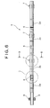
- FIG. 6 is a view of the whole heat exchange medium supply pipe with a partial cross sectional view
- Fig. 7 is an enlarged view at a section C in Fig. 6 showing a connection constitution of split pipes
- Fig. 8 is a cross sectional view made on a plane indicated by arrows D in Fig. 6.
- the heat exchange medium supply pipe 1 according to the present mode 2 is constituted by the four split pipes 2a through 2d and three bendable bellows 6 in an accordion-fold form which serve as pipe connecting means for connecting these four split pipes 2a through 2d with each other, as shown in Fig. 6 through Fig. 8.
- Four supports 7 in a plate shape are peripherally provided at 90° on an outer periphery of the second split pipe 2b through fourth split pipe 2d, except for the first split pipe 2a on the base end side connected to a pipe attaching member 8, among the split pipes 2a through 2d.
- a ring bodies 6a are fixed to both ends of the bellows 6, and the ring body 6a and an end section of the split pipe 2 are connected by welding.
- the bellows 6 is connected to the split pipe 2 through the ring body 6a in this way, since the bellows 6 is thin, and it is difficult to connect the bellows 6 itself using other methods.
- the bellows 6 may be replaced with a flexible hose (connected to the split pipe using a hose cramp), for example.
- the heat exchange medium supply pipe 1 is constituted so as to be bendable with the bellows 6 as the start points as described above, a bending stress is never generated on the first through fourth split pipes 2a through 2d constituting the heat exchange medium supply pipe 1. Hence, it is possible to stably operate the mixer for a long period, which is an effect similar to that of the above-described mode 1.
- a screw with a heat exchange function is rotatably fit in a barrel, and includes a heat exchange medium chamber located at a center section in the radial direction, running along the lengthwise direction.
- the chamber stores a heat exchange medium supply pipe supplying a heat exchange medium.
- the heat exchange medium supply pipe is constituted by split pipes split into two or more sections in the lengthwise direction. Pipe connection joints connect the split pipes with each other while securing such degrees of freedom so that these split pipes can move by predetermined quantity in the lengthwise direction and the radial direction.
- the screw enables to stably supply a heat exchange medium for a long period without fatigue fracture of a heat exchange medium supply pipe even if the screw is bent during mixing and extrusion of a raw material.
Landscapes
- Engineering & Computer Science (AREA)
- Mechanical Engineering (AREA)
- Physics & Mathematics (AREA)
- Thermal Sciences (AREA)
- Processing And Handling Of Plastics And Other Materials For Molding In General (AREA)
- Accessories For Mixers (AREA)
- Mixers Of The Rotary Stirring Type (AREA)
- Extrusion Moulding Of Plastics Or The Like (AREA)
Abstract
Description
- The present invention relates to a screw, a mixer and an extruder which have a heat exchange function, and more particularly relates to a screw, a mixer and an extruder which have a heat exchange function enabling to supply a heat exchange medium without fatigue fracture of a heat exchange medium supply pipe even if the screw is bent and deformed during mixing and extrusion.
- In a mixer or an extruder which mixes or extrudes a raw material including thermoplastic resin such as resin and a rubber material, it is important for the quality of a product to adjust the temperature of the raw material being mixed or extruded, and to prevent the raw material from being over heated, attaching to a screw, and deteriorating. Hence, a medium communication hole (referred to as a heat exchange medium chamber hereinafter) is provided in the screw of the mixer and the extruder, and the screw is constituted such that the temperature is controlled by supplying a heat exchange medium such as liquid coolant into the heat exchange medium chamber.
- In more detail, in the screw, there is formed the heat exchange medium chamber which is located at a center section in the radial direction, runs along the lengthwise direction, and has an opening on one shaft end. A heat exchange medium supply pipe is fit into the liquid coolant chamber through a rotary joint. In this case, the heat exchange medium supplied through the rotary joint flows through the heat exchange medium supply pipe, and flows out from an extreme end of the heat exchange medium supply pipe. The liquid coolant flowing out from the extreme end of the heat exchange medium supply pipe collides with a terminal end of the heat exchange medium chamber, and changes its direction toward a base end direction of the heat exchange medium supply pipe. The heat exchange medium then flows in a flow passage in a cylindrical shape formed between an outer periphery of the heat exchange medium supply pipe and an inner wall of the heat exchange medium chamber, and then flows out through the rotary joint.
- There are two types of the heat exchange medium supply pipe which supplies the heat exchange medium into the heat exchange medium chamber of the screw of the mixer or the extruder. One type is constituted by one pipe, and the other type is constituted by connecting multiple pipes. Supports whose extreme end is in contact with the inner wall of the heat exchange medium chamber are provided at multiple locations in the lengthwise direction on the outer periphery of the heat exchange medium supply pipe of the former type. Namely, it is intended that the supports cause the center of the heat exchange medium supply pipe to coincide with the center in the radial direction of the heat exchange medium chamber. As for the heat exchange medium supply pipe of the latter type, multiple pipes are connected by threadedly attaching the pipes to pipe joints also serving as a support. The pipe joints also serving as the support cause the center of the heat exchange medium supply pipe to coincide with the center in the radial direction of the heat exchange medium chamber (for example, see Japanese Patent Publication No. 2778797).
- Since the screw of the mixer or the extruder receives an offset load (bending force) from the raw material during the operation of the mixer or the extruder, the screw rotates while yielding. As a result, the highly rigid heat exchange medium supply pipe made of metal and the like is forcefully displaced repeatedly by the yield of the screw, and consequently, the heat exchange medium supply pipe may be fatigue-fractured. If the heat exchange medium supply pipe is fatigue-fractured, since cooling function (heat exchange function) provided for the screw decreases, it is impossible to adjust the temperature of the raw material being mixed or extruded, or to prevent the raw material which has melted, has being over heated, and has attached to the screw from deteriorating.
- As a result, since it is necessary to stop the operation of the mixer or the extruder for maintenance, there has been such a problem to be solved that it is not possible to expect an increase of the productivity of a mixed material or extruded products due to the decrease of the availability of the mixer or the extruder in addition to a disadvantage in terms of the running cost of the mixer or the extruder.
- Hence, it is an object of the present invention to provide a screw with a heat exchange function enabling to stably supply a heat exchange medium and to control the temperature for a long period without fatigue fracture of a heat exchange medium supply pipe even if the screw is bent during mixing and extrusion of a raw material, and to provide a mixer and an extruder comprising such a screw.
- The present invention is devised in view of the foregoing conditions, and in order to solve the above problems, a screw with a heat exchange function according to the present invention comprises a heat exchange medium chamber located at a center section in the radial direction of the screw which runs along the lengthwise direction of the screw; and a heat exchange medium supply pipe supplying a heat exchange medium which is stored in the heat exchange medium chamber, wherein the heat exchange medium supply pipe comprises split pipes and is split into two or more sections in the lengthwise direction, and pipe connecting means bendably connects the split pipes with each other.
- In the screw, it can be constructed such that a ring protrusion is provided on the end side of the split pipe, a groove into which the ring protrusion is fitted is provided on an inner surface of cylindrical section of the pipe connecting means, wherein the inner diameter of the cylindrical section of the pipe connecting means is set larger than the outer diameter of the split pipe, the diameter at the bottom of the groove is set larger than the outer diameter of the ring protrusion, and the width of the groove is set larger than the width of the ring protrusion, so that the split pipe can move in the lengthwise direction and the radial direction relative to the pipe connecting means by predetermined quantities.
- In the screw, the pipe connecting means can also comprise a bendable bellows.
- Also, a mixer according to the present invention comprises a barrel and the screw according to the present invention which is rotatably fit in the barrel, wherein material to be kneaded is supplied to the barrel and is kneaded by the screw.
- Further, an extruder according to the present invention comprises a barrel and the screw according to the present invention which is rotatably fit in the barrel, wherein material to be mixed and extruded is supplied to the barrel and is mixed and extruded by the screw.
- As described above, in the screw provided with the heat exchange function and the extruder according to the present invention, even if the screw rotates while it is bent by receiving an offset load (bending force) from a raw material, since the heat exchange medium supply pipe is constituted bendable using the pipe connecting means connecting the split pipes constituting the heat exchange medium supply pipe, and bends with the pipe connection means as start points, thereby absorbing the bend caused by the deformation of the screw, a bending stress is never generated on the split pipes constituting the heat exchange medium supply pipe. Therefore, there is no possibility of fatigue fracture of the heat exchange medium supply pipe for the screw according to the present invention.
- Hence, according to the present invention, since it is possible to stably operate a mixer or an extruder for a long period, and the frequency of the maintenance decreases, there is provided a substantial effect of an increase of the productivity due to an increase of the availability in addition to an advantage in the running cost compared with the prior example.
-
- Fig. 1 is a constitution description view of screws with a partial cross
sectional view according to a
mode 1 for carrying out the present invention. - Fig. 2 is a cross sectional view of a vicinity of a base end (discharge
opening side of a barrel) of the screw according to the
mode 1 for carrying out the present invention. - Fig. 3 is a view of a whole heat exchange medium supply pipe with a
partial cross sectional view according to the
mode 1 for carrying out the present invention. - Fig. 4 is an enlarged view at a section A in Fig. 3 showing a
connection constitution of split pipes according to the
mode 1 for carrying out the present invention. - Fig. 5 is a view made in a direction indicated by arrows B in Fig. 4
according to the
mode 1 for carrying out the present invention. - Fig. 6 is a view of a whole heat exchange medium supply pipe with a partial cross sectional view according to a mode 2 for carrying out the present invention.
- Fig. 7 is an enlarged view at a section C in Fig. 6 showing a connection constitution of split pipes according to the mode 2 for carrying out the present invention.
- Fig. 8 is a cross sectional view made on a plane indicated by arrows D in Fig. 6 according to the mode 2 of the present invention.
-
- A description will now be given of a screw with a heat exchange function according to a
mode 1 for carrying out the present invention with reference to accompanying drawings while exemplifying a case where the screw is used for a two-shaft continuous mixer (referred to as a mixer hereinafter). Fig. 1 is constitution description view of screws with a partial cross sectional view, Fig. 2 is a cross sectional view of a vicinity of a base end (discharge opening side of a barrel) of the screw, Fig. 3 is a view of a whole heat exchange medium supply pipe with a partial cross sectional view, Fig. 4 is an enlarged view at a section A in Fig. 3 showing a connection constitution of split pipes, and Fig. 5 is a view made in a direction indicated by arrows B in Fig. 4. - In the
barrel 20 of the mixer including a row material supply opening and the discharge opening spaced from each other on the both ends, thescrews sleeve 14 is fit on one end of thesescrews sleeve 14 is supported by a bearing 15 fit in a bearing housing provided in thebarrel 20. The other unillustrated ends of thesescrews exchange medium chamber 13 is formed at a center section in the radial direction, and runs along the lengthwise direction both in thesescrews medium supply pipe 1 having a constitution including multiple highly rigid pipes described later is stored in the heatexchange medium chamber 13. The heat exchangemedium supply pipe 1 supplies a heat exchange medium such as liquid coolant, vapor, gas, and oil to the heatexchange medium chamber 13. - The base end of the heat exchange
medium supply pipe 1 is connected to apipe attaching member 8 provided with a return flow passage (through hole) 9 at a position displaced from the center in the radial direction. This attachingmember 8 is fixed by fastening its flange section to a base end surface of thescrews member 17 is inserted into and fit to thesleeve 14. The flange of thejoint attaching member 17 is fastened to an end surface of thesleeve 14 using bolts. Thepipe attaching member 8 is supplied with the heat exchange medium from arotary joint 16 fastened to thejoint attaching member 17 using bolts. Namely, the heat exchangemedium supply pipe 1 is supplied with the heat exchange medium such as liquid coolant, vapor, gas, and oil from unillustrated heat exchange medium supply source through therotary joint 16 and thepipe attaching member 8. - The heat exchange
medium supply pipe 1 is constituted as shown in Fig. 3 through Fig. 5. Namely, this heat exchangemedium supply pipe 1 is constituted by fivesplit pipes 2a through 2e, and fourpipe connecting joints 4 serving as pipe connecting means which connect these fivesplit pipes 2a through 2e with each other.Ring protrusions 3 are fixed to the vicinities of a one end of thefirst split pipe 2a on the base end side connected to thepipe attaching member 8, and thefifth split pipe 2e on the extreme end side among thesplit pipes 2a through 2e.Ring protrusions 3 having a rectangular cross section are fixed to the vicinities of the both ends of three of thesecond split pipe 2b through thefourth split pipe 2d, which are between thefirst split pipe 2a and thefifth split pipe 2e. - The
pipe connecting joint 4 includes a first half-split joint 4a and a second half-split joint 4b. The first and second half-split joints supports 7 in a plate shape peripherally provided so as to be perpendicular to the outer peripheral surface of the first and second half-split joints split joints pipe connecting joint 4 having the two lines of thefitting grooves split joint 4a and the second half-split joint 4b together, and simultaneously welding to join thesupports 7 whose surfaces opposing to each other are placed together. Although the first half-split joint 4a and the second half-splitjoint 4b are joined by welding thesupports 7 in thepresent mode 1, there may be a constitution where thesupports 7 are joined using a bolt. - Two split pipes 2 are connected to each other using the pipe connecting joint 4 as described below. For example, first, the
ring protrusions 3 provided at the end sections of the split pipes 2 are respectively fit into the two lines of the rectangular grooves of the first half-split joint 4a. Then, the rectangular grooves of the second half-split joint 4b are fit onto thering protrusions 3 provided at the end sections of the split pipes 2, and end sections of thesupports 7 whose surfaces opposing to each other are placed together are welded while the opening sides of the first and second half-split joints - In this case, the inner diameter of a cylindrical section of the pipe connecting joint 4 is set larger than the outer diameter of the split pipe 2 by 2mm for example, the diameter at the bottom of the
fitting groove 5 is set larger than the outer diameter of thering protrusion 3 by 2mm, and the width of thefitting groove 5 is set larger than the width of thering protrusion 3 by 2mm. Consequently, the split pipes 2 connected as described above can move in the lengthwise direction and the radial direction relative to the pipe connecting joint 4 by predetermined quantities. Namely, the split pipes 2 constituting the heat exchangemedium supply pipe 1 according to thepresent mode 1 are connected so as to be bendable by a predetermined angle at the pipe connecting joint 4 section with the pipe connecting joint 4 as a start point. - In the
present mode 1, the inner diameter of the cylindrical section of the pipe connecting joint 4 is set larger than the outer diameter of the split pipe 2 by 2mm, and hence has a gap, as described above. Accordingly, the heat exchange medium leaks through this gap. However, these dimensions were determined after confirming that the temperature control function is not obstructed. Of course it is possible to seal the gap using a seal member having elasticity such as an O ring. In addition, although the fourpipe connecting joints 4 are used in thepresent mode 1, the number of thepipe connecting joints 4 may be three or five, for example. The number of the pipe connecting joints is not limited. Namely, the number of thepipe connecting joints 4 can be determined in consideration of the maximum bend deformation quantity of the screw while the mixer is operating. Also, although a metal pipe is used for the split pipe 2 as the highly rigid pipe, a pipe made of other material may be used as long as the pipe does not present a bend and a yield. - When a type of pipe connecting means as shown in
above mode 1 is applied, difference in size between the inner diameter of said cylindrical section of a pipe connecting joint and the outer diameter of a split pipe, between the diameter at the bottom of a fitting groove and the outer diameter of a ring protrusion, and between the width of the fitting groove and the width of the ring protrusion can be determined according to the number, the diameter and the length of the split pipe so as to be bendable by a predetermined angle, in consideration of the aforementioned leak of heat exchange medium. - A description will now be given of an operation form of the
screws mode 1. During the operation of the mixer, the heat exchange medium supplied through the rotary joint 16 flows into the heat exchangemedium supply pipe 1 through thepipe attaching member 8, then flows through it, and flows out the extreme end of the heat exchangemedium supply pipe 1. The heat exchange medium flowing out from the extreme end of the heat exchangemedium supply pipe 1 collides with a terminal end of the heatexchange medium chamber 13, and changes its direction toward the base end of the heat exchangemedium supply pipe 1. Then, the heat exchange medium flows through acylindrical flow passage 13a formed between the outer periphery of the heat exchangemedium supply pipe 1 and the inner wall of the heatexchange medium chamber 13, flows through thereturn flow passage 9, and flows out from the system through the rotary joint 16. The heat exchange medium flowing in this way controls the temperature of thescrews screws - During the above-described operation of the mixer, these
screws present mode 1, as described above, since the heat exchangemedium supply pipe 1 can freely bend with thepipe connecting joints 4 as the start points, which connect thesplit pipes 2a through 2e constituting the heat exchangemedium supply pipe 1 with each other, the heat exchangemedium supply pipe 1 can absorb the bend due to the deformation of the screw. Hence, a bending stress is never generated on thesplit pipes 2a through 2e constituting the heat exchangemedium supply pipe 1. Therefore, there is no possibility of fatigue fracture as in the heat exchange medium supply pipe for the screw according to the prior example. - As a result, according to the
present mode 1, since it is possible to stably operate the mixer for a long period, and the frequency of the maintenance decreases, there is provided a substantial effect of an increase of the productivity due to the increase of the availability in addition to an advantage in the running cost compared with the prior example. Since thesplit pipes 2a through 2e are the highly rigid pipes, and hence do not practically bend or yield, it is possible to easily push the heat exchangemedium supply pipe 1 into the heatexchange medium chamber 13 so that the extreme end of the heat exchangemedium supply pipe 1 reaches a predetermined position. - A description will now be given of a screw with a heat exchange function according to a mode 2 for carrying out the present invention with reference to accompanying drawings exemplifying a case where the screw is used for a mixer. It should be noted that since the constitution of the screw itself is similar to that of the above-described
mode 1, and only the constitution of the heat exchange medium supply pipe is different, a description would be given only of the heat exchange medium supply pipe. Fig. 6 is a view of the whole heat exchange medium supply pipe with a partial cross sectional view, Fig. 7 is an enlarged view at a section C in Fig. 6 showing a connection constitution of split pipes, and Fig. 8 is a cross sectional view made on a plane indicated by arrows D in Fig. 6. - Namely, the heat exchange
medium supply pipe 1 according to the present mode 2 is constituted by the foursplit pipes 2a through 2d and threebendable bellows 6 in an accordion-fold form which serve as pipe connecting means for connecting these foursplit pipes 2a through 2d with each other, as shown in Fig. 6 through Fig. 8. Foursupports 7 in a plate shape are peripherally provided at 90° on an outer periphery of thesecond split pipe 2b throughfourth split pipe 2d, except for thefirst split pipe 2a on the base end side connected to apipe attaching member 8, among thesplit pipes 2a through 2d. - In the present mode 2, as shown in Fig. 7, a
ring bodies 6a are fixed to both ends of thebellows 6, and thering body 6a and an end section of the split pipe 2 are connected by welding. Thebellows 6 is connected to the split pipe 2 through thering body 6a in this way, since thebellows 6 is thin, and it is difficult to connect thebellows 6 itself using other methods. Though thebellows 6 is used in the present mode 2, thebellows 6 may be replaced with a flexible hose (connected to the split pipe using a hose cramp), for example. - In the present mode 2, since the heat exchange
medium supply pipe 1 is constituted so as to be bendable with thebellows 6 as the start points as described above, a bending stress is never generated on the first throughfourth split pipes 2a through 2d constituting the heat exchangemedium supply pipe 1. Hence, it is possible to stably operate the mixer for a long period, which is an effect similar to that of the above-describedmode 1. - The above description is given of cases where the
screws medium supply pipe 1 according to the present modes are supported in a straddle mount manner in the continuous mixers. However, since technical idea of the present invention can be applied to a continuous mixer having a screw supported in a overhang mount manner, or a screw of an extruder, the technical idea is not limited to the application to the screw supported in the straddle mount manner used for the mixer. - A screw with a heat exchange function is rotatably fit in a barrel, and includes a heat exchange medium chamber located at a center section in the radial direction, running along the lengthwise direction. The chamber stores a heat exchange medium supply pipe supplying a heat exchange medium. The heat exchange medium supply pipe is constituted by split pipes split into two or more sections in the lengthwise direction. Pipe connection joints connect the split pipes with each other while securing such degrees of freedom so that these split pipes can move by predetermined quantity in the lengthwise direction and the radial direction. The screw enables to stably supply a heat exchange medium for a long period without fatigue fracture of a heat exchange medium supply pipe even if the screw is bent during mixing and extrusion of a raw material.
Claims (5)
- A screw with a heat exchange function comprising:wherein said heat exchange medium supply pipe comprises split pipes and is split into two or more sections in the lengthwise direction, and pipe connecting means bendably connects said split pipes with each other.a heat exchange medium chamber located at a center section in the radial direction of said screw, said heat exchange medium chamber running along the lengthwise direction of said screw; anda heat exchange medium supply pipe supplying a heat exchange medium, said heat exchange medium supply pipe being stored in said heat exchange medium chamber,
- The screw according to claim 1, wherein a ring protrusion is provided on the end side of said split pipe, a groove into which said ring protrusion is fitted is provided on an inner surface of cylindrical section of said pipe connecting means,
and wherein the inner diameter of said cylindrical section of said pipe connecting means is set larger than the outer diameter of said split pipe, the diameter at the bottom of said groove is set larger than the outer diameter of said ring protrusion, and the width of said groove is set larger than the width of said ring protrusion, so that said split pipe can move in the lengthwise direction and the radial direction relative to the pipe connecting means by predetermined quantities. - The screw according to claim 1, wherein said pipe connecting means comprises a bendable bellows.
- A mixer comprising:wherein material to be kneaded is supplied to said barrel and is kneaded by said screw.a barrel; andthe screw according to claim 1, said screw being rotatably fit in said barrel,
- An extruder comprising:wherein material to be mixed and extruded is supplied to said barrel and is mixed and extruded by said screw.a barrel; andthe screw according to claim 1, said screw being rotatably fit in said barrel,
Applications Claiming Priority (2)
| Application Number | Priority Date | Filing Date | Title |
|---|---|---|---|
| JP2003140600 | 2003-05-19 | ||
| JP2003140600A JP4102706B2 (en) | 2003-05-19 | 2003-05-19 | Screw, kneader and extruder with heat exchange function |
Publications (2)
| Publication Number | Publication Date |
|---|---|
| EP1479504A1 true EP1479504A1 (en) | 2004-11-24 |
| EP1479504B1 EP1479504B1 (en) | 2006-07-19 |
Family
ID=33095384
Family Applications (1)
| Application Number | Title | Priority Date | Filing Date |
|---|---|---|---|
| EP04011830A Expired - Lifetime EP1479504B1 (en) | 2003-05-19 | 2004-05-18 | Screw with heat exchange function, mixer and extruder |
Country Status (4)
| Country | Link |
|---|---|
| US (1) | US7097345B2 (en) |
| EP (1) | EP1479504B1 (en) |
| JP (1) | JP4102706B2 (en) |
| DE (1) | DE602004001541T2 (en) |
Cited By (1)
| Publication number | Priority date | Publication date | Assignee | Title |
|---|---|---|---|---|
| US12414579B2 (en) | 2017-02-15 | 2025-09-16 | Wenger Manufacturing Inc. | Food processing system including extruder with hollow core screw assembly |
Families Citing this family (13)
| Publication number | Priority date | Publication date | Assignee | Title |
|---|---|---|---|---|
| WO2007006327A1 (en) * | 2005-07-12 | 2007-01-18 | Borealis Technology Oy | Counter-rotating twin screw extruder |
| US20100127419A1 (en) * | 2008-11-24 | 2010-05-27 | Christopher John Malarkey | Ceramic honeycomb extrusion method and apparatus |
| US8507699B2 (en) | 2010-12-10 | 2013-08-13 | Sabic Innovative Plastics Ip B.V. | Bisphenol polymer structural units and method of making the same |
| US8372943B2 (en) | 2010-12-10 | 2013-02-12 | Sabic Innovative Plastics Ip B.V. | Isosorbide—containing polycarbonates and their preparation |
| EP2801660B1 (en) * | 2013-05-10 | 2015-09-16 | Starlinger & Co. Gesellschaft m.b.H. | Drive and system comprising at least one driven roller or extruder screw |
| WO2015034889A2 (en) | 2013-09-04 | 2015-03-12 | Zzyzx Polymers LLC | Methods for increasing throughput rates of solid-state extrusion devices |
| JP2015051400A (en) * | 2013-09-09 | 2015-03-19 | 株式会社栗本鐵工所 | Double arm kneader |
| WO2015073366A1 (en) * | 2013-11-12 | 2015-05-21 | Zzyzx Polymers LLC | Systems and methods of regulating temperature of a solid-state shear pulverization or solid-state melt extrusion device |
| US10028516B2 (en) | 2015-07-17 | 2018-07-24 | Wenger Manufacturing, Inc. | Apparatus and method for processing of high meat content food or feed products |
| US20190075822A1 (en) | 2017-09-08 | 2019-03-14 | Wenger Manufacturing Inc. | Method and apparatus for production of high meat content pet foods |
| JP7372741B2 (en) * | 2018-03-27 | 2023-11-01 | パナソニックホールディングス株式会社 | Manufacturing device and method for composite resin composition |
| CN111391274B (en) | 2020-03-25 | 2022-04-05 | 五邑大学 | A kind of anisotropic differential rotating extrusion device, extruder and material production method |
| JP7571485B2 (en) * | 2020-11-12 | 2024-10-23 | 株式会社ジェイテクト | Anomaly prediction system, anomaly prediction device, anomaly prediction method, and program |
Citations (5)
| Publication number | Priority date | Publication date | Assignee | Title |
|---|---|---|---|---|
| US2688770A (en) * | 1951-05-04 | 1954-09-14 | Western Electric Co | Method of and apparatus for controlling the temperature of plastic material |
| JPS56144140A (en) * | 1980-04-10 | 1981-11-10 | Oki Densen Kk | Screw for extruding plastics |
| US4355905A (en) * | 1980-03-24 | 1982-10-26 | The Dow Chemical Company | Adjustable plug seal mechanism for heat transfer zone separation in hollow screws for extrusion machines |
| JPS59160522A (en) * | 1983-03-03 | 1984-09-11 | Kobe Steel Ltd | Kneading vane of twin shaft continuous kneading machine |
| US5273356A (en) * | 1991-06-07 | 1993-12-28 | Farrel Corporation | Rotor zone cooling method and apparatus for rotors in continuous mixers of plastic materials |
Family Cites Families (5)
| Publication number | Priority date | Publication date | Assignee | Title |
|---|---|---|---|---|
| US158246A (en) * | 1874-12-29 | Signob oe one-half to john b | ||
| US2321185A (en) * | 1940-11-20 | 1943-06-08 | Joseph D Christian | Heat exchange screw conveyer |
| US2883163A (en) * | 1955-12-02 | 1959-04-21 | Stord As | Rotatable heating members for heat exchangers |
| JP2778797B2 (en) | 1990-04-05 | 1998-07-23 | 株式会社神戸製鋼所 | Screw for plastic molding machine |
| DE4412536A1 (en) * | 1994-04-12 | 1995-10-19 | Kloeckner Humboldt Deutz Ag | Preheating screw for simultaneous mixing and heating of granular or pasty material |
-
2003
- 2003-05-19 JP JP2003140600A patent/JP4102706B2/en not_active Expired - Lifetime
-
2004
- 2004-04-05 US US10/816,807 patent/US7097345B2/en not_active Expired - Lifetime
- 2004-05-18 DE DE602004001541T patent/DE602004001541T2/en not_active Expired - Lifetime
- 2004-05-18 EP EP04011830A patent/EP1479504B1/en not_active Expired - Lifetime
Patent Citations (5)
| Publication number | Priority date | Publication date | Assignee | Title |
|---|---|---|---|---|
| US2688770A (en) * | 1951-05-04 | 1954-09-14 | Western Electric Co | Method of and apparatus for controlling the temperature of plastic material |
| US4355905A (en) * | 1980-03-24 | 1982-10-26 | The Dow Chemical Company | Adjustable plug seal mechanism for heat transfer zone separation in hollow screws for extrusion machines |
| JPS56144140A (en) * | 1980-04-10 | 1981-11-10 | Oki Densen Kk | Screw for extruding plastics |
| JPS59160522A (en) * | 1983-03-03 | 1984-09-11 | Kobe Steel Ltd | Kneading vane of twin shaft continuous kneading machine |
| US5273356A (en) * | 1991-06-07 | 1993-12-28 | Farrel Corporation | Rotor zone cooling method and apparatus for rotors in continuous mixers of plastic materials |
Non-Patent Citations (2)
| Title |
|---|
| PATENT ABSTRACTS OF JAPAN vol. 006, no. 026 (M - 112) 16 February 1982 (1982-02-16) * |
| PATENT ABSTRACTS OF JAPAN vol. 009, no. 005 (C - 260) 10 January 1985 (1985-01-10) * |
Cited By (1)
| Publication number | Priority date | Publication date | Assignee | Title |
|---|---|---|---|---|
| US12414579B2 (en) | 2017-02-15 | 2025-09-16 | Wenger Manufacturing Inc. | Food processing system including extruder with hollow core screw assembly |
Also Published As
| Publication number | Publication date |
|---|---|
| JP2004338343A (en) | 2004-12-02 |
| DE602004001541T2 (en) | 2007-06-28 |
| DE602004001541D1 (en) | 2006-08-31 |
| US7097345B2 (en) | 2006-08-29 |
| EP1479504B1 (en) | 2006-07-19 |
| JP4102706B2 (en) | 2008-06-18 |
| US20040234641A1 (en) | 2004-11-25 |
Similar Documents
| Publication | Publication Date | Title |
|---|---|---|
| US7097345B2 (en) | Screw with heat exchange function, mixer and extruder | |
| US6290237B1 (en) | Flat ring packing | |
| US8113814B2 (en) | Barrel clamping system for quick assembling and dismantling of extruder barrel sections | |
| CN101186102B (en) | Material processing plant | |
| CN103363236A (en) | Pipe connector with compensator | |
| CN101779071A (en) | Hose assembly with anti-rotational coupling and crimping section | |
| EP2668461B1 (en) | Re-corable coaxial hose system | |
| CN1285898A (en) | Piston pump for high-pressure cleaning device | |
| CN107461394B (en) | Temperature Controlled Spindle Assembly with Fluid Inlet Hose | |
| KR20150142752A (en) | Jig for preventing thermal deformation | |
| US11090748B2 (en) | Device adapted to dosing pasty substances | |
| US20020076461A1 (en) | Coextrusion nozzle arrangement | |
| CN102689577A (en) | Air-conditioning apparatus for vehicle | |
| US9091379B2 (en) | Internal connector tube for use with connecting sleeve to provide airtight connection between hollow tubes | |
| US20250383037A1 (en) | Housing assembly for use in a heat exchange system | |
| KR20000018202A (en) | A fittings for tube to provide with liquid or compressed air | |
| JPH11182523A (en) | Fastening bolt | |
| US6398265B1 (en) | Fluids conduction integrated system | |
| CN114603568A (en) | Robot arm device and coating robot | |
| US6843740B2 (en) | Pressure feed to a shaft | |
| KR102165596B1 (en) | Air nozzle assembly and sealer application device including the same | |
| JPS6327190Y2 (en) | ||
| CN108626457B (en) | Reversing valve and preparation method thereof | |
| EP2713086B1 (en) | Rotating coupling | |
| JP7815459B2 (en) | Assembly for alignment |
Legal Events
| Date | Code | Title | Description |
|---|---|---|---|
| PUAI | Public reference made under article 153(3) epc to a published international application that has entered the european phase |
Free format text: ORIGINAL CODE: 0009012 |
|
| 17P | Request for examination filed |
Effective date: 20040518 |
|
| AK | Designated contracting states |
Kind code of ref document: A1 Designated state(s): AT BE BG CH CY CZ DE DK EE ES FI FR GB GR HU IE IT LI LU MC NL PL PT RO SE SI SK TR |
|
| AX | Request for extension of the european patent |
Extension state: AL HR LT LV MK |
|
| 17Q | First examination report despatched |
Effective date: 20041223 |
|
| AKX | Designation fees paid |
Designated state(s): DE FR GB IT |
|
| GRAP | Despatch of communication of intention to grant a patent |
Free format text: ORIGINAL CODE: EPIDOSNIGR1 |
|
| GRAS | Grant fee paid |
Free format text: ORIGINAL CODE: EPIDOSNIGR3 |
|
| GRAA | (expected) grant |
Free format text: ORIGINAL CODE: 0009210 |
|
| AK | Designated contracting states |
Kind code of ref document: B1 Designated state(s): DE FR GB IT |
|
| PG25 | Lapsed in a contracting state [announced via postgrant information from national office to epo] |
Ref country code: IT Free format text: LAPSE BECAUSE OF FAILURE TO SUBMIT A TRANSLATION OF THE DESCRIPTION OR TO PAY THE FEE WITHIN THE PRESCRIBED TIME-LIMIT;WARNING: LAPSES OF ITALIAN PATENTS WITH EFFECTIVE DATE BEFORE 2007 MAY HAVE OCCURRED AT ANY TIME BEFORE 2007. THE CORRECT EFFECTIVE DATE MAY BE DIFFERENT FROM THE ONE RECORDED. Effective date: 20060719 |
|
| REG | Reference to a national code |
Ref country code: GB Ref legal event code: FG4D |
|
| REF | Corresponds to: |
Ref document number: 602004001541 Country of ref document: DE Date of ref document: 20060831 Kind code of ref document: P |
|
| ET | Fr: translation filed | ||
| PLBE | No opposition filed within time limit |
Free format text: ORIGINAL CODE: 0009261 |
|
| STAA | Information on the status of an ep patent application or granted ep patent |
Free format text: STATUS: NO OPPOSITION FILED WITHIN TIME LIMIT |
|
| 26N | No opposition filed |
Effective date: 20070420 |
|
| PGRI | Patent reinstated in contracting state [announced from national office to epo] |
Ref country code: IT Effective date: 20080601 |
|
| REG | Reference to a national code |
Ref country code: FR Ref legal event code: PLFP Year of fee payment: 13 |
|
| REG | Reference to a national code |
Ref country code: FR Ref legal event code: PLFP Year of fee payment: 14 |
|
| REG | Reference to a national code |
Ref country code: FR Ref legal event code: PLFP Year of fee payment: 15 |
|
| REG | Reference to a national code |
Ref country code: DE Ref legal event code: R079 Ref document number: 602004001541 Country of ref document: DE Free format text: PREVIOUS MAIN CLASS: B29C0047840000 Ipc: B29C0048800000 |
|
| PGFP | Annual fee paid to national office [announced via postgrant information from national office to epo] |
Ref country code: FR Payment date: 20230309 Year of fee payment: 20 |
|
| PGFP | Annual fee paid to national office [announced via postgrant information from national office to epo] |
Ref country code: GB Payment date: 20230330 Year of fee payment: 20 |
|
| P01 | Opt-out of the competence of the unified patent court (upc) registered |
Effective date: 20230523 |
|
| PGFP | Annual fee paid to national office [announced via postgrant information from national office to epo] |
Ref country code: IT Payment date: 20230412 Year of fee payment: 20 Ref country code: DE Payment date: 20230321 Year of fee payment: 20 |
|
| REG | Reference to a national code |
Ref country code: DE Ref legal event code: R071 Ref document number: 602004001541 Country of ref document: DE |
|
| REG | Reference to a national code |
Ref country code: GB Ref legal event code: PE20 Expiry date: 20240517 |
|
| PG25 | Lapsed in a contracting state [announced via postgrant information from national office to epo] |
Ref country code: GB Free format text: LAPSE BECAUSE OF EXPIRATION OF PROTECTION Effective date: 20240517 |
|
| PG25 | Lapsed in a contracting state [announced via postgrant information from national office to epo] |
Ref country code: GB Free format text: LAPSE BECAUSE OF EXPIRATION OF PROTECTION Effective date: 20240517 |