EP1479497B1 - Transmission reducer with application in concrete mixers - Google Patents
Transmission reducer with application in concrete mixers Download PDFInfo
- Publication number
- EP1479497B1 EP1479497B1 EP04398004A EP04398004A EP1479497B1 EP 1479497 B1 EP1479497 B1 EP 1479497B1 EP 04398004 A EP04398004 A EP 04398004A EP 04398004 A EP04398004 A EP 04398004A EP 1479497 B1 EP1479497 B1 EP 1479497B1
- Authority
- EP
- European Patent Office
- Prior art keywords
- bucket
- pulley
- reducer
- diameter
- small
- Prior art date
- Legal status (The legal status is an assumption and is not a legal conclusion. Google has not performed a legal analysis and makes no representation as to the accuracy of the status listed.)
- Expired - Lifetime
Links
- 239000003638 chemical reducing agent Substances 0.000 title claims abstract description 25
- 230000005540 biological transmission Effects 0.000 title claims abstract description 14
- 230000033001 locomotion Effects 0.000 abstract description 5
- 238000012423 maintenance Methods 0.000 description 3
- 239000004570 mortar (masonry) Substances 0.000 description 3
- 230000002093 peripheral effect Effects 0.000 description 3
- 230000004308 accommodation Effects 0.000 description 2
- 239000004568 cement Substances 0.000 description 2
- 238000010276 construction Methods 0.000 description 2
- 229910001018 Cast iron Inorganic materials 0.000 description 1
- 229910001208 Crucible steel Inorganic materials 0.000 description 1
- 229910000831 Steel Inorganic materials 0.000 description 1
- 230000002153 concerted effect Effects 0.000 description 1
- 230000007613 environmental effect Effects 0.000 description 1
- 238000009434 installation Methods 0.000 description 1
- 238000005461 lubrication Methods 0.000 description 1
- 230000007257 malfunction Effects 0.000 description 1
- 238000004519 manufacturing process Methods 0.000 description 1
- 239000000463 material Substances 0.000 description 1
- 230000010355 oscillation Effects 0.000 description 1
- 238000013021 overheating Methods 0.000 description 1
- 239000011505 plaster Substances 0.000 description 1
- 230000002265 prevention Effects 0.000 description 1
- 230000002787 reinforcement Effects 0.000 description 1
- 239000010959 steel Substances 0.000 description 1
Images


Classifications
-
- F—MECHANICAL ENGINEERING; LIGHTING; HEATING; WEAPONS; BLASTING
- F16—ENGINEERING ELEMENTS AND UNITS; GENERAL MEASURES FOR PRODUCING AND MAINTAINING EFFECTIVE FUNCTIONING OF MACHINES OR INSTALLATIONS; THERMAL INSULATION IN GENERAL
- F16H—GEARING
- F16H37/00—Combinations of mechanical gearings, not provided for in groups F16H1/00 - F16H35/00
- F16H37/02—Combinations of mechanical gearings, not provided for in groups F16H1/00 - F16H35/00 comprising essentially only toothed or friction gearings
- F16H37/021—Combinations of mechanical gearings, not provided for in groups F16H1/00 - F16H35/00 comprising essentially only toothed or friction gearings toothed gearing combined with continuous variable friction gearing
-
- B—PERFORMING OPERATIONS; TRANSPORTING
- B28—WORKING CEMENT, CLAY, OR STONE
- B28C—PREPARING CLAY; PRODUCING MIXTURES CONTAINING CLAY OR CEMENTITIOUS MATERIAL, e.g. PLASTER
- B28C5/00—Apparatus or methods for producing mixtures of cement with other substances, e.g. slurries, mortars, porous or fibrous compositions
- B28C5/08—Apparatus or methods for producing mixtures of cement with other substances, e.g. slurries, mortars, porous or fibrous compositions using driven mechanical means affecting the mixing
- B28C5/0806—Details; Accessories
- B28C5/0831—Drives or drive systems, e.g. toothed racks, winches
- B28C5/0837—Drives for mixers of the tilted-drum type
-
- F—MECHANICAL ENGINEERING; LIGHTING; HEATING; WEAPONS; BLASTING
- F16—ENGINEERING ELEMENTS AND UNITS; GENERAL MEASURES FOR PRODUCING AND MAINTAINING EFFECTIVE FUNCTIONING OF MACHINES OR INSTALLATIONS; THERMAL INSULATION IN GENERAL
- F16H—GEARING
- F16H7/00—Gearings for conveying rotary motion by endless flexible members
- F16H7/02—Gearings for conveying rotary motion by endless flexible members with belts; with V-belts
-
- F—MECHANICAL ENGINEERING; LIGHTING; HEATING; WEAPONS; BLASTING
- F16—ENGINEERING ELEMENTS AND UNITS; GENERAL MEASURES FOR PRODUCING AND MAINTAINING EFFECTIVE FUNCTIONING OF MACHINES OR INSTALLATIONS; THERMAL INSULATION IN GENERAL
- F16H—GEARING
- F16H7/00—Gearings for conveying rotary motion by endless flexible members
- F16H7/06—Gearings for conveying rotary motion by endless flexible members with chains
Definitions
- This invention concerns a transmission reducer to be used as a reducer of peripheral speed, in concrete or mortar mixers in the building industry.
- the concrete mixers that are used nowadays generally have a motor which occupies a box that is too large, the motor has to have average/high power and, simultaneously, low rotation.
- the motion power is applied by direct drive, accomplished by an endless screw or a gear wheel, which, in turn, gears in a circular rack that involves the mixing bucket.
- the concrete mixers are of common use and an indispensable tool in accommodation, maintenance works or even in the construction of urban buildings. In any work that requires the use of mortar the concrete mixer is mandatory.
- DE 1 45 92 91 discloses a concrete mixer with all the features of the preamble of independent claim 1, comprising a bucket and a motor, which are directly and solidly mounted on a wheelbarrow-like frame and connected by means of a three-stage transmission reducer, wherein the motor is arranged in the back of the bucket laterally to the bucket rotation shaft.
- US 4,043,540 discloses a paddle assembly for a plaster or mortar mixer of the type having a pivotal drum and a rotatable paddle shaft in which the reduction stage, comprises a large drive gear which is in meshing engagement with a small pinion gear thereby driving the paddle shaft.
- US 4,097,925 discloses a conventional cement mixer container rotatably supported on the truck frame and driven by a power gear train comprising a large driven gear driven by a gear chain in turn driven by an intermediate driven gear driven by a primary drive chain, in turn driven by a primary drive gear.
- This transmission reducer is the result of the practical and technical knowledge of the inventor, of long studies which include the direct production of some components, assembly and separate and concerted officinal trials of the parts used to test the mechanical system, applying the reducer in a concrete mixer, picture 3, especially developed and constructed to be used in this reducer, where you can see the box (20) inside the structure of the base of the crankshaft where the reducer of this invention is set up, the access lid (24) for the installation and maintenance of the reducer, the box to keep the motor in a vertical position (21), the carrying chip at the basis of the bucket in heavy-duty steel and the centre of the crankshaft with bearings (22) which receives the shaft (8 pic. 1) of the reducer and the groove of the bilge of the bucket (23) without the traditional rack.
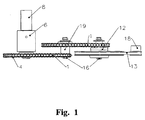
- the reducer that is now presented is made up of a set of interconnected mechanical pieces, positioned according to picture 1, and includes a small pulley (18 pic. 1 and pic. 2) with just one groove for the trapezoidal chain, a mixed pulley (12 pic. 1 e pic. 2) made up of a large diameter wheel with a trapezoidal groove (12a pic. 2) fixed in the same axis to a small diameter gear wheel (12b pic. 2), a double rack (19 pic. 1 and pic. 2) that has two gear wheels fixed together, parallel and in the same axis, one of the wheels has a big diameter (19a pic. 2) and the other has a small one (19b pic. 2) and a simple large diameter rack (4 pic. 1 and pic. 2) that is fixed to the same axis (8 pic. 1 and pic. 2) that, as it is being set up in the centre of the crankshaft, with the support of bearings and the bushing (6 pic. 2) is secured at the basis of the concrete mixer's bucket (22 pic. 3).
- the first pulley (18 pic. 1 and pic. 2) has a reference diameter almost equal to the diameter of the shaft of the motor used, and has a reference diameter similar to the one of the small gear wheels (12b e 19b pic. 2).
- the second pulley (12a pic 2) and the gear wheels (19a pic. 2) and (4 pic. 1 and pic. 2) have a similar reference diameter that is approximately four times bigger than the reference diameter of the driving pulley (18 pic. 1 and pic. 2).
- the axis (8) which is incorporated in the basis of the concrete mixer's bucket, is fixed, while the axis (16) of the pulleys (12 and 19 pic.1 and pic. 2), just as the motor's tightening screws, are used in torn holes and equipped with locking anti-releasing.
- the pulleys (18) and (12) may be replaced by others, with the same size, but with a double, or, if necessary, even triple, trapezoidal groove to allow the use of two or three trapezoidal chains, according to the case and the model of the concrete mixer.
- the use of the trapezoidal belt (13) is suitable for the dampening of the start of the motor and the resistance of the bucket's inertial force if it is loaded.
- This reducer can be set up in an autonomous box, so that it can be applied to any driving force, or set up directly in the bar that serves as a basis for the crankshaft of the concrete mixer according to (20 pic. 3).
- This invention besides being a more economical mechanical solution, which can be used in concrete mixers of several sizes, also allows the use of motorizations of a lesser energetic consumption, and it occupies a reduced but suitable space in the machine (20 pic. 3), this space is in the interior of the bars that structure the end of the bucket's crankshaft, with total protection and no risks for the person who works with the machine, and solves or minimizes some of the inconvenient that have been indicated, being noise or mechanical inconvenient.
- the speed reducer of this invention uses simplified mechanical and technological means of high resistance and low costs if compared with the concrete mixers that are still in use.
- this reducer is used in a concrete mixer of the urban kind, for small accommodation works or small constructions, like the concrete mixer in picture 3, the noise is reduced to very low levels and always lower that the inevitable noises of the inert when they are being mixed.
Abstract
Description
- This invention concerns a transmission reducer to be used as a reducer of peripheral speed, in concrete or mortar mixers in the building industry.
- The concrete mixers that are used nowadays generally have a motor which occupies a box that is too large, the motor has to have average/high power and, simultaneously, low rotation.
- The motion power is applied by direct drive, accomplished by an endless screw or a gear wheel, which, in turn, gears in a circular rack that involves the mixing bucket.
- Although it is has been used for several years, this traditional mechanical system of transmission/reduction presents many mechanical, environmental and even security disadvantages. The malfunctions are almost always caused by the cement residue or by the inert that fall and fixate themselves in the rack, which, because it surrounds the bucket and is made up of cast iron or cast steel, suffers from wear and warping that can cause clearances, and sometimes, the total block out of the bucket or the machine, or the overheating of the motor, which causes frequent stops.
- On the other hand, because the transmission is directly applied in the more fish-bellied circular area of the bucket, almost always above the level of the materials that are put and mixed in whirlpool inside the bucket, all the vibrations of the contacts of the rack's teeth are transmitted to the walls of the bucket and magnified in the empty, fish-bellied space. The result is always a disturbing noise for the people who live in the proximity of the building site because the noise of the rack, plus the one from the movement of the inert, is sometimes unbearable and goes beyond the tolerable legal limits for the urban and living areas.
- The concrete mixers are of common use and an indispensable tool in accommodation, maintenance works or even in the construction of urban buildings. In any work that requires the use of mortar the concrete mixer is mandatory.
- Another inconvenient of the reducer that is being used until now is safety. The person who works with the concrete mixer has to be extra careful because his clothes can be caught in the rack and the rotary motion can drag him. As much as the prevention may be, accidents may happen and can be serious for the person working with the machine.
- Concrete mixers according to the prior art are shown in German patent application DE 1 45 92 91 and U.S. patents 4,043,540 and 4,097,925
- DE 1 45 92 91 discloses a concrete mixer with all the features of the preamble of independent claim 1, comprising a bucket and a motor, which are directly and solidly mounted on a wheelbarrow-like frame and connected by means of a three-stage transmission reducer, wherein the motor is arranged in the back of the bucket laterally to the bucket rotation shaft.
- US 4,043,540 discloses a paddle assembly for a plaster or mortar mixer of the type having a pivotal drum and a rotatable paddle shaft in which the reduction stage, comprises a large drive gear which is in meshing engagement with a small pinion gear thereby driving the paddle shaft.
- US 4,097,925 discloses a conventional cement mixer container rotatably supported on the truck frame and driven by a power gear train comprising a large driven gear driven by a gear chain in turn driven by an intermediate driven gear driven by a primary drive chain, in turn driven by a primary drive gear.
- This transmission reducer is the result of the practical and technical knowledge of the inventor, of long studies which include the direct production of some components, assembly and separate and concerted officinal trials of the parts used to test the mechanical system, applying the reducer in a concrete mixer, picture 3, especially developed and constructed to be used in this reducer, where you can see the box (20) inside the structure of the base of the crankshaft where the reducer of this invention is set up, the access lid (24) for the installation and maintenance of the reducer, the box to keep the motor in a vertical position (21), the carrying chip at the basis of the bucket in heavy-duty steel and the centre of the crankshaft with bearings (22) which receives the shaft (8 pic. 1) of the reducer and the groove of the bilge of the bucket (23) without the traditional rack.
- The reducer that is now presented is made up of a set of interconnected mechanical pieces, positioned according to picture 1, and includes a small pulley (18 pic. 1 and pic. 2) with just one groove for the trapezoidal chain, a mixed pulley (12 pic. 1 e pic. 2) made up of a large diameter wheel with a trapezoidal groove (12a pic. 2) fixed in the same axis to a small diameter gear wheel (12b pic. 2), a double rack (19 pic. 1 and pic. 2) that has two gear wheels fixed together, parallel and in the same axis, one of the wheels has a big diameter (19a pic. 2) and the other has a small one (19b pic. 2) and a simple large diameter rack (4 pic. 1 and pic. 2) that is fixed to the same axis (8 pic. 1 and pic. 2) that, as it is being set up in the centre of the crankshaft, with the support of bearings and the bushing (6 pic. 2) is secured at the basis of the concrete mixer's bucket (22 pic. 3).
- The first pulley (18 pic. 1 and pic. 2) has a reference diameter almost equal to the diameter of the shaft of the motor used, and has a reference diameter similar to the one of the small gear wheels (12b e 19b pic. 2). The second pulley (12a pic 2) and the gear wheels (19a pic. 2) and (4 pic. 1 and pic. 2) have a similar reference diameter that is approximately four times bigger than the reference diameter of the driving pulley (18 pic. 1 and pic. 2).
- For assembly, dismantling and adjustment of the chains in the racks and of the trapezoidal belt in the pulleys, the axis (8), which is incorporated in the basis of the concrete mixer's bucket, is fixed, while the axis (16) of the pulleys (12 and 19 pic.1 and pic. 2), just as the motor's tightening screws, are used in torn holes and equipped with locking anti-releasing.
- In the larger concrete mixers and with buckets of greater capacity, the pulleys (18) and (12) may be replaced by others, with the same size, but with a double, or, if necessary, even triple, trapezoidal groove to allow the use of two or three trapezoidal chains, according to the case and the model of the concrete mixer.
- The use of this reducer in concrete mixers of bigger capacity, industrial kind, may only eventually imply the reinforcement of the first reducing stage with one or two more trapezoidal belts, because all of the other system components remain. The distance between the outer axis (8) and (18) is always slightly bigger than the radius of the largest diameter of the bucket's bilge. Considering that the distance between the axis of the first driving pulley (18 des. N.1) and the axis of the bucket's rack (8 des. N.1) has to be bigger when the diameter of the bucket is larger, the variation of the distance is compensated with the increase of the reference length of the trapezoidal belt (13), and as the variation of the reference length is proportional to the diameter of the bucket, the peripheral speed is not changed.
- In the first reducing stage the use of the trapezoidal belt (13) is suitable for the dampening of the start of the motor and the resistance of the bucket's inertial force if it is loaded.
- In the second reducing stage, inertia being overcome, and with the peripheral speed substantially reduced and normalized, the resistance to the strain, tension and transmission without oscillations is more important, and this is why the gear racks and reinforced chains (1) are used. These are also used in the third reducing stage, for the same reasons.
- This reducer can be set up in an autonomous box, so that it can be applied to any driving force, or set up directly in the bar that serves as a basis for the crankshaft of the concrete mixer according to (20 pic. 3).
- This invention, besides being a more economical mechanical solution, which can be used in concrete mixers of several sizes, also allows the use of motorizations of a lesser energetic consumption, and it occupies a reduced but suitable space in the machine (20 pic. 3), this space is in the interior of the bars that structure the end of the bucket's crankshaft, with total protection and no risks for the person who works with the machine, and solves or minimizes some of the inconvenient that have been indicated, being noise or mechanical inconvenient.
- The speed reducer of this invention uses simplified mechanical and technological means of high resistance and low costs if compared with the concrete mixers that are still in use. When this reducer is used in a concrete mixer of the urban kind, for small accommodation works or small constructions, like the concrete mixer in picture 3, the noise is reduced to very low levels and always lower that the inevitable noises of the inert when they are being mixed.
-
1. Chain 13. Trapezoidal belt 2. Outer collar 14. Bearing 3. Cotter 15. Support bushing for reducers 4. Rack 16. 12 and 19 reducer's shaft 5. Crankshaft's centre bearing 17. Bearing 6. Crankshaft's centre (bushing) 18. Motor pulley 7. Lubrication tip 19. Double rack 8. Bucket's shaft 19a. Large gear wheel (receiver) 9. Nut 19b. Small gear wheel (reducer) 10. O- ring 20. Reducer's box 11. Bearing 21. Motor's box 12 . Mixed pulley 22. Base of the bucket that receives the shaft 12a. Pulley with trapezoidal groove 23. Groove of the bilge without rack 12b. Small rack (reducer) 24. Access lid for maintenance
Claims (3)
- A concrete mixer comprising a motor shaft and a bucket rotation shaft (8) arranged parallel to each other and connected by a three stage transmission reducer, each transmission stage connecting a small diameter wheel and a large diameter wheel arranged to each other on parallel axes, characterized in that said concrete mixer further comprises an arm in which said transmission reducer is directly set up and which is pivoted to a frame, said first transmission stage (18, 13, 12a) connecting said motor shaft and a first double wheel set (12) formed by a mixed pulley by means of a small driving pulley (18) directly applied to said motor shaft and at least one trapezoidal belt (13), said second transmission stage (12b, 1, 19a) connecting said mixed pulley (12) to a second double wheel set (19) formed by a double gear wheel set by means of a reinforced chain (1) and said third transmission stage (19b, 1, 4) connecting said second double gear wheel set (19) to said bucket shaft by means of a large diameter simple gear wheel (4) directly applied to said bucket shaft and a second reinforced chain (1), each of said double wheel sets (12, 19) comprising a small diameter wheel (12b, 19b) and a large diameter wheel (12a, 19a) arranged on an axis (16) that is parallel to said motor shaft and to said bucket shaft, the reference diameter of said driving pulley (18) and of said small diameter wheels (12b, 19b) being slightly bigger than the diameter of said motor shaft, all of said large diameter wheels (4, 12a, 19a) being approximately four times bigger than the reference diameter of said small driving pulley (18),
- The concrete mixer according to claim 1, characterized in that said motor shaft comprises at least one groove for said at least one trapezoidal belt.
- The concrete mixer according to claim 1, characterized in that the axes (16) of the mixed pulley (12) and the double gear wheel set (19) are equipped with locking anti-releasing means (16, 10, 15,14,17).
Applications Claiming Priority (2)
| Application Number | Priority Date | Filing Date | Title |
|---|---|---|---|
| PT10295503 | 2003-05-19 | ||
| PT102955A PT102955A (en) | 2003-05-19 | 2003-05-19 | TRANSMISSION REDUCER WITH APPLICATION |
Publications (3)
| Publication Number | Publication Date |
|---|---|
| EP1479497A2 EP1479497A2 (en) | 2004-11-24 |
| EP1479497A3 EP1479497A3 (en) | 2005-03-16 |
| EP1479497B1 true EP1479497B1 (en) | 2006-07-19 |
Family
ID=33095909
Family Applications (1)
| Application Number | Title | Priority Date | Filing Date |
|---|---|---|---|
| EP04398004A Expired - Lifetime EP1479497B1 (en) | 2003-05-19 | 2004-05-14 | Transmission reducer with application in concrete mixers |
Country Status (5)
| Country | Link |
|---|---|
| EP (1) | EP1479497B1 (en) |
| AT (1) | ATE333352T1 (en) |
| DE (1) | DE602004001540T2 (en) |
| ES (1) | ES2270326T3 (en) |
| PT (2) | PT102955A (en) |
Cited By (1)
| Publication number | Priority date | Publication date | Assignee | Title |
|---|---|---|---|---|
| CN106945178A (en) * | 2017-03-17 | 2017-07-14 | 广州佶兔工业设计有限公司 | One kind stirs evenly device |
Families Citing this family (5)
| Publication number | Priority date | Publication date | Assignee | Title |
|---|---|---|---|---|
| CN105108902A (en) * | 2015-07-20 | 2015-12-02 | 章涛 | Concrete mixer |
| ITUA20162679A1 (en) | 2016-04-18 | 2017-10-18 | Ndr Rappresentanze S R L | MOTOR |
| CN106945171B (en) * | 2017-03-16 | 2019-11-08 | 铜陵求精机械有限公司 | A kind of size coupling gear system of disc pouring machine |
| CN108544660A (en) * | 2018-05-03 | 2018-09-18 | 无锡康斯坦特动力科技有限公司 | A kind of concrete mixer stirred evenly |
| CN112692997A (en) * | 2020-12-09 | 2021-04-23 | 浙江广厦建设职业技术大学 | Building concrete processing equipment |
Family Cites Families (6)
| Publication number | Priority date | Publication date | Assignee | Title |
|---|---|---|---|---|
| DE1459291A1 (en) * | 1963-11-14 | 1969-01-23 | Kober Kg A | Wheelbarrow-like chassis with built-on drum mixer |
| US4043540A (en) * | 1975-09-26 | 1977-08-23 | Stone Construction Equipment, Inc. | Mixer paddle assembly and drive system |
| US4097925A (en) * | 1976-03-15 | 1978-06-27 | Butler Jr William H | Process and apparatus for mixing and transporting cement |
| US4294548A (en) * | 1980-03-21 | 1981-10-13 | Lightburn & Co. Limited | Drive arrangement for concrete mixers |
| DE3915637C2 (en) * | 1989-05-12 | 1995-04-27 | Hoermann Kg Antrieb Steuertec | transmission |
| DE69912751D1 (en) * | 1999-06-16 | 2003-12-18 | San Marco Internat S R L | Concrete mixer with a compact rotary drive device carried on the swivel arm of the mixing drum |
-
2003
- 2003-05-19 PT PT102955A patent/PT102955A/en not_active IP Right Cessation
-
2004
- 2004-05-14 EP EP04398004A patent/EP1479497B1/en not_active Expired - Lifetime
- 2004-05-14 AT AT04398004T patent/ATE333352T1/en not_active IP Right Cessation
- 2004-05-14 PT PT04398004T patent/PT1479497E/en unknown
- 2004-05-14 DE DE602004001540T patent/DE602004001540T2/en not_active Expired - Lifetime
- 2004-05-14 ES ES04398004T patent/ES2270326T3/en not_active Expired - Lifetime
Cited By (1)
| Publication number | Priority date | Publication date | Assignee | Title |
|---|---|---|---|---|
| CN106945178A (en) * | 2017-03-17 | 2017-07-14 | 广州佶兔工业设计有限公司 | One kind stirs evenly device |
Also Published As
| Publication number | Publication date |
|---|---|
| ES2270326T3 (en) | 2007-04-01 |
| EP1479497A3 (en) | 2005-03-16 |
| EP1479497A2 (en) | 2004-11-24 |
| PT1479497E (en) | 2006-12-29 |
| PT102955A (en) | 2004-11-30 |
| ATE333352T1 (en) | 2006-08-15 |
| DE602004001540D1 (en) | 2006-08-31 |
| DE602004001540T2 (en) | 2007-06-28 |
Similar Documents
| Publication | Publication Date | Title |
|---|---|---|
| CA2743256C (en) | Mixer having rotating mixing container | |
| EP1479497B1 (en) | Transmission reducer with application in concrete mixers | |
| ZA200708025B (en) | Escalator or moving walk with drive | |
| JP2530322Y2 (en) | Space-saving inching device | |
| JP2013000732A (en) | Jaw crusher | |
| EP1332853A2 (en) | A barrel mixer | |
| KR100958016B1 (en) | Rebar Bending Machine | |
| EP1060853B1 (en) | Cement mixer with compact rotating mechanism on swivel-bucket arm | |
| CN213409615U (en) | Quartz sand pickling device | |
| KR20090011964U (en) | . Twin Shaft Mixer Concrete Mixer | |
| CN201446626U (en) | Transmission device of friction type double-shaft transmission stirrer | |
| CN104608252A (en) | Gravel feed device inside mortar stirrer | |
| CN211495553U (en) | Multi-field suitable short roller conveyor | |
| JP2009209588A (en) | Construction machine | |
| RU2397066C1 (en) | Disk smoothing working element with curvilinear horizontal oscillations | |
| SU1576316A1 (en) | Cutting mechanism for rounding machine | |
| US475834A (en) | Elevator | |
| US580457A (en) | Electric hoist | |
| KR200204411Y1 (en) | Crane hook | |
| RU34114U1 (en) | Boring drum | |
| JP3516886B2 (en) | Connection device for inching device for rotating machine | |
| US84577A (en) | Improvement in apparatus for raising weights | |
| RU2040165C1 (en) | Fodder distributor-cum-mixer | |
| US271115A (en) | Portable hoisting-machine | |
| SU1021381A1 (en) | Mineral fertilizer loader drive |
Legal Events
| Date | Code | Title | Description |
|---|---|---|---|
| PUAI | Public reference made under article 153(3) epc to a published international application that has entered the european phase |
Free format text: ORIGINAL CODE: 0009012 |
|
| AK | Designated contracting states |
Kind code of ref document: A2 Designated state(s): AT BE BG CH CY CZ DE DK EE ES FI FR GB GR HU IE IT LI LU MC NL PL PT RO SE SI SK TR |
|
| AX | Request for extension of the european patent |
Extension state: AL HR LT LV MK |
|
| PUAL | Search report despatched |
Free format text: ORIGINAL CODE: 0009013 |
|
| AK | Designated contracting states |
Kind code of ref document: A3 Designated state(s): AT BE BG CH CY CZ DE DK EE ES FI FR GB GR HU IE IT LI LU MC NL PL PT RO SE SI SK TR |
|
| AX | Request for extension of the european patent |
Extension state: AL HR LT LV MK |
|
| 17P | Request for examination filed |
Effective date: 20050421 |
|
| AKX | Designation fees paid |
Designated state(s): AT BE BG CH CY CZ DE DK EE ES FI FR GB GR HU IE IT LI LU MC NL PL PT RO SE SI SK TR |
|
| GRAP | Despatch of communication of intention to grant a patent |
Free format text: ORIGINAL CODE: EPIDOSNIGR1 |
|
| GRAS | Grant fee paid |
Free format text: ORIGINAL CODE: EPIDOSNIGR3 |
|
| GRAA | (expected) grant |
Free format text: ORIGINAL CODE: 0009210 |
|
| AK | Designated contracting states |
Kind code of ref document: B1 Designated state(s): AT BE BG CH CY CZ DE DK EE ES FI FR GB GR HU IE IT LI LU MC NL PL PT RO SE SI SK TR |
|
| PG25 | Lapsed in a contracting state [announced via postgrant information from national office to epo] |
Ref country code: RO Free format text: LAPSE BECAUSE OF FAILURE TO SUBMIT A TRANSLATION OF THE DESCRIPTION OR TO PAY THE FEE WITHIN THE PRESCRIBED TIME-LIMIT Effective date: 20060719 Ref country code: IT Free format text: LAPSE BECAUSE OF FAILURE TO SUBMIT A TRANSLATION OF THE DESCRIPTION OR TO PAY THE FEE WITHIN THE PRESCRIBED TIME-LIMIT;WARNING: LAPSES OF ITALIAN PATENTS WITH EFFECTIVE DATE BEFORE 2007 MAY HAVE OCCURRED AT ANY TIME BEFORE 2007. THE CORRECT EFFECTIVE DATE MAY BE DIFFERENT FROM THE ONE RECORDED. Effective date: 20060719 Ref country code: SI Free format text: LAPSE BECAUSE OF FAILURE TO SUBMIT A TRANSLATION OF THE DESCRIPTION OR TO PAY THE FEE WITHIN THE PRESCRIBED TIME-LIMIT Effective date: 20060719 Ref country code: PL Free format text: LAPSE BECAUSE OF FAILURE TO SUBMIT A TRANSLATION OF THE DESCRIPTION OR TO PAY THE FEE WITHIN THE PRESCRIBED TIME-LIMIT Effective date: 20060719 Ref country code: SK Free format text: LAPSE BECAUSE OF FAILURE TO SUBMIT A TRANSLATION OF THE DESCRIPTION OR TO PAY THE FEE WITHIN THE PRESCRIBED TIME-LIMIT Effective date: 20060719 Ref country code: AT Free format text: LAPSE BECAUSE OF FAILURE TO SUBMIT A TRANSLATION OF THE DESCRIPTION OR TO PAY THE FEE WITHIN THE PRESCRIBED TIME-LIMIT Effective date: 20060719 Ref country code: CZ Free format text: LAPSE BECAUSE OF FAILURE TO SUBMIT A TRANSLATION OF THE DESCRIPTION OR TO PAY THE FEE WITHIN THE PRESCRIBED TIME-LIMIT Effective date: 20060719 Ref country code: NL Free format text: LAPSE BECAUSE OF FAILURE TO SUBMIT A TRANSLATION OF THE DESCRIPTION OR TO PAY THE FEE WITHIN THE PRESCRIBED TIME-LIMIT Effective date: 20060719 Ref country code: FI Free format text: LAPSE BECAUSE OF FAILURE TO SUBMIT A TRANSLATION OF THE DESCRIPTION OR TO PAY THE FEE WITHIN THE PRESCRIBED TIME-LIMIT Effective date: 20060719 |
|
| REG | Reference to a national code |
Ref country code: GB Ref legal event code: FG4D |
|
| REG | Reference to a national code |
Ref country code: CH Ref legal event code: EP |
|
| REG | Reference to a national code |
Ref country code: IE Ref legal event code: FG4D |
|
| REF | Corresponds to: |
Ref document number: 602004001540 Country of ref document: DE Date of ref document: 20060831 Kind code of ref document: P |
|
| PG25 | Lapsed in a contracting state [announced via postgrant information from national office to epo] |
Ref country code: SE Free format text: LAPSE BECAUSE OF FAILURE TO SUBMIT A TRANSLATION OF THE DESCRIPTION OR TO PAY THE FEE WITHIN THE PRESCRIBED TIME-LIMIT Effective date: 20061019 Ref country code: BG Free format text: LAPSE BECAUSE OF FAILURE TO SUBMIT A TRANSLATION OF THE DESCRIPTION OR TO PAY THE FEE WITHIN THE PRESCRIBED TIME-LIMIT Effective date: 20061019 Ref country code: DK Free format text: LAPSE BECAUSE OF FAILURE TO SUBMIT A TRANSLATION OF THE DESCRIPTION OR TO PAY THE FEE WITHIN THE PRESCRIBED TIME-LIMIT Effective date: 20061019 |
|
| REG | Reference to a national code |
Ref country code: CH Ref legal event code: NV Representative=s name: PATENTANWAELTE SCHAAD, BALASS, MENZL & PARTNER AG |
|
| REG | Reference to a national code |
Ref country code: GR Ref legal event code: EP Ref document number: 20060403415 Country of ref document: GR |
|
| REG | Reference to a national code |
Ref country code: PT Ref legal event code: SC4A Free format text: AVAILABILITY OF NATIONAL TRANSLATION Effective date: 20061010 |
|
| NLV1 | Nl: lapsed or annulled due to failure to fulfill the requirements of art. 29p and 29m of the patents act | ||
| ET | Fr: translation filed | ||
| REG | Reference to a national code |
Ref country code: ES Ref legal event code: FG2A Ref document number: 2270326 Country of ref document: ES Kind code of ref document: T3 |
|
| PLBE | No opposition filed within time limit |
Free format text: ORIGINAL CODE: 0009261 |
|
| STAA | Information on the status of an ep patent application or granted ep patent |
Free format text: STATUS: NO OPPOSITION FILED WITHIN TIME LIMIT |
|
| 26N | No opposition filed |
Effective date: 20070420 |
|
| PG25 | Lapsed in a contracting state [announced via postgrant information from national office to epo] |
Ref country code: MC Free format text: LAPSE BECAUSE OF NON-PAYMENT OF DUE FEES Effective date: 20070531 |
|
| PG25 | Lapsed in a contracting state [announced via postgrant information from national office to epo] |
Ref country code: IE Free format text: LAPSE BECAUSE OF NON-PAYMENT OF DUE FEES Effective date: 20070514 |
|
| PG25 | Lapsed in a contracting state [announced via postgrant information from national office to epo] |
Ref country code: EE Free format text: LAPSE BECAUSE OF FAILURE TO SUBMIT A TRANSLATION OF THE DESCRIPTION OR TO PAY THE FEE WITHIN THE PRESCRIBED TIME-LIMIT Effective date: 20060719 |
|
| PGRI | Patent reinstated in contracting state [announced from national office to epo] |
Ref country code: IT Effective date: 20080601 |
|
| PG25 | Lapsed in a contracting state [announced via postgrant information from national office to epo] |
Ref country code: CY Free format text: LAPSE BECAUSE OF FAILURE TO SUBMIT A TRANSLATION OF THE DESCRIPTION OR TO PAY THE FEE WITHIN THE PRESCRIBED TIME-LIMIT Effective date: 20060719 |
|
| PG25 | Lapsed in a contracting state [announced via postgrant information from national office to epo] |
Ref country code: HU Free format text: LAPSE BECAUSE OF FAILURE TO SUBMIT A TRANSLATION OF THE DESCRIPTION OR TO PAY THE FEE WITHIN THE PRESCRIBED TIME-LIMIT Effective date: 20070120 Ref country code: TR Free format text: LAPSE BECAUSE OF FAILURE TO SUBMIT A TRANSLATION OF THE DESCRIPTION OR TO PAY THE FEE WITHIN THE PRESCRIBED TIME-LIMIT Effective date: 20060719 |
|
| REG | Reference to a national code |
Ref country code: FR Ref legal event code: PLFP Year of fee payment: 13 |
|
| REG | Reference to a national code |
Ref country code: FR Ref legal event code: PLFP Year of fee payment: 14 |
|
| REG | Reference to a national code |
Ref country code: FR Ref legal event code: PLFP Year of fee payment: 15 |
|
| PG25 | Lapsed in a contracting state [announced via postgrant information from national office to epo] |
Ref country code: PT Free format text: LAPSE BECAUSE OF NON-PAYMENT OF DUE FEES Effective date: 20201116 |
|
| PGFP | Annual fee paid to national office [announced via postgrant information from national office to epo] |
Ref country code: LU Payment date: 20230503 Year of fee payment: 20 |
|
| PGFP | Annual fee paid to national office [announced via postgrant information from national office to epo] |
Ref country code: PT Payment date: 20230505 Year of fee payment: 20 Ref country code: IT Payment date: 20230510 Year of fee payment: 20 Ref country code: FR Payment date: 20230508 Year of fee payment: 20 Ref country code: ES Payment date: 20230606 Year of fee payment: 20 Ref country code: DE Payment date: 20230505 Year of fee payment: 20 Ref country code: CH Payment date: 20230602 Year of fee payment: 20 |
|
| PGFP | Annual fee paid to national office [announced via postgrant information from national office to epo] |
Ref country code: GR Payment date: 20230505 Year of fee payment: 20 |
|
| PGFP | Annual fee paid to national office [announced via postgrant information from national office to epo] |
Ref country code: BE Payment date: 20230505 Year of fee payment: 20 |
|
| PGFP | Annual fee paid to national office [announced via postgrant information from national office to epo] |
Ref country code: GB Payment date: 20230508 Year of fee payment: 20 |