EP1479457A1 - Method of manufacturing seamless steel pipe - Google Patents
Method of manufacturing seamless steel pipe Download PDFInfo
- Publication number
- EP1479457A1 EP1479457A1 EP03734615A EP03734615A EP1479457A1 EP 1479457 A1 EP1479457 A1 EP 1479457A1 EP 03734615 A EP03734615 A EP 03734615A EP 03734615 A EP03734615 A EP 03734615A EP 1479457 A1 EP1479457 A1 EP 1479457A1
- Authority
- EP
- European Patent Office
- Prior art keywords
- reduction
- thickness
- mandrel mill
- directions
- stands
- Prior art date
- Legal status (The legal status is an assumption and is not a legal conclusion. Google has not performed a legal analysis and makes no representation as to the accuracy of the status listed.)
- Granted
Links
Images




Classifications
-
- B—PERFORMING OPERATIONS; TRANSPORTING
- B21—MECHANICAL METAL-WORKING WITHOUT ESSENTIALLY REMOVING MATERIAL; PUNCHING METAL
- B21B—ROLLING OF METAL
- B21B37/00—Control devices or methods specially adapted for metal-rolling mills or the work produced thereby
- B21B37/78—Control of tube rolling
-
- B—PERFORMING OPERATIONS; TRANSPORTING
- B21—MECHANICAL METAL-WORKING WITHOUT ESSENTIALLY REMOVING MATERIAL; PUNCHING METAL
- B21B—ROLLING OF METAL
- B21B17/00—Tube-rolling by rollers of which the axes are arranged essentially perpendicular to the axis of the work, e.g. "axial" tube-rolling
- B21B17/02—Tube-rolling by rollers of which the axes are arranged essentially perpendicular to the axis of the work, e.g. "axial" tube-rolling with mandrel, i.e. the mandrel rod contacts the rolled tube over the rod length
- B21B17/04—Tube-rolling by rollers of which the axes are arranged essentially perpendicular to the axis of the work, e.g. "axial" tube-rolling with mandrel, i.e. the mandrel rod contacts the rolled tube over the rod length in a continuous process
-
- B—PERFORMING OPERATIONS; TRANSPORTING
- B21—MECHANICAL METAL-WORKING WITHOUT ESSENTIALLY REMOVING MATERIAL; PUNCHING METAL
- B21B—ROLLING OF METAL
- B21B17/00—Tube-rolling by rollers of which the axes are arranged essentially perpendicular to the axis of the work, e.g. "axial" tube-rolling
- B21B17/02—Tube-rolling by rollers of which the axes are arranged essentially perpendicular to the axis of the work, e.g. "axial" tube-rolling with mandrel, i.e. the mandrel rod contacts the rolled tube over the rod length
-
- B—PERFORMING OPERATIONS; TRANSPORTING
- B21—MECHANICAL METAL-WORKING WITHOUT ESSENTIALLY REMOVING MATERIAL; PUNCHING METAL
- B21B—ROLLING OF METAL
- B21B17/00—Tube-rolling by rollers of which the axes are arranged essentially perpendicular to the axis of the work, e.g. "axial" tube-rolling
- B21B17/14—Tube-rolling by rollers of which the axes are arranged essentially perpendicular to the axis of the work, e.g. "axial" tube-rolling without mandrel, e.g. stretch-reducing mills
-
- B—PERFORMING OPERATIONS; TRANSPORTING
- B21—MECHANICAL METAL-WORKING WITHOUT ESSENTIALLY REMOVING MATERIAL; PUNCHING METAL
- B21B—ROLLING OF METAL
- B21B2261/00—Product parameters
- B21B2261/02—Transverse dimensions
- B21B2261/04—Thickness, gauge
-
- B—PERFORMING OPERATIONS; TRANSPORTING
- B21—MECHANICAL METAL-WORKING WITHOUT ESSENTIALLY REMOVING MATERIAL; PUNCHING METAL
- B21B—ROLLING OF METAL
- B21B38/00—Methods or devices for measuring, detecting or monitoring specially adapted for metal-rolling mills, e.g. position detection, inspection of the product
- B21B38/04—Methods or devices for measuring, detecting or monitoring specially adapted for metal-rolling mills, e.g. position detection, inspection of the product for measuring thickness, width, diameter or other transverse dimensions of the product
Definitions
- This invention relates to a method of producing seamless steel tubes using a mandrel mill by which the deviations or irregularities of wall thickness within circumferential directions (hereinafter referred to as “deviations in thickness”) can be reduced.
- Japanese Patent Examined Publication No. H05-75485 proposes a method of manufacturing seamless steel tubes using a 2-roll stand mandrel mill as a method to achieve the object described above.
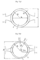
- the method proposed in the above-cited Japanese Patent Examined Publication No. H05-75485 consists in that since, in a mandrel mill in which the directions of reduction of two neighboring 2-roll stands cross with each other at an angle of 90° and the final stands does not reduce tubes but the upper 2 to 4 stands from the final ones finish reduction, deviations in thickness occur in the directions to the groove bottoms and in the directions making an angle of 45° with the groove bottoms, as shown in Fig. 6, the work sides and drive sides of the 2 to 4 finishing stands in the mandrel mill should be operated at different rolling gap so that the differences in wall thickness within the circumferential directions may be minimized geometrically.
- the number of mandrel bars 2 which a plant can keep is limited and, in practice, several kinds of steel tubes 3 differing in wall thickness are produced using the same mandrel bar 2 having a certain outside diameter.
- a tube is rolled using a mandrel bar 2 having an outside diameter differing from the ideal outside diameter and each end of the reduction rolls is closed in the same amount so that the groove bottom-to-groove bottom distance in the reduction rolls 1 may become equal to Ga, as shown in Fig.
- the deviations in thickness are reduced by the geometrical calculation. In reality, however, greater deviations in thickness than the deviations given by calculations occur due to deviations in equipment installation and uneven wear of reduction rolls.
- the method proposed in the Japanese Patent Examined Publication No. H05-75485 has a problem in that the deviations in thickness occurring after setting of the mandrel mill has not been taken into consideration at all.
- the method of producing seamless steel tubes which comprises measuring the wall thicknesses within the circumferential directions of a seamless steel tube rolled in a production line comprising a mandrel mill, in which a plurality of reduction stands with reduction rolls are disposed in succession with the directions of reduction varied each other, and controlling separately and individually, based on the results of the measurement, the positions of both ends of each axis of the reduction rolls at least in the final reduction stands of the mandrel mill so that the deviations in wall thickness can be minimized.
- the method of producing seamless steel tubes which comprises measuring the wall thicknesses within the circumferential directions of a seamless steel tube rolled in a production line comprising a mandrel mill, in which a plurality of reduction stands with reduction rolls are disposed in succession with the directions of reduction varied each other, and controlling separately and individually, based on the results of the measurement, the positions of both ends of each axis of the reduction rolls at least in the final reduction stands of the mandrel mill so that the deviations in wall thickness can be minimized.
- the wall thicknesses, at a plurality of positions within the circumferential directions, of a steel tube produced are measured, and positions of the both ends of each axis of the reduction rolls are controlled separately and individually in the manner of feedback at least in the final reduction stands of the mandrel mill to thereby make the thicker portions thinner and the thinner portions thicker, so that the deviation in thickness at any place within the circumferential direction can be controlled effectively, irrespective of the direction of reduction.
- the measurements of the wall thicknesses within the circumferential direction of the produced steel tube may be carried out either on-line or off-line.
- on-line thickness measurements are of course desirable from the productivity viewpoint.
- off-line thickness measurements the top of the tube, for instance, is marked during rolling and, after cutting, the thicknesses within the circumferential direction are measured referring to the marking.
- To control separately and individually in carrying out the method of producing seamless steel tubes according to the invention includes not only the case in which all positions of the both ends of each axis of each roll of both upper and lower rolls are all controlled but also the case in which at least one position of at least one end or both ends of the axis of at least one roll of the reduction stand is controlled. It is a matter of course that the direction of controlling includes not only the case of controlling in opposite directions on both sides of the roll but also the case of controlling in the same direction.
- Fig. 1 is a schematic illustration of a production line comprising a mandrel mill composed of a plurality of reduction stands each equipped with a pair of grooved rolls and disposed in succession.
- Fig. 2(a) is an illustration of No. 4 stand in the mandrel mill shown in Fig. 1
- Fig. 2(b) is an illustration of No. 5 stand in the mandrel mill
- Fig. 2(c) is an illustration of the channel directions of a hot wall thickness meter in the mandrel mill.
- 11 is a mandrel mill in which No. 1 to No. 5 stands (11 1 to 11 5 ) are disposed in succession with the directions of reduction in neighboring stands being varied by 90°, for instance, and 12 is a sizer comprising No. 1 to No. 12 stands (12 1 to 12 12 ). On the outlet side of No. 12 stand (12 12 ) of this sizer 12, there is disposed a hot wall thickness meter 13 having 8 measuring channel within the circumferential directions.
- the wall thicknesses within the circumferential directions of the steel tube 14 produced by the above-mentioned mandrel mill 11 and sizer 12 are measured in the on-line manner by means of the hot wall thickness meter 13.
- the thickness data obtained by the measurement are transmitted to a controller 15 and, in this controller 15, for example, the extents of groove closure of the both ends of the axis of the reduction rolls in the directions shown by boldface arrows in Figs. 2(a) and 2(b) in the paired No. 4 stand (11 4 ) and No. 5 stand (11 5 ), which are finishing stands in the mandrel mill 11, are separately and individually computed in the manner described below based on the measured thicknesses.
- the No. 4 stand (11 4 ) and No. 5 stand (11 5 ) are thus controlled in the feedback manner.
- the extents of groove closure as caused by cylinders 11aa and 11ab disposed on both sides of an upper roll 11a constituting the reduction rolls in No. 4 stand are controlled by feeding back the results of the thickness measurements in the directions of channels 3, 4 and 5 among the channels 1 to 8 shown in Fig. 2(c) which are within the thickness reduction range of the above-mentioned upper roll 11a.
- the extents of groove closure as caused by cylinders 11ba and 11bb disposed on both sides of a lower roll 11b are controlled by feeding back the results of the thickness measurements in the directions of channels 1, 8 and 7 which are within the thickness reduction range of the above-mentioned lower roll 11b.
- the extents of groove closure as caused by cylinders 11ca and 11cb disposed on both sides of an upper roll 11c constituting the passage in No. 5 stand are controlled by feeding back the results of the thickness measurements in the directions of channels 1, 2 and 3 which are within the thickness reduction range of the above-mentioned upper roll 11c.
- the extents of groove closure of both sides of a lower roll 11d are controlled by feeding back the results of the thickness measurements in the directions of channels 5, 6 and 7 which are within the thickness reduction range of the above-mentioned lower roll 11d.
- the extents of groove closure are determined in the following manner.
- wt ave (wt1 + wt2 + ... + wt8)/8
- k is equal to 2 0.5 L/R, where L is the cylinder distance and R is the roll radius (cf. Fig. 2(b)).
- L is the cylinder distance
- R is the roll radius (cf. Fig. 2(b)).
- a raw tube having an outside diameter of 435 mm and a wall thickness of 19.0 mm was subjected to rolling for stretching and wall thickness reduction in a 5-stand mandrel mill having the constitution shown in Fig. 1 to an outside diameter of 382 mm and a wall thickness of 9.0 mm, followed by sizing to an outside diameter of 323.9 mm and a wall thickness of 9.5 mm in a 1.2-stand sizer.
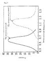
- Typical examples of the results of measurements by means of a hot wall thickness meter mean values in the lengthwise direction of the steel tube as obtained in this case by carrying out the method of the invention and without carrying out the same are shown below in Table 1, and in Fig. 3.
- Fig. 4 shows the changes in deviation in thickness before and after the start of cylinder control according to the invention
- No. 4 and No. 5 stands of the mandrel mill in the above example
- Fig. 5 shows the distribution of the deviations in thickness before and after the start of the same cylinder control according to the invention. It is evident that the deviations in wall thickness can be effectively suppressed by practicing the method of the invention.
- the invention makes it possible to effectively suppress or control not only the deviations in wall thickness occurring in the direction of reduction in a mandrel mill but also the derivations in thickness occurring at places deviating from the above-mentioned direction of reduction by measuring the wall thicknesses of a steel tube under manufacture, and controlling, by feedback, the extents of groove closure on both sides of each axis at least in the last two paired reduction stands separately and individually; thus, the ratio of accepted products in wall thickness inspection can be increased, and the yield of thin ⁇ walled products within the specified tolerance range can be improved.
Landscapes
- Engineering & Computer Science (AREA)
- Mechanical Engineering (AREA)
- Control Of Metal Rolling (AREA)
- Moulding By Coating Moulds (AREA)
Abstract
measuring the wall thicknesses within the circumferential directions of a seamless steel tube 14 rolled in a production line comprising a mandrel mill 11 consisting of a plurality of reduction stands 111 to 115 having reduction rolls disposed in succession with the directions of reduction varied each other, and controlling, separately and individually based on the results of the measurement, the positions of both ends of each axis of the reduction rolls 114 , 115 in the final reduction stands of the mandrel mill 11 so that the deviations in wall thickness can be minimized.
Description
the following controlled variable dcb for the cylinder 11cb:
| | | | | | | | Channel 8 | |
| Invention not practiced | 10.21 | 9.43 | 8.75 | 9.35 | 10.16 | 9.53 | 8.82 | 9.79 |
| Invention practiced | 9.89 | 9.70 | 9.62 | 9.43 | 9.36 | 9.50 | 9.40 | 9.42 |
| (in mm) |
| No. 4 stand | Upper roll | 11aa | +0.69 |
| 11ab | -1.26 | ||
| Lower roll | 11ba | -0.84 | |
| 11bb | +1.15 | ||
| No. 5 stand | Upper roll | 11ca | +0.92 |
| 11cb | -0.97 | ||
| Lower roll | 11da | -0.95 | |
| 11db | +1.10 | ||
| (in mm) |
Claims (1)
- A method of producing seamless steel tubes which comprises measuring the wall thicknesses within the circumferential directions of a seamless steel tube rolled in a production line comprising a mandrel mill, in which a plurality of reduction stands with reduction rolls are disposed in succession with the directions of reduction varied with respect to each other, and controlling separately and individually based on the results of the measurement, the positions of both ends of each axis of the reduction rolls at least in the final reduction stands of the mandrel mill so that the deviations in wall thickness can be minimized.
Applications Claiming Priority (3)
| Application Number | Priority Date | Filing Date | Title |
|---|---|---|---|
| JP2002018622A JP4003463B2 (en) | 2002-01-28 | 2002-01-28 | Seamless steel pipe manufacturing method |
| JP2002018622 | 2002-01-28 | ||
| PCT/JP2003/000751 WO2003064070A1 (en) | 2002-01-28 | 2003-01-27 | Method of manufacturing seamless steel pipe |
Publications (3)
| Publication Number | Publication Date |
|---|---|
| EP1479457A1 true EP1479457A1 (en) | 2004-11-24 |
| EP1479457A4 EP1479457A4 (en) | 2005-08-17 |
| EP1479457B1 EP1479457B1 (en) | 2006-05-24 |
Family
ID=27653903
Family Applications (1)
| Application Number | Title | Priority Date | Filing Date |
|---|---|---|---|
| EP03734615A Expired - Lifetime EP1479457B1 (en) | 2002-01-28 | 2003-01-27 | Method of manufacturing seamless steel pipe |
Country Status (11)
| Country | Link |
|---|---|
| US (1) | US7028518B2 (en) |
| EP (1) | EP1479457B1 (en) |
| JP (1) | JP4003463B2 (en) |
| CN (2) | CN1290633C (en) |
| AR (1) | AR038228A1 (en) |
| BR (1) | BR0306933B1 (en) |
| CA (1) | CA2474290C (en) |
| DE (1) | DE60305453T2 (en) |
| MX (1) | MXPA04007269A (en) |
| RU (1) | RU2276624C2 (en) |
| WO (1) | WO2003064070A1 (en) |
Cited By (2)
| Publication number | Priority date | Publication date | Assignee | Title |
|---|---|---|---|---|
| ITMI20091085A1 (en) * | 2009-06-19 | 2010-12-20 | Sms Innse Spa | PLANT FOR TUBE ROLLING. |
| US8387430B2 (en) | 2009-06-19 | 2013-03-05 | Sms Innse Spa | Tube rolling plant |
Families Citing this family (18)
| Publication number | Priority date | Publication date | Assignee | Title |
|---|---|---|---|---|
| EP1889670B1 (en) | 2003-03-14 | 2011-08-31 | Sumitomo Metal Industries, Ltd. | Manufacturing method of pipe and thickness deviation information derivation apparatus |
| DE602004031247D1 (en) * | 2003-10-07 | 2011-03-10 | Sumitomo Metal Ind | METHOD AND DEVICE FOR ADJUSTING THE FASTENING POSITION OF A ROLL FORMING A THREE ROLLED BARREL ROLL |
| JP4507193B2 (en) * | 2005-03-31 | 2010-07-21 | 住友金属工業株式会社 | Mandrel mill rolling control method |
| CN100455369C (en) * | 2005-06-30 | 2009-01-28 | 宝山钢铁股份有限公司 | Feed-forward control method for wall thickness of stretching and reducing machine |
| BRPI0614305B1 (en) | 2005-08-02 | 2020-02-18 | Nippon Steel Corporation | FAULT DETECTION APPLIANCE AND METHOD FOR A MATRIX TUBE |
| JP4501116B2 (en) * | 2005-08-02 | 2010-07-14 | 住友金属工業株式会社 | Scratch detection apparatus and method for blank tube |
| DE102006032813A1 (en) * | 2006-07-14 | 2008-01-24 | Sms Demag Ag | Device for rotational locking of the back-up roll balancing of rolling stands |
| JP4873012B2 (en) * | 2006-10-16 | 2012-02-08 | 住友金属工業株式会社 | Mandrel mill and seamless pipe manufacturing method |
| JP5212768B2 (en) | 2007-01-11 | 2013-06-19 | 新日鐵住金株式会社 | Method for determining reference position of rolling stand and perforated rolling roll |
| EP2127768B1 (en) * | 2007-02-08 | 2014-10-01 | Nippon Steel & Sumitomo Metal Corporation | Reducer pass roll and reducer |
| CN101720259A (en) * | 2007-03-30 | 2010-06-02 | 住友金属工业株式会社 | Method for producing seamless pipe and hole type roll |
| CN101711190B (en) * | 2007-03-30 | 2011-10-12 | 住友金属工业株式会社 | Manufacturing method of seamless pipe |
| MX2012007817A (en) * | 2010-01-05 | 2012-11-30 | Sms Innse Spa | Tube rolling plant. |
| EP2878390B1 (en) * | 2012-07-24 | 2018-01-31 | Nippon Steel & Sumitomo Metal Corporation | Seamless metal tube fabrication method |
| DE102014203422B3 (en) * | 2014-02-26 | 2015-06-03 | Sms Meer Gmbh | Method and computer program for analyzing the wall thickness distribution of a pipe |
| CN104084428B (en) * | 2014-06-11 | 2016-04-20 | 攀钢集团成都钢钒有限公司 | Subtract the uneven method thickened of sizing production On-line Control seamless steel pipe tube wall |
| DE102014110980B4 (en) * | 2014-08-01 | 2017-10-26 | Vallourec Deutschland Gmbh | Method for producing hot-rolled seamless tubes with thickened ends |
| DE102018217378B3 (en) * | 2018-10-11 | 2020-03-26 | Sms Group Gmbh | Wall thickness control when reducing pipe stretch |
Family Cites Families (15)
| Publication number | Priority date | Publication date | Assignee | Title |
|---|---|---|---|---|
| US1858990A (en) * | 1928-04-16 | 1932-05-17 | Globe Steel Tubes Co | Method of and means for rolling seamless tubing |
| US3587263A (en) * | 1968-12-10 | 1971-06-28 | Westinghouse Electric Corp | Method and apparatus for steering strip material through rolling mills |
| JPS5717318A (en) * | 1980-07-04 | 1982-01-29 | Sumitomo Metal Ind Ltd | Rolling method for metallic pipe |
| JPS617010A (en) * | 1984-06-20 | 1986-01-13 | Sumitomo Metal Ind Ltd | Method for diagnosing factor for thickness deviation of seamless pipe |
| JPS6139127A (en) * | 1984-07-31 | 1986-02-25 | Nec Corp | Data transfer system |
| JPS6174719A (en) * | 1984-09-21 | 1986-04-17 | Ishikawajima Harima Heavy Ind Co Ltd | Mandrel mill rolling method and its equipment |
| JPS6186020A (en) * | 1984-10-04 | 1986-05-01 | Kawasaki Steel Corp | Mandrel mill roll reduction control method and device |
| JPS62124007A (en) * | 1985-11-20 | 1987-06-05 | Kawasaki Steel Corp | Stretching length control method for stretch reducer |
| US4819507A (en) * | 1987-01-14 | 1989-04-11 | Societe Redex | Device for simultaneously driving the screws of two parallel screw-and-nut systems |
| JPS63230214A (en) * | 1987-03-17 | 1988-09-26 | Sumitomo Metal Ind Ltd | Pipe rolling control method |
| JPH0575485A (en) | 1991-09-10 | 1993-03-26 | Fujitsu Ltd | High frequency module |
| JPH0871616A (en) * | 1994-09-01 | 1996-03-19 | Sumitomo Metal Ind Ltd | Seamless pipe rolling apparatus and rolling control method |
| DE19611782C2 (en) * | 1996-03-13 | 1999-08-19 | Mannesmann Ag | Method and device for producing a hollow body from solid round steel |
| JP3082673B2 (en) * | 1996-06-26 | 2000-08-28 | 住友金属工業株式会社 | Rolling method of seamless steel pipe |
| JP3743609B2 (en) * | 2000-04-13 | 2006-02-08 | 住友金属工業株式会社 | Seamless pipe rolling apparatus and rolling control method |
-
2002
- 2002-01-28 JP JP2002018622A patent/JP4003463B2/en not_active Expired - Fee Related
-
2003
- 2003-01-24 AR ARP030100219A patent/AR038228A1/en active IP Right Grant
- 2003-01-27 MX MXPA04007269A patent/MXPA04007269A/en active IP Right Grant
- 2003-01-27 RU RU2004126230/02A patent/RU2276624C2/en not_active IP Right Cessation
- 2003-01-27 CN CN03802259.1A patent/CN1290633C/en not_active Expired - Fee Related
- 2003-01-27 WO PCT/JP2003/000751 patent/WO2003064070A1/en not_active Ceased
- 2003-01-27 CA CA002474290A patent/CA2474290C/en not_active Expired - Fee Related
- 2003-01-27 CN CNB2006101647372A patent/CN100464885C/en not_active Expired - Fee Related
- 2003-01-27 BR BRPI0306933-8B1A patent/BR0306933B1/en not_active IP Right Cessation
- 2003-01-27 DE DE60305453T patent/DE60305453T2/en not_active Expired - Lifetime
- 2003-01-27 EP EP03734615A patent/EP1479457B1/en not_active Expired - Lifetime
- 2003-09-26 US US10/670,193 patent/US7028518B2/en not_active Expired - Lifetime
Cited By (2)
| Publication number | Priority date | Publication date | Assignee | Title |
|---|---|---|---|---|
| ITMI20091085A1 (en) * | 2009-06-19 | 2010-12-20 | Sms Innse Spa | PLANT FOR TUBE ROLLING. |
| US8387430B2 (en) | 2009-06-19 | 2013-03-05 | Sms Innse Spa | Tube rolling plant |
Also Published As
| Publication number | Publication date |
|---|---|
| DE60305453D1 (en) | 2006-06-29 |
| CN100464885C (en) | 2009-03-04 |
| EP1479457B1 (en) | 2006-05-24 |
| RU2276624C2 (en) | 2006-05-20 |
| JP4003463B2 (en) | 2007-11-07 |
| MXPA04007269A (en) | 2004-10-29 |
| CA2474290A1 (en) | 2003-08-07 |
| EP1479457A4 (en) | 2005-08-17 |
| US7028518B2 (en) | 2006-04-18 |
| US20040065133A1 (en) | 2004-04-08 |
| CN1615189A (en) | 2005-05-11 |
| BR0306933A (en) | 2004-11-09 |
| CN1951588A (en) | 2007-04-25 |
| CA2474290C (en) | 2009-04-07 |
| BR0306933B1 (en) | 2013-07-02 |
| CN1290633C (en) | 2006-12-20 |
| JP2003220403A (en) | 2003-08-05 |
| RU2004126230A (en) | 2005-06-10 |
| AR038228A1 (en) | 2005-01-05 |
| WO2003064070A1 (en) | 2003-08-07 |
| DE60305453T2 (en) | 2007-05-10 |
Similar Documents
| Publication | Publication Date | Title |
|---|---|---|
| EP1479457B1 (en) | Method of manufacturing seamless steel pipe | |
| US7174761B2 (en) | Method of manufacturing a seamless pipe | |
| JP7184109B2 (en) | Seamless steel pipe rolling control method and manufacturing method | |
| JP4356074B2 (en) | Method and apparatus for adjusting the rolling position of a rolling roll constituting a 3-roll mandrel mill | |
| CN100411759C (en) | Method and device for adjusting roll pressing position of 3-roll mandrel mill | |
| US20120125068A1 (en) | Method for producing seamless tubes by means of a three-roll bar rolling mill | |
| JP2021098215A (en) | Seamless steel pipe manufacturing method | |
| CN113458154B (en) | Production method for preventing camber in wide and thick plate rolling process | |
| JP3339434B2 (en) | Rolling method of metal tube | |
| EP2366467A1 (en) | Rolling control method, rolling control apparatus and control program for a mandrel mill, and a method of manufacturing a seamless tube or pipe | |
| KR101917459B1 (en) | Apparatus for correcting sheet material and method of fabricating sheet material | |
| JP7205459B2 (en) | Method for detecting shape defects in steel sheet pile rolling and method for manufacturing steel sheet piles | |
| JP3487276B2 (en) | Constant diameter rolling device and constant diameter rolling method for metal tube | |
| RU2246364C2 (en) | Method for preparing rolls of pilger mills for hot rolling of tubes | |
| JP3211710B2 (en) | Manufacturing method of section steel | |
| SK286191A3 (en) | Rolling train for extensioning of hollow bodies on mandrel rod | |
| JP3211709B2 (en) | Manufacturing method of section steel | |
| JPH0576368B2 (en) | ||
| JP4418617B2 (en) | Metal tube rolling method | |
| SU1080890A1 (en) | Method of correcting the adjustment of screw rolling mill | |
| RU2288060C2 (en) | Method for preparing and calibrating rolls of pilger mill | |
| JP2005138142A (en) | Method for constant diameter rolling of metal tubes | |
| JPH06218413A (en) | Method for controlling/rolling deviation of web center of h-shape steel and h-shape steel guiding device therefor | |
| JPS61162202A (en) | Manufacture of h-beam with less center-deviation of flange |
Legal Events
| Date | Code | Title | Description |
|---|---|---|---|
| PUAI | Public reference made under article 153(3) epc to a published international application that has entered the european phase |
Free format text: ORIGINAL CODE: 0009012 |
|
| 17P | Request for examination filed |
Effective date: 20040823 |
|
| AK | Designated contracting states |
Kind code of ref document: A1 Designated state(s): AT BE BG CH CY CZ DE DK EE ES FI FR GB GR HU IE IT LI LU MC NL PT SE SI SK TR |
|
| AX | Request for extension of the european patent |
Extension state: AL LT LV MK RO |
|
| A4 | Supplementary search report drawn up and despatched |
Effective date: 20050706 |
|
| RIC1 | Information provided on ipc code assigned before grant |
Ipc: 7B 21B 17/04 B Ipc: 7B 21B 37/78 A |
|
| GRAP | Despatch of communication of intention to grant a patent |
Free format text: ORIGINAL CODE: EPIDOSNIGR1 |
|
| GRAS | Grant fee paid |
Free format text: ORIGINAL CODE: EPIDOSNIGR3 |
|
| GRAA | (expected) grant |
Free format text: ORIGINAL CODE: 0009210 |
|
| AK | Designated contracting states |
Kind code of ref document: B1 Designated state(s): DE FR GB IT |
|
| PG25 | Lapsed in a contracting state [announced via postgrant information from national office to epo] |
Ref country code: IT Free format text: LAPSE BECAUSE OF FAILURE TO SUBMIT A TRANSLATION OF THE DESCRIPTION OR TO PAY THE FEE WITHIN THE PRESCRIBED TIME-LIMIT;WARNING: LAPSES OF ITALIAN PATENTS WITH EFFECTIVE DATE BEFORE 2007 MAY HAVE OCCURRED AT ANY TIME BEFORE 2007. THE CORRECT EFFECTIVE DATE MAY BE DIFFERENT FROM THE ONE RECORDED. Effective date: 20060524 |
|
| REG | Reference to a national code |
Ref country code: GB Ref legal event code: FG4D |
|
| REF | Corresponds to: |
Ref document number: 60305453 Country of ref document: DE Date of ref document: 20060629 Kind code of ref document: P |
|
| ET | Fr: translation filed | ||
| PLBE | No opposition filed within time limit |
Free format text: ORIGINAL CODE: 0009261 |
|
| STAA | Information on the status of an ep patent application or granted ep patent |
Free format text: STATUS: NO OPPOSITION FILED WITHIN TIME LIMIT |
|
| 26N | No opposition filed |
Effective date: 20070227 |
|
| REG | Reference to a national code |
Ref country code: GB Ref legal event code: 732E Free format text: REGISTERED BETWEEN 20131010 AND 20131016 |
|
| REG | Reference to a national code |
Ref country code: FR Ref legal event code: TP Owner name: NIPPON STEEL & SUMITOMO METAL CORPORATION, JP Effective date: 20131108 |
|
| REG | Reference to a national code |
Ref country code: DE Ref legal event code: R082 Ref document number: 60305453 Country of ref document: DE Representative=s name: LOUIS, POEHLAU, LOHRENTZ, DE |
|
| REG | Reference to a national code |
Ref country code: DE Ref legal event code: R082 Ref document number: 60305453 Country of ref document: DE Representative=s name: LOUIS, POEHLAU, LOHRENTZ, DE Effective date: 20140402 Ref country code: DE Ref legal event code: R081 Ref document number: 60305453 Country of ref document: DE Owner name: NIPPON STEEL & SUMITOMO METAL CORPORATION, JP Free format text: FORMER OWNER: SUMITOMO METAL INDUSTRIES, LTD., OSAKA, JP Effective date: 20140402 |
|
| REG | Reference to a national code |
Ref country code: FR Ref legal event code: PLFP Year of fee payment: 14 |
|
| REG | Reference to a national code |
Ref country code: FR Ref legal event code: PLFP Year of fee payment: 15 |
|
| REG | Reference to a national code |
Ref country code: FR Ref legal event code: PLFP Year of fee payment: 16 |
|
| REG | Reference to a national code |
Ref country code: DE Ref legal event code: R082 Ref document number: 60305453 Country of ref document: DE Representative=s name: LOUIS, POEHLAU, LOHRENTZ, DE Ref country code: DE Ref legal event code: R081 Ref document number: 60305453 Country of ref document: DE Owner name: NIPPON STEEL CORPORATION, JP Free format text: FORMER OWNER: NIPPON STEEL & SUMITOMO METAL CORPORATION, TOKYO, JP |
|
| PGFP | Annual fee paid to national office [announced via postgrant information from national office to epo] |
Ref country code: FR Payment date: 20191216 Year of fee payment: 18 |
|
| PGFP | Annual fee paid to national office [announced via postgrant information from national office to epo] |
Ref country code: DE Payment date: 20200114 Year of fee payment: 18 Ref country code: GB Payment date: 20200115 Year of fee payment: 18 Ref country code: IT Payment date: 20200114 Year of fee payment: 18 |
|
| REG | Reference to a national code |
Ref country code: DE Ref legal event code: R119 Ref document number: 60305453 Country of ref document: DE |
|
| GBPC | Gb: european patent ceased through non-payment of renewal fee |
Effective date: 20210127 |
|
| PG25 | Lapsed in a contracting state [announced via postgrant information from national office to epo] |
Ref country code: FR Free format text: LAPSE BECAUSE OF NON-PAYMENT OF DUE FEES Effective date: 20210131 |
|
| PG25 | Lapsed in a contracting state [announced via postgrant information from national office to epo] |
Ref country code: DE Free format text: LAPSE BECAUSE OF NON-PAYMENT OF DUE FEES Effective date: 20210803 Ref country code: GB Free format text: LAPSE BECAUSE OF NON-PAYMENT OF DUE FEES Effective date: 20210127 |
|
| PG25 | Lapsed in a contracting state [announced via postgrant information from national office to epo] |
Ref country code: IT Free format text: LAPSE BECAUSE OF NON-PAYMENT OF DUE FEES Effective date: 20210127 |