EP1479129B1 - Inflatable reflector antenna for space based radars - Google Patents
Inflatable reflector antenna for space based radars Download PDFInfo
- Publication number
- EP1479129B1 EP1479129B1 EP03743677A EP03743677A EP1479129B1 EP 1479129 B1 EP1479129 B1 EP 1479129B1 EP 03743677 A EP03743677 A EP 03743677A EP 03743677 A EP03743677 A EP 03743677A EP 1479129 B1 EP1479129 B1 EP 1479129B1
- Authority
- EP
- European Patent Office
- Prior art keywords
- feed array
- catenary
- feed
- support frame
- antenna according
- Prior art date
- Legal status (The legal status is an assumption and is not a legal conclusion. Google has not performed a legal analysis and makes no representation as to the accuracy of the status listed.)
- Expired - Lifetime
Links
- 238000000576 coating method Methods 0.000 claims description 12
- 239000011248 coating agent Substances 0.000 claims description 11
- 239000012528 membrane Substances 0.000 description 9
- 239000000758 substrate Substances 0.000 description 2
- 229920002799 BoPET Polymers 0.000 description 1
- 239000005041 Mylar™ Substances 0.000 description 1
- 230000004075 alteration Effects 0.000 description 1
- 230000015556 catabolic process Effects 0.000 description 1
- 238000006731 degradation reaction Methods 0.000 description 1
- 230000000694 effects Effects 0.000 description 1
- 238000005516 engineering process Methods 0.000 description 1
- 239000000835 fiber Substances 0.000 description 1
- 239000012634 fragment Substances 0.000 description 1
- 238000005286 illumination Methods 0.000 description 1
- 238000004519 manufacturing process Methods 0.000 description 1
- 239000000463 material Substances 0.000 description 1
- 239000002184 metal Substances 0.000 description 1
- 230000000116 mitigating effect Effects 0.000 description 1
- 238000004806 packaging method and process Methods 0.000 description 1
- 229920003023 plastic Polymers 0.000 description 1
- 229920003223 poly(pyromellitimide-1,4-diphenyl ether) Polymers 0.000 description 1
- 238000001556 precipitation Methods 0.000 description 1
- 238000010008 shearing Methods 0.000 description 1
Images


Classifications
-
- H—ELECTRICITY
- H01—ELECTRIC ELEMENTS
- H01Q—ANTENNAS, i.e. RADIO AERIALS
- H01Q1/00—Details of, or arrangements associated with, antennas
- H01Q1/08—Means for collapsing antennas or parts thereof
- H01Q1/081—Inflatable antennas
- H01Q1/082—Balloon antennas
-
- H—ELECTRICITY
- H01—ELECTRIC ELEMENTS
- H01Q—ANTENNAS, i.e. RADIO AERIALS
- H01Q1/00—Details of, or arrangements associated with, antennas
- H01Q1/08—Means for collapsing antennas or parts thereof
- H01Q1/081—Inflatable antennas
-
- H—ELECTRICITY
- H01—ELECTRIC ELEMENTS
- H01Q—ANTENNAS, i.e. RADIO AERIALS
- H01Q1/00—Details of, or arrangements associated with, antennas
- H01Q1/27—Adaptation for use in or on movable bodies
- H01Q1/28—Adaptation for use in or on aircraft, missiles, satellites, or balloons
- H01Q1/288—Satellite antennas
-
- H—ELECTRICITY
- H01—ELECTRIC ELEMENTS
- H01Q—ANTENNAS, i.e. RADIO AERIALS
- H01Q15/00—Devices for reflection, refraction, diffraction or polarisation of waves radiated from an antenna, e.g. quasi-optical devices
- H01Q15/14—Reflecting surfaces; Equivalent structures
- H01Q15/16—Reflecting surfaces; Equivalent structures curved in two dimensions, e.g. paraboloidal
- H01Q15/161—Collapsible reflectors
- H01Q15/163—Collapsible reflectors inflatable
-
- H—ELECTRICITY
- H01—ELECTRIC ELEMENTS
- H01Q—ANTENNAS, i.e. RADIO AERIALS
- H01Q19/00—Combinations of primary active antenna elements and units with secondary devices, e.g. with quasi-optical devices, for giving the antenna a desired directional characteristic
- H01Q19/10—Combinations of primary active antenna elements and units with secondary devices, e.g. with quasi-optical devices, for giving the antenna a desired directional characteristic using reflecting surfaces
- H01Q19/12—Combinations of primary active antenna elements and units with secondary devices, e.g. with quasi-optical devices, for giving the antenna a desired directional characteristic using reflecting surfaces wherein the surfaces are concave
- H01Q19/17—Combinations of primary active antenna elements and units with secondary devices, e.g. with quasi-optical devices, for giving the antenna a desired directional characteristic using reflecting surfaces wherein the surfaces are concave the primary radiating source comprising two or more radiating elements
- H01Q19/175—Combinations of primary active antenna elements and units with secondary devices, e.g. with quasi-optical devices, for giving the antenna a desired directional characteristic using reflecting surfaces wherein the surfaces are concave the primary radiating source comprising two or more radiating elements arrayed along the focal line of a cylindrical focusing surface
Definitions
- the disclosed invention relates generally to antenna systems, and more particularly to an inflated reflector antenna structure.
- Space deployable antenna structures include metal mesh designs that are heavy, bulky, difficult to package and deploy, and generally expensive to construct. Further, such mesh antennas would be difficult to implement as large antennas.
- Other space deployable antenna structures include inflatable antennas wherein an inflatable structure forms a reflective surface.
- Known inflatable antenna structures have an antenna profile that tends to change, which impairs the properties of the antenna.
- An antenna which includes an inflatable flexible enclosed envelope having a curved wall transparent to RF, the curved wall ending at first and second opposing edges.
- An RF reflective coating is disposed on the curved wall.
- a catenary support frame supports the first and second edges and maintains the curved wall in a predetermined shape when the envelope is inflated.
- a support structure is provided to support a feed array illuminating the RF reflective coating with RF energy.
- FIG. 1 illustrates an exemplary embodiment of an inflatable antenna structure in accordance with aspects of the invention.
- FIG. 1 is a schematic perspective view of an inflatable antenna structure that generally includes a pillow shaped inflatable envelope 20 formed of a thin flexible RF transparent plastic membrane, such as .3 mil thick Kapton (TM), and having a rear curved wall 11 and a front curved wall 13 (FIG. 2). The shape of the inflatable envelope is maintained by inflating gas and a catenary and strut frame as described further herein.
- An X-band and L-band feed array 30 and a bus 40 are supported in front of the front curved wall 13.
- an RF transparent, high emissivity black coating 16 such as an ink coating
- An RF reflecting coating 17 is disposed on the outside of the rear curved wall 11, while an RF transparent solar energy reflective coating 19 can be disposed on the front curved wall 13.
- the RF reflecting coating 17 can be for example a plurality of metallized layers for RF reflection.
- the front and rear curved walls are cylindrical and have parallel cylinder axes.
- the front and rear curved walls therefore intersect and are joined along substantially parallel opposing edges 15 which for reference can be considered as being horizontal and along an X-axis of an XYZ coordinate system as shown in FIG. 1.
- the interface between the RF reflecting coating and the rear wall 11 thus forms a reflector having a circular cross section in the elevation plane (EL) which is parallel to the YZ plane.
- the cylindrical contour in the elevation plane is maintained by gas pressure, and Y-axis reflector struts 21, each located between opposing ends of the edges 15, absorb cylindrical flattening forces.
- the Y-axis reflector struts are parallel to the Y-axis and can more particularly be inflatable, non-conductive, rigidizable tubes.
- the reflector surface is flattened off-cylindrical by catenary hanger structures along the horizontal or X-axis.
- Each catenary hanger structure includes, for example, a catenary wire 23 and a catenary mesh web or membrane 25 that are connected between an edge 15 and ends of an X-axis strut or longeron 27 that absorbs an X-axis force created by the catenary hanger structure.
- Each catenary wire 23 is more particularly connected along its length to a contoured edge of the membrane 25 that maintains an accurate shape in the wire.
- the opposing edge of the membrane 25 is linear, and connects to the junction of the curved walls 11, 13.
- the wire 23 and the membrane 25 are preferably made of low coefficient of thermal expansion materials to maintain an accurate shape in the wire at expected temperatures.
- a micrometeriod shield 28 (FIG. 2) is disposed in the envelope 20 and extends between the opposing edges 15, and can also assist in maintaining linearity of the edges 15.
- the shield 28 comprises a membrane such as 0.25 mil thick Mylar (TM) to absorb or slow down the fragmented pieces of a micrometeor that penetrates one of the curved walls, mitigating damage and the resulting inflatant leak rate that would otherwise occur as the fragments impact one of the curved walls on the way out of the envelope.
- TM 0.25 mil thick Mylar
- the feed array 30 is supported along the horizontal and vertical axes by a feed array support structure 31 comprising a catenary frame 34 that includes X-axis or horizontal feed longerons 32 on opposite sides of the feed array 30 and plurality of vertical cross-bars 33 that span between the longerons 32.
- Catenary hanger structures comprising catenary wires 37 and catenary mesh web or membrane 35 are disposed between an edge of the feed array 30 and the catenary frame 34.
- the catenary wires 37 are suspended at the interconnections of the X-axis feed longerons 32 and the cross-bars 33, and each is connected along its length to a contoured edge of an associated catenary membrane 35 that has an opposing linear edge attached to an edge of the feed array.
- the catenary wires 37 and the catenary membranes 35 can be made of low coefficient of thermal expansion fibers to maintain a near accurate shape at expected operating temperatures.
- the feed array 30 in an exemplary embodiment is a Z-folded structure, fabricated on a flexible dielectric substrate such as a flexible circuit board structure to permit the folding. Rows and columns of radiating elements are fabricated on the substrate, and can comprise RF patch elements. Each column is aligned in the Y-axis, with the rows aligned in the X-axis.
- the feed array assembly comprising the feed array 30 and the catenary supporting frame 34 is connected to the reflector supporting frame by a pair of W-trusses, each comprising outer struts 41 (FIG. 1) connected between the ends of the feed array longerons 32 and the ends of the reflector longerons 27 and diagonal struts 43 connected between the centers of the feed array longerons 32 and the ends of the reflector longerons 27.
- Support wires 45 are connected between ends of the feed array longerons 32 and corresponding ends of the reflector longeron 27 that are further away vertically. These wires provide for stiffening against shearing.
- the longerons, struts, and cross-bars of the antenna structure preferably comprise rigidizable collapsed elements that are extended and rigidized when the antenna structure is deployed in space, for example by jettison from a launch vehicle such as an Atlas II rocket, using an expanded payload fairing.
- the reflector longerons 27 can comprise inflatable, rigidizable members.
- the reflector Y-axis struts 21 and the diagonal struts 43 comprise inflatable, rigidizable, Z-folded members.
- the feed X-axis longerons 31 and the outer struts 41 can comprise inflatable, rigidizable members.
- the feed cross-bars 33 can comprise inflatable, rigidizable, Z-folded members.
- the rear curved surface 11 of the inflated envelope 20 and the RF reflective coating 17 thereon form a cylindrical reflector 200 of circular cross section having for example a radius R of about 55 meters.
- the reflector 200 can be oversized to support elevation (EL) and azimuth (AZ) scans.
- the reflector is about 65 meters in height H (FIG. 4) in the elevation plane which is parallel to the YZ plane and 60 meters in length L (FIG. 1) in the azimuth plane which is parallel to the XZ plane.
- the active feed array 30 is about 50 meters in length FL and about 1 meter in height FH, and for reasons discussed further herein is more particularly located about half way between the vertex of the reflector 200 and the center of the circular antenna.
- the feed array 30 is supported on a radial arc equal in radius to that of the reflector 200, but for many applications, a planar feed array can be employed.
- an aperture length AL (FIG. 1) of about 50 meters in the azimuth plane is employed.
- AH slightly greater aperture height
- An aperture taper of 10 dB is imposed in both the elevation and azimuth planes to control the side lobes.
- Beam scan in the elevation plane is accomplished by "rocking" (rotating) the beam with respect to the center of the circular reflector. This is done by selectively turning on/off some of the radiating elements at the top and bottom of the feed array in the Y-axis.
- the number of radiating elements in the Y-axis needed for operation at a given pointing direction is fewer that the number of elements forming each column.
- the illumination pattern of the array feed will move up and down by about 5 meters, and a reflector height H (FIG. 4) of about 65 meters is selected to capture all the scanned beams.
- Circular symmetry provides uniform scan performance in the EL scan.
- Linear geometry in the AZ plane minimizes the packaging, deployment, and feed design.
- Cylindrical instead of spherical geometry reduces power density of the transmit modules.
- Symmetrical and cylindrical configuration greatly simplifies inflatable design and fabrication, and hence substantially reducing overall cost.
- a first step in the design of the exemplary embodiment is to select a proper radius for a given aperture size, which is constrained by the specified EL beam width.
- a long focal length F reduces aberration, (phase errors) and the focal spot size, which also results in a better-behaved (smooth) phase front in the focal region.
- a more uniform phase distribution is easier to match, and a small, but not too small, focal spot is desired because it requires fewer rows of radiating elements to receive the focused beam.
- a long focal length F will offset the focal spot far away from the axis for the EL scan, which increases the feed size and the number of radiating elements required to populate the feed array. This will complicate the design of the commutation switch, which is used to shift the power to the active region of a moving focal spot. Moreover, it also increases aperture blockage, causing gain drop and side lobe degradation due to the scattering of the feed array.
- the optimum focal point for this exemplary embodiment is chosen to balance the spot size, power density of the focal region, the feed height, and the maximum aperture blockage allowed.
- the design guideline for this embodiment is to keep the feed less than 8 m in height, and a focal spot size around -1.5 m using a -10 dB truncation point. It was found that an optimum focal length F for this design is about 26 meters from the vertex of the reflector 200.
- the packaged antenna structure is deployed as follows, for example after jettisoning of a container that contained the collapsed antenna structure.
- the outer W-struts 41 are telescopically deployed via inflation to separate the feed array and the feed support structure from the inflatable envelope 20, as depicted in FIG. 5.
- the double Z-folded envelope 20 unfolds in the Y-axis
- the Z-folded enclosed struts 21 deploy freely
- the Z-folded diagonal W-struts 32 deploy freely.
- the X-axis feed longerons 32 and the reflector longerons 21 are then deployed via inflation, as depicted in FIG. 6. Pursuant to this deployment, the envelope 20 unfolds along the X-axis, and the bi-folded, Z-folded feed array 30 is deployed.
- the feed crossbars are inflated to tension the feed array 30, and the enclosed Y-axis reflector struts 21 and the diagonal struts 3 are inflated to complete deployment of the tubular longerons, struts, and cross bars.
- the envelope is then inflated, which will provide shear strength and maintain needed tolerances, and the tubular longerons, struts and cross bars are allowed to rigidize.
- the tubes are then evacuated through null jets. Solar panels 48 are also deployed to provide electrical power.
- the antenna can for example be employed in multi-band, co-aperture applications, at various orbit locations, and can provide service in such applications as synthetic aperture radar, space-based radars and the like.
Landscapes
- Physics & Mathematics (AREA)
- Engineering & Computer Science (AREA)
- Astronomy & Astrophysics (AREA)
- General Physics & Mathematics (AREA)
- Remote Sensing (AREA)
- Aviation & Aerospace Engineering (AREA)
- Electromagnetism (AREA)
- Aerials With Secondary Devices (AREA)
- Details Of Aerials (AREA)
Description
- The disclosed invention relates generally to antenna systems, and more particularly to an inflated reflector antenna structure.
- Space deployable antenna structures include metal mesh designs that are heavy, bulky, difficult to package and deploy, and generally expensive to construct. Further, such mesh antennas would be difficult to implement as large antennas.
- Other space deployable antenna structures include inflatable antennas wherein an inflatable structure forms a reflective surface.
- An antenna as defined by the preamble of claim 1 is disclosed by Sadowy et al., "Technologies for the next Generation of Spaceborn Precipitation Radars", 2001 IEEE Aerospace Conference Proceedings, vol. 4, pages 1811 to 1823, Big Sky, MT, USA.
- Known inflatable antenna structures have an antenna profile that tends to change, which impairs the properties of the antenna.
- An antenna is disclosed, which includes an inflatable flexible enclosed envelope having a curved wall transparent to RF, the curved wall ending at first and second opposing edges. An RF reflective coating is disposed on the curved wall. A catenary support frame supports the first and second edges and maintains the curved wall in a predetermined shape when the envelope is inflated. A support structure is provided to support a feed array illuminating the RF reflective coating with RF energy.
- These and other features and advantages of the present invention will become more apparent from the following detailed description of an exemplary embodiment thereof, as illustrated in the accompanying drawings, in which:
- FIG. 1 is a schematic perspective view of an antenna structure in accordance with the invention.
- FIG. 2 is a schematic elevational cross-sectional view depicting the coatings on walls of an inflatable envelope of the antenna structure of FIG. 1.
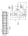
- FIG. 3 is a schematic elevational view of the feed array support structure of the antenna structure of FIG. 1.
- FIG. 4 is a schematic elevational view illustrating the operation of the antenna structure of FIG. 1.
- FIG. 5 is a schematic view illustrating a stage in the deployment of the antenna structure of FIG. 1.
- FIG. 6 is a schematic view illustrating a further stage in the deployment of the antenna structure of FIG. 1.
- FIG. 7 is a schematic view illustrating another stage in the deployment of the antenna structure of FIG. 1.
- FIG. 1 illustrates an exemplary embodiment of an inflatable antenna structure in accordance with aspects of the invention. FIG. 1 is a schematic perspective view of an inflatable antenna structure that generally includes a pillow shaped
inflatable envelope 20 formed of a thin flexible RF transparent plastic membrane, such as .3 mil thick Kapton (TM), and having a rearcurved wall 11 and a front curved wall 13 (FIG. 2). The shape of the inflatable envelope is maintained by inflating gas and a catenary and strut frame as described further herein. An X-band and L-band feed array 30 and abus 40 are supported in front of the frontcurved wall 13. - Referring now to FIG. 2, an RF transparent, high emissivity
black coating 16, such as an ink coating, is disposed on the inside of the rear andfront walls RF reflecting coating 17 is disposed on the outside of the rearcurved wall 11, while an RF transparent solar energyreflective coating 19 can be disposed on the frontcurved wall 13. TheRF reflecting coating 17 can be for example a plurality of metallized layers for RF reflection. - In this exemplary embodiment, the front and rear curved walls are cylindrical and have parallel cylinder axes. The front and rear curved walls therefore intersect and are joined along substantially parallel opposing
edges 15 which for reference can be considered as being horizontal and along an X-axis of an XYZ coordinate system as shown in FIG. 1. The interface between the RF reflecting coating and therear wall 11 thus forms a reflector having a circular cross section in the elevation plane (EL) which is parallel to the YZ plane. - The cylindrical contour in the elevation plane is maintained by gas pressure, and Y-
axis reflector struts 21, each located between opposing ends of theedges 15, absorb cylindrical flattening forces. The Y-axis reflector struts are parallel to the Y-axis and can more particularly be inflatable, non-conductive, rigidizable tubes. - The reflector surface is flattened off-cylindrical by catenary hanger structures along the horizontal or X-axis. Each catenary hanger structure includes, for example, a
catenary wire 23 and a catenary mesh web ormembrane 25 that are connected between anedge 15 and ends of an X-axis strut orlongeron 27 that absorbs an X-axis force created by the catenary hanger structure. Eachcatenary wire 23 is more particularly connected along its length to a contoured edge of themembrane 25 that maintains an accurate shape in the wire. The opposing edge of themembrane 25 is linear, and connects to the junction of thecurved walls wire 23 and themembrane 25 are preferably made of low coefficient of thermal expansion materials to maintain an accurate shape in the wire at expected temperatures. - A micrometeriod shield 28 (FIG. 2) is disposed in the
envelope 20 and extends between theopposing edges 15, and can also assist in maintaining linearity of theedges 15. Theshield 28 comprises a membrane such as 0.25 mil thick Mylar (TM) to absorb or slow down the fragmented pieces of a micrometeor that penetrates one of the curved walls, mitigating damage and the resulting inflatant leak rate that would otherwise occur as the fragments impact one of the curved walls on the way out of the envelope. - Referring now to FIG. 3, the
feed array 30 is supported along the horizontal and vertical axes by a feedarray support structure 31 comprising acatenary frame 34 that includes X-axis orhorizontal feed longerons 32 on opposite sides of thefeed array 30 and plurality ofvertical cross-bars 33 that span between thelongerons 32. Catenary hanger structures comprisingcatenary wires 37 and catenary mesh web ormembrane 35 are disposed between an edge of thefeed array 30 and thecatenary frame 34. Thecatenary wires 37 are suspended at the interconnections of theX-axis feed longerons 32 and thecross-bars 33, and each is connected along its length to a contoured edge of an associatedcatenary membrane 35 that has an opposing linear edge attached to an edge of the feed array. Thecatenary wires 37 and thecatenary membranes 35 can be made of low coefficient of thermal expansion fibers to maintain a near accurate shape at expected operating temperatures. - The
feed array 30 in an exemplary embodiment is a Z-folded structure, fabricated on a flexible dielectric substrate such as a flexible circuit board structure to permit the folding. Rows and columns of radiating elements are fabricated on the substrate, and can comprise RF patch elements. Each column is aligned in the Y-axis, with the rows aligned in the X-axis. - The feed array assembly comprising the
feed array 30 and the catenary supportingframe 34 is connected to the reflector supporting frame by a pair of W-trusses, each comprising outer struts 41 (FIG. 1) connected between the ends of thefeed array longerons 32 and the ends of thereflector longerons 27 anddiagonal struts 43 connected between the centers of thefeed array longerons 32 and the ends of thereflector longerons 27.Support wires 45 are connected between ends of the feed array longerons 32 and corresponding ends of thereflector longeron 27 that are further away vertically. These wires provide for stiffening against shearing. - The longerons, struts, and cross-bars of the antenna structure preferably comprise rigidizable collapsed elements that are extended and rigidized when the antenna structure is deployed in space, for example by jettison from a launch vehicle such as an Atlas II rocket, using an expanded payload fairing. For example, the
reflector longerons 27 can comprise inflatable, rigidizable members. The reflector Y-axis struts 21 and thediagonal struts 43 comprise inflatable, rigidizable, Z-folded members. The feed X-axis longerons 31 and theouter struts 41 can comprise inflatable, rigidizable members. Thefeed cross-bars 33 can comprise inflatable, rigidizable, Z-folded members. - Referring now to FIG. 4, the rear
curved surface 11 of the inflatedenvelope 20 and the RFreflective coating 17 thereon form acylindrical reflector 200 of circular cross section having for example a radius R of about 55 meters. Thereflector 200 can be oversized to support elevation (EL) and azimuth (AZ) scans. For example, the reflector is about 65 meters in height H (FIG. 4) in the elevation plane which is parallel to the YZ plane and 60 meters in length L (FIG. 1) in the azimuth plane which is parallel to the XZ plane. The following are examples of parameters for one exemplary antenna system that employs such a reflector.Frequency 1 GHz Bandwidth 5% AZ Beam width 0.3 Deg EL Beam width 0.3 Deg Scan Volume +/- 6 Deg AZ, +/- 6 Deg EL Power-Aperture 30,000 KW m2 Prime Power 32 KW Satellite Altitude Medium Earth Orbit Volume To Fit in Atlas II Mass < 1100 Kg - For this exemplary embodiment, the
active feed array 30 is about 50 meters in length FL and about 1 meter in height FH, and for reasons discussed further herein is more particularly located about half way between the vertex of thereflector 200 and the center of the circular antenna. Ideally, thefeed array 30 is supported on a radial arc equal in radius to that of thereflector 200, but for many applications, a planar feed array can be employed. To produce the specified azimuth beam width of 0.3 degree at L-band, an aperture length AL (FIG. 1) of about 50 meters in the azimuth plane is employed. For the elevation plane, however, a slightly greater aperture height AH (FIG. 4) of about 55 meters can be selected to offset the broadening effect caused by the blockage of the feed array. An aperture taper of 10 dB is imposed in both the elevation and azimuth planes to control the side lobes. - Beam scan in the elevation plane is accomplished by "rocking" (rotating) the beam with respect to the center of the circular reflector. This is done by selectively turning on/off some of the radiating elements at the top and bottom of the feed array in the Y-axis. The number of radiating elements in the Y-axis needed for operation at a given pointing direction is fewer that the number of elements forming each column. By electronically selecting the particular elements used for a particular beam in the Y-axis, e.g., by use of a commutation switch network, the beam can be rotated or scanned over a limited beamwidth. As the beam scans off axis ±6 degree in the elevation plane relative to the on-axis beam, the illumination pattern of the array feed will move up and down by about 5 meters, and a reflector height H (FIG. 4) of about 65 meters is selected to capture all the scanned beams.
- This exemplary embodiment provides the following features. Circular symmetry provides uniform scan performance in the EL scan. Linear geometry in the AZ plane minimizes the packaging, deployment, and feed design. Cylindrical instead of spherical geometry reduces power density of the transmit modules. Symmetrical and cylindrical configuration greatly simplifies inflatable design and fabrication, and hence substantially reducing overall cost.
- Ray optics shows that the focal length F of a circular reflector is about one half of its radius. Thus, a first step in the design of the exemplary embodiment is to select a proper radius for a given aperture size, which is constrained by the specified EL beam width. A long focal length F reduces aberration, (phase errors) and the focal spot size, which also results in a better-behaved (smooth) phase front in the focal region. A more uniform phase distribution is easier to match, and a small, but not too small, focal spot is desired because it requires fewer rows of radiating elements to receive the focused beam.
- On the other hand, a long focal length F will offset the focal spot far away from the axis for the EL scan, which increases the feed size and the number of radiating elements required to populate the feed array. This will complicate the design of the commutation switch, which is used to shift the power to the active region of a moving focal spot. Moreover, it also increases aperture blockage, causing gain drop and side lobe degradation due to the scattering of the feed array.
- The optimum focal point for this exemplary embodiment is chosen to balance the spot size, power density of the focal region, the feed height, and the maximum aperture blockage allowed. The design guideline for this embodiment is to keep the feed less than 8 m in height, and a focal spot size around -1.5 m using a -10 dB truncation point. It was found that an optimum focal length F for this design is about 26 meters from the vertex of the
reflector 200. - Referring now to FIGS. 5-7, the packaged antenna structure is deployed as follows, for example after jettisoning of a container that contained the collapsed antenna structure. The outer W-struts 41 are telescopically deployed via inflation to separate the feed array and the feed support structure from the
inflatable envelope 20, as depicted in FIG. 5. Pursuant to such deployment, the double Z-foldedenvelope 20 unfolds in the Y-axis, the Z-foldedenclosed struts 21 deploy freely, and the Z-folded diagonal W-struts 32 deploy freely. - The
X-axis feed longerons 32 and thereflector longerons 21 are then deployed via inflation, as depicted in FIG. 6. Pursuant to this deployment, theenvelope 20 unfolds along the X-axis, and the bi-folded, Z-foldedfeed array 30 is deployed. - The feed crossbars are inflated to tension the
feed array 30, and the enclosed Y-axis reflector struts 21 and the diagonal struts 3 are inflated to complete deployment of the tubular longerons, struts, and cross bars. The envelope is then inflated, which will provide shear strength and maintain needed tolerances, and the tubular longerons, struts and cross bars are allowed to rigidize. The tubes are then evacuated through null jets.Solar panels 48 are also deployed to provide electrical power. - While this invention has been described in the context of an exemplary embodiment with exemplary frequency and size parameters, it is to be understood that the invention is not limited to the particular parameters set out above, and can be employed for other applications and frequency regimes. The antenna can for example be employed in multi-band, co-aperture applications, at various orbit locations, and can provide service in such applications as synthetic aperture radar, space-based radars and the like.
Claims (11)
- A deployable antenna comprising: an inflatable flexible enclosed envelope (20) comprising a cylindrical wall (11),said cylindrical wall (11) transparent to RF, the wall (11) ending at first and second opposing edges (15),an RF reflective coating (17) disposed on said cylindrical wall (11),a deployable reflector support frame (21, 23, 25, 27) that when deployed supports said first and second edges (15) and maintains said cylindrical wall (11) in a cylindrical shape, when said envelope is inflated anda feed array support structure (31) connected to said support frame (21, 23, 25, 27) supporting a feed array (30) for illuminating said RF reflective coating (17) with RF energy,characterized bythe reflector support frame (21, 23, 25, 27) being a deployable catenary reflector support frame and the feed array support structure (31) being a deployable feed array support structure.
- An antenna according to claim 1 wherein said catenary reflector support frame includes catenary supports (23).
- An antenna according to claim 1, wherein said catenary reflector support frame includes extendable, rigidizable components (21, 27).
- An antenna according to any preceding claim, wherein said feed array support structure (31) includes a catenary feed array support frame (32, 33, 34) for supporting said feed array.
- An antenna according to claim 4 wherein said catenary feed support frame (31) includes extendable, rigidizable components (34, 33).
- An antenna according to any preceding claim, wherein said feed array support structure (31) further includes a deployable truss structure (41, 43) connected between said feed support structure (31) and said reflector catenary support frame (21, 23, 25, 27) for supporting the feed support frame (31) at said focal location.
- An antenna according to claim 6 wherein said truss structure includes extendable, rigidizable components (41, 43).
- An antenna according to any preceding claim, wherein said cylindrical wall (11) and said feed array support structure (31) are configured for an aperture that is about 55 meters in height and about 50 meters in length when deployed.
- An antenna according to any preceding claim, wherein said cylindrical wall (11) has a radius of about 55 meters when deployed, and said feed array (30) is located about 26 meters from a vertex of said cylindrical wall (11) when deployed.
- An antenna according to any preceding claim, further characterized in that the antenna is deployable in space.
- An antenna according to claim 10, further comprising a micrometeor shield (28) disposed within said envelope (20).
Applications Claiming Priority (3)
| Application Number | Priority Date | Filing Date | Title |
|---|---|---|---|
| US86211 | 1998-05-21 | ||
| US10/086,211 US6650304B2 (en) | 2002-02-28 | 2002-02-28 | Inflatable reflector antenna for space based radars |
| PCT/US2003/004558 WO2003075397A1 (en) | 2002-02-28 | 2003-02-13 | Inflatable reflector antenna for space based radars |
Publications (2)
| Publication Number | Publication Date |
|---|---|
| EP1479129A1 EP1479129A1 (en) | 2004-11-24 |
| EP1479129B1 true EP1479129B1 (en) | 2006-06-07 |
Family
ID=27753811
Family Applications (1)
| Application Number | Title | Priority Date | Filing Date |
|---|---|---|---|
| EP03743677A Expired - Lifetime EP1479129B1 (en) | 2002-02-28 | 2003-02-13 | Inflatable reflector antenna for space based radars |
Country Status (6)
| Country | Link |
|---|---|
| US (1) | US6650304B2 (en) |
| EP (1) | EP1479129B1 (en) |
| JP (1) | JP4202267B2 (en) |
| CA (1) | CA2451724C (en) |
| DE (1) | DE60305889T2 (en) |
| WO (1) | WO2003075397A1 (en) |
Families Citing this family (32)
| Publication number | Priority date | Publication date | Assignee | Title |
|---|---|---|---|---|
| US6963315B2 (en) * | 2003-05-05 | 2005-11-08 | Srs Technologies, Inc. | Inflatable antenna |
| US6930653B2 (en) * | 2003-05-15 | 2005-08-16 | Harris Corporation | Reflector and sub-reflector adjustment using fluidic dielectrics |
| US6873305B2 (en) * | 2003-05-15 | 2005-03-29 | Harris Corporation | Taper adjustment on reflector and sub-reflector using fluidic dielectrics |
| US6927745B2 (en) * | 2003-08-25 | 2005-08-09 | Harris Corporation | Frequency selective surfaces and phased array antennas using fluidic dielectrics |
| US7095377B2 (en) * | 2003-10-30 | 2006-08-22 | Lucent Technologies Inc. | Light-weight signal transmission lines and radio frequency antenna system |
| US7133001B2 (en) * | 2003-11-03 | 2006-11-07 | Toyon Research Corporation | Inflatable-collapsible transreflector antenna |
| US7057563B2 (en) * | 2004-05-28 | 2006-06-06 | Raytheon Company | Radiator structures |
| US7438261B2 (en) * | 2004-09-09 | 2008-10-21 | David R. Porter | Stratospheric balloon utilizing electrostatic inflation of walls |
| US7224322B1 (en) * | 2005-06-30 | 2007-05-29 | The United States Of America As Represented By The Secretary Of The Navy | Balloon antenna |
| US7170458B1 (en) * | 2005-07-06 | 2007-01-30 | Avalonrf, Inc. | Inflatable antenna system |
| EP1915494A4 (en) * | 2005-07-29 | 2017-02-01 | The Elumenati, LLC | Dual pressure inflatable structure and method |
| US7602349B2 (en) * | 2006-02-24 | 2009-10-13 | Lockheed Martin Corporation | System of stowing and deploying multiple phased arrays or combinations of arrays and reflectors |
| US7336232B1 (en) * | 2006-08-04 | 2008-02-26 | Raytheon Company | Dual band space-fed array |
| US7595760B2 (en) * | 2006-08-04 | 2009-09-29 | Raytheon Company | Airship mounted array |
| US7605767B2 (en) * | 2006-08-04 | 2009-10-20 | Raytheon Company | Space-fed array operable in a reflective mode and in a feed-through mode |
| US7764243B2 (en) * | 2006-08-16 | 2010-07-27 | Gatr Technologies | Antenna positioning system |
| US7567215B1 (en) * | 2007-10-23 | 2009-07-28 | The United States Of America As Represented By The Secretary Of The Navy | Portable and inflatable antenna device |
| US8319696B2 (en) * | 2007-12-20 | 2012-11-27 | Gatr Technologies | Positioning mechanism for a spherical object |
| US8274443B2 (en) * | 2009-03-16 | 2012-09-25 | Raytheon Company | Light weight stowable phased array lens antenna assembly |
| US9285139B2 (en) * | 2010-01-28 | 2016-03-15 | Coolearth Solar | Structure and articulation system for solar collectors |
| EP2643882B1 (en) | 2010-12-15 | 2014-04-16 | Skybox Imaging, Inc. | Integrated antenna system for imaging microsatellites |
| US9276306B2 (en) * | 2013-03-15 | 2016-03-01 | Gatr Technologies, Inc. | Automatically deployable communications system |
| CN103448923A (en) * | 2013-08-08 | 2013-12-18 | 上海卫星工程研究所 | Frequency regulation implementing method for deployable flexible appendages of satellites |
| US10263316B2 (en) * | 2013-09-06 | 2019-04-16 | MMA Design, LLC | Deployable reflectarray antenna structure |
| CN103872423B (en) * | 2014-03-28 | 2016-01-06 | 哈尔滨工业大学 | A kind of curling folding and inflatable deployment structure of inflating expanded parabolic-cylinder antenna |
| CN103964000A (en) * | 2014-05-21 | 2014-08-06 | 哈尔滨工业大学 | Expanding propelling device used for space inflatable expanding supporting arm |
| US10199711B2 (en) | 2015-05-13 | 2019-02-05 | The Arizona Board Of Regents On Behalf Of The University Of Arizona | Deployable reflector antenna |
| DE102015216243B4 (en) * | 2015-08-25 | 2017-06-22 | Fraunhofer-Gesellschaft zur Förderung der angewandten Forschung e.V. | ANTENNA ARRANGEMENT WITH SQUARE STRUCTURE |
| US10957987B2 (en) * | 2016-07-14 | 2021-03-23 | Harris Corporation | Space deployable inflatable antenna apparatus and associated methods |
| US11183768B1 (en) * | 2020-07-29 | 2021-11-23 | Eagle Technology, Llc | Dual boom deployable parabolic trough reflector |
| CN111987429B (en) * | 2020-08-03 | 2022-10-21 | 中国舰船研究设计中心 | Ultra-wideband omnidirectional radiation inflatable antenna |
| WO2022180757A1 (en) * | 2021-02-26 | 2022-09-01 | 三菱電機株式会社 | Reflector antenna apparatus |
Family Cites Families (14)
| Publication number | Priority date | Publication date | Assignee | Title |
|---|---|---|---|---|
| US3056131A (en) * | 1956-10-01 | 1962-09-25 | Collins Radio Co | Inflatable antenna |
| US3005987A (en) * | 1957-02-19 | 1961-10-24 | Westinghouse Electric Corp | Inflatable antenna assembly |
| US4608571A (en) * | 1981-03-26 | 1986-08-26 | Luly Robert A | Collapsible parabolic reflector |
| US4672389A (en) * | 1985-05-28 | 1987-06-09 | Ulry David N | Inflatable reflector apparatus and method of manufacture |
| US5132699A (en) | 1990-11-19 | 1992-07-21 | Ltv Aerospace And Defense Co. | Inflatable antenna |
| US5166696A (en) | 1990-11-20 | 1992-11-24 | Ltv Aerospace And Defense Co. | Apparatus and method for deploying an inflatable antenna |
| US5579609A (en) | 1994-06-10 | 1996-12-03 | Tracor, Inc. | Rigidizable inflatable structure |
| US6219009B1 (en) * | 1997-06-30 | 2001-04-17 | Harris Corporation | Tensioned cord/tie attachment of antenna reflector to inflatable radial truss support structure |
| US5990851A (en) | 1998-01-16 | 1999-11-23 | Harris Corporation | Space deployable antenna structure tensioned by hinged spreader-standoff elements distributed around inflatable hoop |
| US6340956B1 (en) * | 1999-11-12 | 2002-01-22 | Leland H. Bowen | Collapsible impulse radiating antenna |
| US6344835B1 (en) * | 2000-04-14 | 2002-02-05 | Harris Corporation | Compactly stowable thin continuous surface-based antenna having radial and perimeter stiffeners that deploy and maintain antenna surface in prescribed surface geometry |
| US6353421B1 (en) * | 2000-09-14 | 2002-03-05 | Ball Aerospace And Technologies Corp. | Deployment of an ellectronically scanned reflector |
| US6512496B2 (en) * | 2001-01-17 | 2003-01-28 | Asi Technology Corporation | Expandible antenna |
| US6570545B1 (en) * | 2001-12-06 | 2003-05-27 | The United States Of America As Represented By The Secretary Of The Navy | Apparatus and process for reflecting radar waves |
-
2002
- 2002-02-28 US US10/086,211 patent/US6650304B2/en not_active Expired - Lifetime
-
2003
- 2003-02-13 JP JP2003573736A patent/JP4202267B2/en not_active Expired - Fee Related
- 2003-02-13 WO PCT/US2003/004558 patent/WO2003075397A1/en active IP Right Grant
- 2003-02-13 CA CA002451724A patent/CA2451724C/en not_active Expired - Fee Related
- 2003-02-13 DE DE60305889T patent/DE60305889T2/en not_active Expired - Lifetime
- 2003-02-13 EP EP03743677A patent/EP1479129B1/en not_active Expired - Lifetime
Also Published As
| Publication number | Publication date |
|---|---|
| EP1479129A1 (en) | 2004-11-24 |
| CA2451724C (en) | 2008-04-29 |
| JP2005519510A (en) | 2005-06-30 |
| DE60305889D1 (en) | 2006-07-20 |
| WO2003075397A1 (en) | 2003-09-12 |
| DE60305889T2 (en) | 2007-06-14 |
| JP4202267B2 (en) | 2008-12-24 |
| US20030160733A1 (en) | 2003-08-28 |
| US6650304B2 (en) | 2003-11-18 |
| CA2451724A1 (en) | 2003-09-12 |
Similar Documents
| Publication | Publication Date | Title |
|---|---|---|
| EP1479129B1 (en) | Inflatable reflector antenna for space based radars | |
| Huang | The development of inflatable array antennas | |
| US6963315B2 (en) | Inflatable antenna | |
| EP1987604B1 (en) | System of stowing and deploying multiple phased arrays or combinations of arrays and reflectors | |
| Huang | Capabilities of printed reflectarray antennas | |
| US20070146227A1 (en) | Deployment booms | |
| GB2455311A (en) | Deployable panel structure | |
| Kelly | A scalable deployable high gain antenna-DaHGR | |
| Rusch | The current state of the reflector antenna art | |
| KR20200031095A (en) | Phased array antennas and devices that combine these phased array antennas | |
| Decrossas et al. | Deployable circularly polarized UHF printed loop antenna for mars cube one (MarCO) CubeSat | |
| Rogers et al. | Technology assessment and development of large deployable antennas | |
| Huang et al. | Inflatable microstrip reflectarray antennas at X and Ka-band frequencies | |
| US20060227048A1 (en) | Electronic pitch over mechanical roll antenna | |
| Higuchi et al. | Structure of high precision large deployable reflector for space VLBI | |
| US6388637B1 (en) | Wide band, wide scan antenna for space borne applications | |
| Huang et al. | The development of inflatable array antennas | |
| Chahat et al. | One Meter Reflectarray Antenna: OMERA | |
| Pearson et al. | Thin film antenna development and optimization | |
| US7548218B2 (en) | Isostatic support structure or fixed or re-orientable large size antenna reflectors | |
| US20030234746A1 (en) | Sub-reflector shaping in an unfurlable reflector antenna system | |
| Huang et al. | Recent development of printed reflectarrays at JPL | |
| Huang et al. | Spacecraft antenna research and development activities aimed at future missions | |
| Schaefer et al. | Unfurlable offset antenna design for multipurpose applications | |
| Sikora | FLAPS reflector antennas |
Legal Events
| Date | Code | Title | Description |
|---|---|---|---|
| PUAI | Public reference made under article 153(3) epc to a published international application that has entered the european phase |
Free format text: ORIGINAL CODE: 0009012 |
|
| 17P | Request for examination filed |
Effective date: 20040127 |
|
| AK | Designated contracting states |
Kind code of ref document: A1 Designated state(s): AT BE BG CH CY CZ DE DK EE ES FI FR GB GR HU IE IT LI LU MC NL PT SE SI SK TR |
|
| RIN1 | Information on inventor provided before grant (corrected) |
Inventor name: GORDON, JONATHAN D.,C/O RAYTHEON COMPANY Inventor name: LEE, JAR J.,RAYTHEON COMPANY Inventor name: DERBES, WILLIAM |
|
| RIN1 | Information on inventor provided before grant (corrected) |
Inventor name: DERBES, WILLIAMRAYTHEON COMPANY (EO/E4/N119) Inventor name: LEE, JAR J.,RAYTHEON COMPANY Inventor name: GORDON, JONATHAN D.,C/O RAYTHEON COMPANY |
|
| 17Q | First examination report despatched |
Effective date: 20050218 |
|
| GRAP | Despatch of communication of intention to grant a patent |
Free format text: ORIGINAL CODE: EPIDOSNIGR1 |
|
| GRAS | Grant fee paid |
Free format text: ORIGINAL CODE: EPIDOSNIGR3 |
|
| GRAA | (expected) grant |
Free format text: ORIGINAL CODE: 0009210 |
|
| AK | Designated contracting states |
Kind code of ref document: B1 Designated state(s): DE FR GB |
|
| REG | Reference to a national code |
Ref country code: GB Ref legal event code: FG4D |
|
| REF | Corresponds to: |
Ref document number: 60305889 Country of ref document: DE Date of ref document: 20060720 Kind code of ref document: P |
|
| ET | Fr: translation filed | ||
| PLBE | No opposition filed within time limit |
Free format text: ORIGINAL CODE: 0009261 |
|
| STAA | Information on the status of an ep patent application or granted ep patent |
Free format text: STATUS: NO OPPOSITION FILED WITHIN TIME LIMIT |
|
| 26N | No opposition filed |
Effective date: 20070308 |
|
| REG | Reference to a national code |
Ref country code: FR Ref legal event code: PLFP Year of fee payment: 14 |
|
| REG | Reference to a national code |
Ref country code: FR Ref legal event code: PLFP Year of fee payment: 15 |
|
| REG | Reference to a national code |
Ref country code: FR Ref legal event code: PLFP Year of fee payment: 16 |
|
| PGFP | Annual fee paid to national office [announced via postgrant information from national office to epo] |
Ref country code: GB Payment date: 20180207 Year of fee payment: 16 Ref country code: DE Payment date: 20180130 Year of fee payment: 16 |
|
| PGFP | Annual fee paid to national office [announced via postgrant information from national office to epo] |
Ref country code: FR Payment date: 20180111 Year of fee payment: 16 |
|
| REG | Reference to a national code |
Ref country code: DE Ref legal event code: R119 Ref document number: 60305889 Country of ref document: DE |
|
| GBPC | Gb: european patent ceased through non-payment of renewal fee |
Effective date: 20190213 |
|
| PG25 | Lapsed in a contracting state [announced via postgrant information from national office to epo] |
Ref country code: DE Free format text: LAPSE BECAUSE OF NON-PAYMENT OF DUE FEES Effective date: 20190903 Ref country code: GB Free format text: LAPSE BECAUSE OF NON-PAYMENT OF DUE FEES Effective date: 20190213 |
|
| PG25 | Lapsed in a contracting state [announced via postgrant information from national office to epo] |
Ref country code: FR Free format text: LAPSE BECAUSE OF NON-PAYMENT OF DUE FEES Effective date: 20190228 |