EP1478871B1 - Schlauchstueck mit geraet zum erfassen der bewegung einer rohrleitungsschicht,und zugehoerige rohrleitung - Google Patents
Schlauchstueck mit geraet zum erfassen der bewegung einer rohrleitungsschicht,und zugehoerige rohrleitung Download PDFInfo
- Publication number
- EP1478871B1 EP1478871B1 EP03720610A EP03720610A EP1478871B1 EP 1478871 B1 EP1478871 B1 EP 1478871B1 EP 03720610 A EP03720610 A EP 03720610A EP 03720610 A EP03720610 A EP 03720610A EP 1478871 B1 EP1478871 B1 EP 1478871B1
- Authority
- EP
- European Patent Office
- Prior art keywords
- sensor
- fitting
- pipe
- fitting according
- sheath
- Prior art date
- Legal status (The legal status is an assumption and is not a legal conclusion. Google has not performed a legal analysis and makes no representation as to the accuracy of the status listed.)
- Expired - Lifetime
Links
- 238000006073 displacement reaction Methods 0.000 claims description 17
- 239000003550 marker Substances 0.000 claims description 5
- 238000001514 detection method Methods 0.000 claims description 4
- 238000005259 measurement Methods 0.000 claims description 4
- 239000013307 optical fiber Substances 0.000 claims description 4
- 230000005540 biological transmission Effects 0.000 claims description 3
- 230000005355 Hall effect Effects 0.000 claims description 2
- 239000000470 constituent Substances 0.000 claims description 2
- 238000002788 crimping Methods 0.000 description 11
- 238000007789 sealing Methods 0.000 description 5
- 239000012530 fluid Substances 0.000 description 4
- 239000008186 active pharmaceutical agent Substances 0.000 description 3
- 239000000696 magnetic material Substances 0.000 description 3
- 239000000463 material Substances 0.000 description 3
- 238000000034 method Methods 0.000 description 3
- VGGSQFUCUMXWEO-UHFFFAOYSA-N Ethene Chemical compound C=C VGGSQFUCUMXWEO-UHFFFAOYSA-N 0.000 description 2
- 239000005977 Ethylene Substances 0.000 description 2
- PXHVJJICTQNCMI-UHFFFAOYSA-N Nickel Chemical compound [Ni] PXHVJJICTQNCMI-UHFFFAOYSA-N 0.000 description 2
- 239000011248 coating agent Substances 0.000 description 2
- 238000000576 coating method Methods 0.000 description 2
- 238000007689 inspection Methods 0.000 description 2
- 238000004519 manufacturing process Methods 0.000 description 2
- 229920000642 polymer Polymers 0.000 description 2
- 238000004804 winding Methods 0.000 description 2
- ZOXJGFHDIHLPTG-UHFFFAOYSA-N Boron Chemical compound [B] ZOXJGFHDIHLPTG-UHFFFAOYSA-N 0.000 description 1
- VYZAMTAEIAYCRO-UHFFFAOYSA-N Chromium Chemical compound [Cr] VYZAMTAEIAYCRO-UHFFFAOYSA-N 0.000 description 1
- 229910001182 Mo alloy Inorganic materials 0.000 description 1
- 241000699666 Mus <mouse, genus> Species 0.000 description 1
- 241000699670 Mus sp. Species 0.000 description 1
- 239000002033 PVDF binder Substances 0.000 description 1
- 229910000831 Steel Inorganic materials 0.000 description 1
- 229910052770 Uranium Inorganic materials 0.000 description 1
- 229910045601 alloy Inorganic materials 0.000 description 1
- 239000000956 alloy Substances 0.000 description 1
- 229910052796 boron Inorganic materials 0.000 description 1
- 238000005260 corrosion Methods 0.000 description 1
- 230000007797 corrosion Effects 0.000 description 1
- 230000007423 decrease Effects 0.000 description 1
- 230000002950 deficient Effects 0.000 description 1
- 230000000694 effects Effects 0.000 description 1
- 238000010292 electrical insulation Methods 0.000 description 1
- 239000000835 fiber Substances 0.000 description 1
- 229910052751 metal Inorganic materials 0.000 description 1
- 239000002184 metal Substances 0.000 description 1
- 229910052759 nickel Inorganic materials 0.000 description 1
- 230000035515 penetration Effects 0.000 description 1
- 239000003208 petroleum Substances 0.000 description 1
- 229920002981 polyvinylidene fluoride Polymers 0.000 description 1
- 239000011347 resin Substances 0.000 description 1
- 229920005989 resin Polymers 0.000 description 1
- 230000035945 sensitivity Effects 0.000 description 1
- 239000010959 steel Substances 0.000 description 1
- 239000000126 substance Substances 0.000 description 1
- XLYOFNOQVPJJNP-UHFFFAOYSA-N water Substances O XLYOFNOQVPJJNP-UHFFFAOYSA-N 0.000 description 1
- 230000003313 weakening effect Effects 0.000 description 1
Images
Classifications
-
- F—MECHANICAL ENGINEERING; LIGHTING; HEATING; WEAPONS; BLASTING
- F16—ENGINEERING ELEMENTS AND UNITS; GENERAL MEASURES FOR PRODUCING AND MAINTAINING EFFECTIVE FUNCTIONING OF MACHINES OR INSTALLATIONS; THERMAL INSULATION IN GENERAL
- F16L—PIPES; JOINTS OR FITTINGS FOR PIPES; SUPPORTS FOR PIPES, CABLES OR PROTECTIVE TUBING; MEANS FOR THERMAL INSULATION IN GENERAL
- F16L33/00—Arrangements for connecting hoses to rigid members; Rigid hose-connectors, i.e. single members engaging both hoses
- F16L33/01—Arrangements for connecting hoses to rigid members; Rigid hose-connectors, i.e. single members engaging both hoses specially adapted for hoses having a multi-layer wall
Definitions
- the present invention relates to a tip for flexible pipe to convey over long distances a fluid under pressure and the case under high temperature, such as gas, oil, water or other fluids.
- the invention more specifically relates to a mouthpiece for a flexible pipe for offshore oil exploitation.
- Such conduct may be smooth inside passage when the passage is directly formed by the sealing sheath (it is then called “smooth” boron ”) or non-smooth passage (" rough bore ”) when further inside the inner sealing sheath a carcass consisting of a staple strap which serves to prevent crushing of the pipe under the external pressure.
- the ends of the pipes intended for their connections with each other or with terminal equipment, are also defined in the API 17J recommendations, and must be performed under ensuring both a good bonding and a good seal. These are generally obtained by crimping the sheath, that is to say by a partial radial penetration of a rigid element in the sheath.
- a fixing end for a flexible tubular pipe comprising a first annular portion (generally referred to as a vault the tip) on which can support a first crimping flange equipped with a crimping cone of the inner sheath and a second part annular (usually called hood) surrounding and extending towards the back the first annular part and on which can support a second crimping flange provided with a crimping cone of the sheath cooperating with a crank support back cannula, the second annular portion defining with the first annular portion a space ring in which the armor is arranged in such a way that are peeled radially from the inner sheath in order to pass around the first crimping flange and the first annular portion to be there fixed; the tip has an armor locking collar between the first crimping flange and the second crimping flange; space said ring is intended to be filled with a filling material such as that a resin that comes to
- the inner sheath or pressure sheath, is made of plastic, for example in "Coflon” ®; over time, depending on the pressure and temperature constraints acting on it, the sheath may undergo some displacement, which may lead to crimping defective in the mouthpiece. The sheath can then move, which leads to risk of leakage at the tip. It is therefore important to monitor the sheath position by regular inspection.
- Procedures for inspecting the interior of a pipe are known using "mice” inspection scanning the pipe and giving through example of video images or identifying a possible decline of the carcass by a system of eddy currents and associated sensors (see document FR 2790087 in the name of the Applicant).
- Such methods in addition to providing information on the carcass but not directly on the sheath (in the case of "rough bore” pipes), have the disadvantage of requiring the shutdown temporary operation to send the mouse in the pipe.
- the object of the invention is therefore to propose a detection method and an associated tip that do not have the aforementioned drawbacks and can provide an indication of the displacement of the pressure sheath or other layers of the pipe without the need to stop production.
- the invention achieves its goal by means of a mouthpiece according to claim 1.
- the layer to be monitored is itself equipped with minus a specific marker to which the detection sensor is sensitive.
- the sensor communicates with a signal processing device on detection signal by any means of transmission, wired or not.
- the invention therefore relates to a fastening tip for a pipe flexible tubular comprising at least, from the inside to the outside several coaxial layers and in particular a pressure sheath made of plastic material and at least one ply of tensile armor, the tip having an annular vault on which can support a flange crimping the pressure sheath, characterized in that the nozzle also includes at least one integrated displacement sensor of one of the layers of the pipe.
- the senor is a displacement sensor of the pressure sheath.
- the layer inspected may very well be the carcass, using a marker and a adequate sensor. We could thus measure the displacement of a ring stopping device (in English "stop ring") arranged at the end of the carcass and whose position is likely to be marked by the type of sensor used.
- the senor is a magnetic field sensor cooperating with at least one magnet disposed in the pressure sheath.
- several magnets are arranged in the sheath in a plane transverse to the longitudinal axis of the pipe.
- the magnetic sensor is chosen from Hall effect sensors, magnetodiode, magnetoresistance or optical fiber (Bragg grating coupled to a magnetostrictive tube), fiber optic sensors with Faraday effect.
- the sensor or sensors are housed in the annular vault of the mouthpiece.
- the sensor (s) can be connected in a wired fashion or not to a housing data collector located for example on the tip.
- the data can then be reassembled by underwater equipment coming from collect the data of the different tips periodically.
- the data can be remounted in a wired manner by optical fibers arranged inside one of the different layers flexible pipe for example. In this way, they can be treated almost permanently, thus making it possible to verify in continues the behavior of the layer that is being monitored.
- the sensor housing is connected to the outside of the mouthpiece by passages (holes, grooves) for connections, especially wired.
- the sensor housing has a protection thermal.
- the invention also relates to a flexible pipe comprising a tip provided with at least one sensor and having in one of its layers constituents whose displacement is to be detected at least one marker associated with the sensor.
- the flexible pipe comprises in one of its layers, such as the traction blanket, means of transmission (cables, wires, optical fibers) intended to transmit the information provided by the tip sensor.
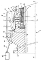
- the tip 1 symmetrical about its longitudinal axis XX ' coinciding with the central axis of the pipe, is shown in half section partial, by its connection flange 2, by its rear part fixing the driving, usually referred to as the 3-end arch and hood cylindrical 10.
- the pipe is represented by its carcass 4 and its sheath pressure 5, as well as by the inverted end 6 of its armor 7.
- the sheath 5 is set with a piece commonly called flange or cone of crimp 8 which, when pushed from the rear during assembly of the endpiece by unrepresented bodies, comes slide against a range conical of the vault 3 and bite into the sheath 5, supported here by a tapered cannula 9.
- a sacrificial sheath 21 of smaller thickness than the sheath 5 and passing under the cannula can be provided between the carcass 4 and the 5.
- the sheath 5 incorporates near its front end at minus a magnet 11.
- the arch 3 of the mouthpiece are housed (for example) three sensors 12 C1, C2, C3, arranged at a distance E from the sheath and so as to be able to detect and observe any displacement of it by the variation of the magnetic field in front of the sensors respective C1 to C3.
- the presence of three sensors makes it possible to follow the evolution of sheath displacement.
- the layout and number of sensors are also defined according to the different technical and physical parameters of the tip and the conduct like the characteristics of magnets positioned in the conduct or the nature of the steel forming the arch of the tip for example.
- the sensor (s) are introduced into the roof 3 of the mouthpiece by radial holes 13 of diameter D which opens into a groove 14 disposed in the wall of the space 15 surrounding the arch of the mouthpiece.
- a hole 16 connects the groove 14 outside, at the front of the mouthpiece.
- connection wires 17 of sensors can be brought back from the location of the sensors 12 up to a connection box 18 which can be connected by a wired link 19. or no, to a signal processing unit 20.
- the magnet (s) 11 are, for example, cylindrical magnets of small dimensions, of the order of 5 mm in length and 4 to 8 mm diameter, arranged radially in the sheath 5. They may be coated with a polymer of the polytetrafluoride type of ethylene or polyvinylidene fluoride against corrosion and for the electrical insulation carcass / vault.
- the magnets 11 are put in place in the sheath at the time of assembly of the nozzle. Yes several magnets 11 are used, they are arranged in the same plane transverse, perpendicular to the axis XX 'of the nozzle 1 and the pipe. They are circumferentially distributed at regular intervals to cover a angular sector.
- the sensors 12 for measuring the magnetic field are sensors standard of small dimensions (diameter less than 3 or 4 mm). There are such sensors that withstand without particular precaution a temperature of 150 ° C. Otherwise, they must be thermally insulated, for example in small polytetrafluoride ethylene tubes.
- a mouthpiece of the invention can be introduced into the same radial bore 13 two sensors intended to measure the characteristics of the magnetic field created by the magnets 11, a sensor being intended for measuring the radial component of the field while that the other sensor measures the longitudinal component thereof.
- This double measurement allows to determine the angle of the magnetic field created at level of said sensors by the magnets 11. The measurement of this angle allows improve the sensitivity of the device and facilitate its calibration if one compares to embodiments where only a single component of the field is measured by the sensor (s).
- the distance E which separates the sensors 12 from the magnets 11 must be the as low as possible, without, however, weakening the mechanical strength of the vault 3 of the tip: in practice holes 13 from 4 to 5 mm in diameter up to a depth with a distance E of 6 to 10 mm is suitable.
- the area of the tip located between the sensors and the layer whose displacement one wants to measure is advantageously made of non-magnetic material, such as for example alloy Nickel Chrome Molybdenum alloy type 625.
- the vault of the tip 3 has for example a bore with a coating non-magnetic material and the radial holes 13 where are arranged the sensors open at said coating.
- non-magnetic material parts reported in through holes can also be proposed.
- the plurality of sensors arranged at a distance in the longitudinal direction makes it easier and more reliable to process signals and to more precise information on the exact sliding of the sheath 5, this in larger sliding ranges (for example of the order of 20 to 50 mm depending on the geometry of the tip 1)
Landscapes
- Engineering & Computer Science (AREA)
- General Engineering & Computer Science (AREA)
- Mechanical Engineering (AREA)
- Length Measuring Devices With Unspecified Measuring Means (AREA)
- Rigid Pipes And Flexible Pipes (AREA)
- Measurement Of Length, Angles, Or The Like Using Electric Or Magnetic Means (AREA)
- Investigating Or Analyzing Materials By The Use Of Magnetic Means (AREA)
- Measuring Fluid Pressure (AREA)
Claims (14)
- Befestigungsstück bzw. -ansatz bzw. -stutzen für eine rohrförmige Rohr bzw. Schlauchleitung, das mindestens, von innen nach außen, mehrere koaxiale Schichten (4, 5, 7) und insbesondere eine Druckumhüllung (5), die aus Kunststoff und mindestens einer Decke bzw. Hülle bzw. Schicht aus Zugarmierungen (7) ausgeführt ist, umfasst, wobei das Stück (1) eine ringförmige Wölbung (3) umfasst, die einer Befestigung bzw. einem Crimpflansch (8) der Druckumhüllung (5) als Auflage dienen kann, dadurch gekennzeichnet, dass das Stück (1) ebenfalls mindestens einen integrierten Sensor (12) für die Bewegung bzw. Versatz von einer (4, 5) der Schichten der Rohrleitung umfasst.
- Stück nach Anspruch 1, dadurch gekennzeichnet, dass die zu überwachende Schicht mit einem spezifischen Markierer (11) versehen ist, auf den der Detektionssensor (12) anspricht.
- Stück nach Anspruch 1, dadurch gekennzeichnet, dass der Sensor (12) ein Sensor für die Bewegung bzw. Versatz der Druckumhüllung (5) ist.
- Stück nach Anspruch 1, dadurch gekennzeichnet, dass der Sensor (12) ein Sensor für die Bewegung bzw. Versatz der Karkasse (4) einer Rohrleitung des Typs mit nicht glattem Durchgang ist.
- Stück nach Anspruch 1, dadurch gekennzeichnet, dass der Sensor (12) ein Magnetfeldsensor ist, der mit mindestens einem Magnet (11), der in der Druckumhüllung (5) angeordnet ist, zusammenwirkt.
- Stück nach Anspruch 3, dadurch gekennzeichnet, dass mehrere Magnete (11) in der Umhüllung in einer Ebene transversal zur Längsachse der Rohrleitung angeordnet sind.
- Stück nach einem der Ansprüche 3 oder 4, dadurch gekennzeichnet, dass der magnetische Sensor (12) unter Halleffekt-, Magnetdioden-, Magnetwiderstands- oder Glasfasersensoren gewählt wird.
- Stück nach einem der Ansprüche 1 bis 5, dadurch gekennzeichnet, dass es mehrere Sensoren (12) umfasst, die in Längsrichtung versetzt bzw. in Abständen angeordnet sind (C1, C2, C3).
- Stück nach Anspruch 8, dadurch gekennzeichnet, dass die Anordnung der Sensoren (C1, C2, C3) im Stück durch die angestrebte Feinheit der Messung und durch die zu messende potentielle Bewegung definiert ist.
- Stück nach einem der Ansprüche 1 bis 6, dadurch gekennzeichnet, dass der Sensor (12) in der ringförmigen Wölbung (3) des Stücks untergebracht ist.
- Stück nach Anspruch 7, dadurch gekennzeichnet, dass die Unterbringung des Sensors (12) durch Durchgänge (14, 16) für die Verbindungen mit dem Äußeren des Stücks verbunden ist.
- Stück nach einem der Ansprüche 7 oder 8, dadurch gekennzeichnet, dass die Unterbringung des Sensors (12) einen thermischen Schutz bzw. Hitzeschutz umfasst.
- Schlauch, der ein Stück umfasst, das mit mindestens einem Sensor (12) nach einem der Ansprüche 1 bis 12 versehen ist, dadurch gekennzeichnet, dass er in einer seiner ihn bildenden Schichten (4, 5), deren Bewegung ermittelt werden soll, mindestens einen mit dem Sensor (12) verbundenen Markierer (11) umfasst.
- Schlauch nach Anspruch 13, dadurch gekennzeichnet, dass er in einer seiner Schichten Übertragungsmittel (17) umfasst, die darauf ausgerichtet sind, die durch den Sensor (12) des Stücks gelieferten Informationen zu übermitteln.
Applications Claiming Priority (3)
| Application Number | Priority Date | Filing Date | Title |
|---|---|---|---|
| FR0202155 | 2002-02-20 | ||
| FR0202155A FR2836201B1 (fr) | 2002-02-20 | 2002-02-20 | Embout instrumente de conduite flexible adapte a la detection du deplacement d'une couche de conduite, et conduite associee |
| PCT/FR2003/000414 WO2003071179A1 (fr) | 2002-02-20 | 2003-02-10 | Embout instrumente de conduite flexible adapte a la detection du deplacement d'une couche de conduite, et conduite associee |
Publications (2)
| Publication Number | Publication Date |
|---|---|
| EP1478871A1 EP1478871A1 (de) | 2004-11-24 |
| EP1478871B1 true EP1478871B1 (de) | 2005-09-14 |
Family
ID=27636348
Family Applications (1)
| Application Number | Title | Priority Date | Filing Date |
|---|---|---|---|
| EP03720610A Expired - Lifetime EP1478871B1 (de) | 2002-02-20 | 2003-02-10 | Schlauchstueck mit geraet zum erfassen der bewegung einer rohrleitungsschicht,und zugehoerige rohrleitung |
Country Status (6)
| Country | Link |
|---|---|
| EP (1) | EP1478871B1 (de) |
| AU (1) | AU2003224191A1 (de) |
| BR (1) | BR0307472B1 (de) |
| FR (1) | FR2836201B1 (de) |
| NO (1) | NO339665B1 (de) |
| WO (1) | WO2003071179A1 (de) |
Families Citing this family (4)
| Publication number | Priority date | Publication date | Assignee | Title |
|---|---|---|---|---|
| FR2844576B1 (fr) | 2002-09-18 | 2004-11-12 | Coflexip | Procede et dispositif de surveillance de la tenu d'une conduite flexible au niveau d'un embout terminal |
| FR2928437B1 (fr) * | 2008-03-07 | 2011-08-19 | Technip France | Methode et installation de montage d'un embout de raccordement |
| FR3014995B1 (fr) * | 2013-12-12 | 2016-08-12 | Technip France | Embout de connexion d'une conduite flexible, dispositif et procede associes |
| FR3076340B1 (fr) * | 2017-12-29 | 2020-02-14 | Technip France | Embout de connexion d'une ligne flexible, procede de fabrication et methode de surveillance associes |
Family Cites Families (7)
| Publication number | Priority date | Publication date | Assignee | Title |
|---|---|---|---|---|
| FR2214852A1 (en) | 1973-01-24 | 1974-08-19 | Inst Francais Du Petrole | Flexible conduit with sealable monitor - has metal sheathing insulated with epoxy resin |
| GB2138917B (en) * | 1983-04-27 | 1986-09-17 | Dunlop Ltd | Flexible hose |
| FR2743614B1 (fr) | 1996-01-11 | 1998-02-13 | Coflexip | Canalisation flexible |
| NO308630B1 (no) | 1996-09-19 | 2000-10-02 | Norske Stats Oljeselskap | System for inspeksjon av rørledninger |
| AU4615797A (en) | 1997-10-14 | 1999-05-03 | Nkt Flexibles I/S | An assembly of an end-fitting and a flexible pipe |
| FR2790087B1 (fr) | 1999-02-19 | 2001-04-20 | Coflexip | Procede et dispositif de mesure in situ de la distance entre deux elements donnes dans une conduite tubulaire |
| FR2816389B1 (fr) | 2000-11-08 | 2003-05-30 | Coflexip | Embout pour conduite flexible |
-
2002
- 2002-02-20 FR FR0202155A patent/FR2836201B1/fr not_active Expired - Fee Related
-
2003
- 2003-02-10 AU AU2003224191A patent/AU2003224191A1/en not_active Abandoned
- 2003-02-10 BR BRPI0307472-2A patent/BR0307472B1/pt active IP Right Grant
- 2003-02-10 WO PCT/FR2003/000414 patent/WO2003071179A1/fr not_active Ceased
- 2003-02-10 EP EP03720610A patent/EP1478871B1/de not_active Expired - Lifetime
-
2004
- 2004-07-30 NO NO20043224A patent/NO339665B1/no not_active IP Right Cessation
Also Published As
| Publication number | Publication date |
|---|---|
| EP1478871A1 (de) | 2004-11-24 |
| BR0307472B1 (pt) | 2014-06-10 |
| FR2836201B1 (fr) | 2004-04-09 |
| AU2003224191A1 (en) | 2003-09-09 |
| NO339665B1 (no) | 2017-01-23 |
| NO20043224L (no) | 2004-10-27 |
| BR0307472A (pt) | 2004-11-09 |
| WO2003071179A1 (fr) | 2003-08-28 |
| FR2836201A1 (fr) | 2003-08-22 |
Similar Documents
| Publication | Publication Date | Title |
|---|---|---|
| EP3080504B1 (de) | Verbindungsendstück eines flexiblen rohrs, zugehörige vorrichtung und verfahren | |
| EP1546602B1 (de) | Verfahren und vorrichtung zur überwachung einer flexiblen rohrleitung | |
| EP2591348B1 (de) | Verfahren zum testen der unversehrtheit einer biegsamen rohrleitung und vorrichtung zur umsetzung des verfahrens | |
| CA2684770C (fr) | Conduite tubulaire flexible pour le transport d'hydrocarbures gazeux | |
| EP1336061B1 (de) | Armatur fuer einen schlauch | |
| EP3014157B1 (de) | Schlauch und verfahren dafür | |
| EP3286474B1 (de) | Verfahren zur herstellung einer abdichtung in einem endstück einer flexiblen leitung mit einer druckhülle | |
| AU2014294864B2 (en) | Method and installation for fabrication of an instrumented pipe | |
| EP3732386B1 (de) | Anschlussspitze für eine flexible leitung sowie zugehöriges herstellungsverfahren und überwachungsverfahren | |
| BR112013004728B1 (pt) | Sistema de tubo flexível | |
| EP3529577B1 (de) | Verfahren zur überwachung der erhebung einer unterwasserleitungsboje | |
| FR2989144A1 (fr) | Assemblage d'une conduite tubulaire flexible pour le transport de fluides d'hydrocarbures avec un tube metallique secondaire | |
| WO2017134361A1 (fr) | Procédé et dispositif de surveillance du comportement mécanique d'une conduite sous-marine de transport de fluides sous pression | |
| EP1478871A1 (de) | Schlauchstueck mit geraet zum erfassen der bewegung einer rohrleitungsschicht,und zugehoerige rohrleitung | |
| WO2011157970A1 (fr) | Embout de raccordement d'une conduite flexible de transport d'un fluide cryogénique | |
| FR2852695A3 (fr) | Procede et dispositif de surveillance de la tenue d'une conduite flexible au niveau d'un embout terminal | |
| WO2015144723A1 (fr) | Conduite flexible de transport de fluide, méthode de fabrication et procédé de détermination associés | |
| FR3167456A1 (fr) | Dispositif de mise en place et/ou de retrait d’une fibre optique dans un tube de réception d’une conduite flexible de transport de fluide, ensemble et procédé associés | |
| FR3153122A1 (fr) | Dispositif de pose de tuyaux avec moyens de contrôle, ensemble et procédé correspondants | |
| OA18841A (en) | Procédé de détermination des variations de contraintes au cours du temps d'une conduite sous-marine de transport de fluides. | |
| FR2616198A1 (fr) | Systeme d'assemblage d'un embout metallique et d'un tube en materiau composite haute pression et applications notamment aux equipements du domaine petrolier |
Legal Events
| Date | Code | Title | Description |
|---|---|---|---|
| PUAI | Public reference made under article 153(3) epc to a published international application that has entered the european phase |
Free format text: ORIGINAL CODE: 0009012 |
|
| 17P | Request for examination filed |
Effective date: 20040920 |
|
| AK | Designated contracting states |
Kind code of ref document: A1 Designated state(s): AT BE BG CH CY CZ DE DK EE ES FI FR GB GR HU IE IT LI LU MC NL PT SE SI SK TR |
|
| AX | Request for extension of the european patent |
Extension state: AL LT LV MK RO |
|
| GRAP | Despatch of communication of intention to grant a patent |
Free format text: ORIGINAL CODE: EPIDOSNIGR1 |
|
| GRAS | Grant fee paid |
Free format text: ORIGINAL CODE: EPIDOSNIGR3 |
|
| GRAA | (expected) grant |
Free format text: ORIGINAL CODE: 0009210 |
|
| AK | Designated contracting states |
Kind code of ref document: B1 Designated state(s): FR GB IT |
|
| PG25 | Lapsed in a contracting state [announced via postgrant information from national office to epo] |
Ref country code: IT Free format text: LAPSE BECAUSE OF FAILURE TO SUBMIT A TRANSLATION OF THE DESCRIPTION OR TO PAY THE FEE WITHIN THE PRESCRIBED TIME-LIMIT;WARNING: LAPSES OF ITALIAN PATENTS WITH EFFECTIVE DATE BEFORE 2007 MAY HAVE OCCURRED AT ANY TIME BEFORE 2007. THE CORRECT EFFECTIVE DATE MAY BE DIFFERENT FROM THE ONE RECORDED. Effective date: 20050914 |
|
| REG | Reference to a national code |
Ref country code: GB Ref legal event code: FG4D Free format text: NOT ENGLISH |
|
| GBT | Gb: translation of ep patent filed (gb section 77(6)(a)/1977) |
Effective date: 20051129 |
|
| PLBE | No opposition filed within time limit |
Free format text: ORIGINAL CODE: 0009261 |
|
| STAA | Information on the status of an ep patent application or granted ep patent |
Free format text: STATUS: NO OPPOSITION FILED WITHIN TIME LIMIT |
|
| 26N | No opposition filed |
Effective date: 20060615 |
|
| REG | Reference to a national code |
Ref country code: FR Ref legal event code: PLFP Year of fee payment: 14 |
|
| REG | Reference to a national code |
Ref country code: FR Ref legal event code: PLFP Year of fee payment: 15 |
|
| REG | Reference to a national code |
Ref country code: FR Ref legal event code: PLFP Year of fee payment: 16 |
|
| PGFP | Annual fee paid to national office [announced via postgrant information from national office to epo] |
Ref country code: FR Payment date: 20210219 Year of fee payment: 19 |
|
| PGFP | Annual fee paid to national office [announced via postgrant information from national office to epo] |
Ref country code: GB Payment date: 20220218 Year of fee payment: 20 |
|
| PG25 | Lapsed in a contracting state [announced via postgrant information from national office to epo] |
Ref country code: FR Free format text: LAPSE BECAUSE OF NON-PAYMENT OF DUE FEES Effective date: 20220228 |
|
| REG | Reference to a national code |
Ref country code: GB Ref legal event code: PE20 Expiry date: 20230209 |
|
| PG25 | Lapsed in a contracting state [announced via postgrant information from national office to epo] |
Ref country code: GB Free format text: LAPSE BECAUSE OF EXPIRATION OF PROTECTION Effective date: 20230209 |