EP1478296B1 - Chirurgisches instrument und system - Google Patents
Chirurgisches instrument und system Download PDFInfo
- Publication number
- EP1478296B1 EP1478296B1 EP03708324A EP03708324A EP1478296B1 EP 1478296 B1 EP1478296 B1 EP 1478296B1 EP 03708324 A EP03708324 A EP 03708324A EP 03708324 A EP03708324 A EP 03708324A EP 1478296 B1 EP1478296 B1 EP 1478296B1
- Authority
- EP
- European Patent Office
- Prior art keywords
- shaft
- rings
- tool
- ring
- axis
- Prior art date
- Legal status (The legal status is an assumption and is not a legal conclusion. Google has not performed a legal analysis and makes no representation as to the accuracy of the status listed.)
- Expired - Lifetime
Links
- 239000003550 marker Substances 0.000 claims abstract description 10
- 239000000463 material Substances 0.000 description 13
- 238000000034 method Methods 0.000 description 8
- 239000000049 pigment Substances 0.000 description 4
- 230000005855 radiation Effects 0.000 description 4
- 238000001356 surgical procedure Methods 0.000 description 3
- 206010061876 Obstruction Diseases 0.000 description 2
- 238000004458 analytical method Methods 0.000 description 2
- 238000002675 image-guided surgery Methods 0.000 description 2
- 239000002184 metal Substances 0.000 description 2
- 229910052751 metal Inorganic materials 0.000 description 2
- 229910001220 stainless steel Inorganic materials 0.000 description 2
- 239000004593 Epoxy Substances 0.000 description 1
- 238000010276 construction Methods 0.000 description 1
- 230000000694 effects Effects 0.000 description 1
- 239000003822 epoxy resin Substances 0.000 description 1
- 238000010438 heat treatment Methods 0.000 description 1
- 229910010272 inorganic material Inorganic materials 0.000 description 1
- 239000011147 inorganic material Substances 0.000 description 1
- 239000007788 liquid Substances 0.000 description 1
- 238000004519 manufacturing process Methods 0.000 description 1
- 150000002739 metals Chemical class 0.000 description 1
- 238000012544 monitoring process Methods 0.000 description 1
- 229920000647 polyepoxide Polymers 0.000 description 1
- 238000001228 spectrum Methods 0.000 description 1
- 239000010935 stainless steel Substances 0.000 description 1
- 230000036346 tooth eruption Effects 0.000 description 1
Images
Classifications
-
- A—HUMAN NECESSITIES
- A61—MEDICAL OR VETERINARY SCIENCE; HYGIENE
- A61B—DIAGNOSIS; SURGERY; IDENTIFICATION
- A61B17/00—Surgical instruments, devices or methods
- A61B17/16—Instruments for performing osteoclasis; Drills or chisels for bones; Trepans
- A61B17/1613—Component parts
- A61B17/1615—Drill bits, i.e. rotating tools extending from a handpiece to contact the worked material
-
- A—HUMAN NECESSITIES
- A61—MEDICAL OR VETERINARY SCIENCE; HYGIENE
- A61B—DIAGNOSIS; SURGERY; IDENTIFICATION
- A61B34/00—Computer-aided surgery; Manipulators or robots specially adapted for use in surgery
- A61B34/20—Surgical navigation systems; Devices for tracking or guiding surgical instruments, e.g. for frameless stereotaxis
-
- A—HUMAN NECESSITIES
- A61—MEDICAL OR VETERINARY SCIENCE; HYGIENE
- A61B—DIAGNOSIS; SURGERY; IDENTIFICATION
- A61B90/00—Instruments, implements or accessories specially adapted for surgery or diagnosis and not covered by any of the groups A61B1/00 - A61B50/00, e.g. for luxation treatment or for protecting wound edges
- A61B90/36—Image-producing devices or illumination devices not otherwise provided for
-
- A—HUMAN NECESSITIES
- A61—MEDICAL OR VETERINARY SCIENCE; HYGIENE
- A61B—DIAGNOSIS; SURGERY; IDENTIFICATION
- A61B90/00—Instruments, implements or accessories specially adapted for surgery or diagnosis and not covered by any of the groups A61B1/00 - A61B50/00, e.g. for luxation treatment or for protecting wound edges
- A61B90/90—Identification means for patients or instruments, e.g. tags
- A61B90/94—Identification means for patients or instruments, e.g. tags coded with symbols, e.g. text
- A61B90/96—Identification means for patients or instruments, e.g. tags coded with symbols, e.g. text using barcodes
-
- A—HUMAN NECESSITIES
- A61—MEDICAL OR VETERINARY SCIENCE; HYGIENE
- A61B—DIAGNOSIS; SURGERY; IDENTIFICATION
- A61B17/00—Surgical instruments, devices or methods
- A61B17/16—Instruments for performing osteoclasis; Drills or chisels for bones; Trepans
-
- A—HUMAN NECESSITIES
- A61—MEDICAL OR VETERINARY SCIENCE; HYGIENE
- A61B—DIAGNOSIS; SURGERY; IDENTIFICATION
- A61B34/00—Computer-aided surgery; Manipulators or robots specially adapted for use in surgery
- A61B34/20—Surgical navigation systems; Devices for tracking or guiding surgical instruments, e.g. for frameless stereotaxis
- A61B2034/2046—Tracking techniques
- A61B2034/2065—Tracking using image or pattern recognition
-
- A—HUMAN NECESSITIES
- A61—MEDICAL OR VETERINARY SCIENCE; HYGIENE
- A61B—DIAGNOSIS; SURGERY; IDENTIFICATION
- A61B90/00—Instruments, implements or accessories specially adapted for surgery or diagnosis and not covered by any of the groups A61B1/00 - A61B50/00, e.g. for luxation treatment or for protecting wound edges
- A61B90/10—Instruments, implements or accessories specially adapted for surgery or diagnosis and not covered by any of the groups A61B1/00 - A61B50/00, e.g. for luxation treatment or for protecting wound edges for stereotaxic surgery, e.g. frame-based stereotaxis
-
- A—HUMAN NECESSITIES
- A61—MEDICAL OR VETERINARY SCIENCE; HYGIENE
- A61B—DIAGNOSIS; SURGERY; IDENTIFICATION
- A61B90/00—Instruments, implements or accessories specially adapted for surgery or diagnosis and not covered by any of the groups A61B1/00 - A61B50/00, e.g. for luxation treatment or for protecting wound edges
- A61B90/39—Markers, e.g. radio-opaque or breast lesions markers
-
- A—HUMAN NECESSITIES
- A61—MEDICAL OR VETERINARY SCIENCE; HYGIENE
- A61B—DIAGNOSIS; SURGERY; IDENTIFICATION
- A61B90/00—Instruments, implements or accessories specially adapted for surgery or diagnosis and not covered by any of the groups A61B1/00 - A61B50/00, e.g. for luxation treatment or for protecting wound edges
- A61B90/90—Identification means for patients or instruments, e.g. tags
Definitions
- the present invention relates to a surgical instrument system.
- the system finds particular application in the field of image guided surgery.
- Some surgical techniques can be automated using computer apparatus. For example, it is known to use computers to generate signals to control the position of surgical instruments. These techniques can be used for example in conjunction with image data relating to the patient, for example as to the location, size, orientation etc of tissue on which the procedure is to be performed. In particular, if the location of the surgical instrument can be determined relative to the tissue on which the procedure is to be performed, it is possible in some circumstances for manipulation of the instrument to be controlled throughout the procedure using signals generated by a computer.
- markers can be provided on the instrument from which a signal can be detected.
- the markers can be passive, for example made from reflective material, or they can be active, for example comprising two or more devices which emit radiation (such as light emitting diodes).
- the present invention provides a surgical instrument system in which ring markers are placed on the shaft of a tool.
- the invention provides a surgical instrument system as defined in claim 1.
- the system of the present invention has the advantage that it enables position signal data to be obtained from a tool without the need for markers to be provided on a handle or other control part.
- the signal data can therefore be obtained from a part of the instrument which can be close to the end of the tool which is in contact with a patient's tissue; the signal data is therefore not subject to inaccuracies that can be associated with markers located on a handle or drive unit, for example arising from flexing of the tool.
- the nature of the marker rings on the shaft of the tool are such that they will appear when viewed by the receiving device as rectangles when the tool is viewed from one side, perpendicular to a plane containing the axis of the tool, especially when the shaft is rotating about its axis.
- the appearance of the rings will deviate from being exactly rectangular in that the sides of the rectangular will appear curved.
- the marker rings will extend continuously around the shaft of the tool.
- the marker rings can have a small break provided in them, provided that the break does not interfere significantly with determining the location and spacing of the edges of the ring.
- the planes defined by the axially spaced edges of each ring are parallel to one another and perpendicular to the axis of the shaft.
- the rings will then appear as rectangles when the tool is viewed from one side perpendicular to a plane containing the axis of the tool.
- the edges of the rings will appear curved and will be continuously equidistant (parallel) around the axis of the tool. This has the advantage that it can facilitate analysis of the position data relating to the rings by the computer, even when the edges of the rings do not appear to the receiving device to be straight.
- Steps which can be included in the determination of their relative positions can include one or more of:
- the data processor is programmed to perform the steps of:
- the data processor is programmed to perform the steps of:
- the relative positions of the rings can be determined with sufficient accuracy without locating their centre lines (step (b) above), thereby reducing the errors in position.
- the steps for determining the relative positions of the rings when viewed by the receiving device can be performed by the data processor, for example by determining the coordinates of the relevant edges, and then interpolating to locate the relevant centre line.
- the system includes at least three marker rings on the surface of the shaft.
- the distance between a first ring and a second ring which is adjacent to the first ring is the same as the distance between the said second ring and a third ring which is adjacent to the second ring on the opposite side of the second ring from the first ring.
- the rings on the shaft can be used to provide information about the tool. For example they can be used to identify the tool. This can be achieved by providing the rings in a predetermined arrangement which can be identified by the system.
- the rings can be provided on the shaft as a bar code as is known from other contexts.
- the width of the rings measured along the axis of the shaft, will be selected according to factors such as the nature of the receiving device and the signals which are received by the device from the rings, and the distance between the tool and the receiving device.
- the rings should be sufficiently wide that they can be seen by the receiving device. However, it will often be preferred for the width of the rings to be kept to a minimum, consistent with the requirement for visibility, so that inaccuracies in determining the relative positions of the rings are minimised.
- each ring is less than about 10 mm, for example less than about 5 mm. Generally the width of each ring will be at least about 3 mm.
- the spacing between adjacent edges of adjacent rings will be at least about 1 mm, more preferably at least about 3 mm, especially at least about 5 mm.
- the spacing is not more than about 20 mm, more preferably not more than about 10 mm.
- the rings can have a surface which is a contrasting colour or texture from the remainder of the shaft on which the rings are arranged.
- the shaft might have a generally dull surface and the rings might have a relatively smooth surface, especially so that it is glossy.
- the shaft might have a generally dark surface, and the rings might be relatively bright. Accordingly, it is preferred that the marker rings are more reflective than the surface of the shaft on which they are arranged.
- the shaft of the tool will generally be made from a metal. Metals which are frequently used in the manufacture of surgical instruments, especially cutting tools, include certain stainless steels.
- the rings will often be applied using a different material, for example a polymeric material or an inorganic material. The nature of the material of the rings will be selected according to factors such as (a) its reflective or other properties which are necessary for the rings to be detected by the receiving device, and (b) the conditions to which the rings will be exposed prior to, during, and after use of the instrument. When the rings are applied to the shaft of the tool and are intended to remain their permanently, they might be required to withstand the conditions to which the tool is exposed when the tool is prepared for use, for example by exposure to elevated temperature and pressure.
- pigments which might be based on polymeric materials
- a pigment can be included in a curable polymeric material such as an epoxy resin.
- the rings can be provided as markings on a polymeric sleeve, for example provided by an ink.
- a preferred construction of sleeve might comprise a sleeve formed from a transparent polymeric material, with a plurality of contrasting bands located on the internal surface of the sleeve.
- the materials used in the rings will depend on the nature of the receiving device. When the device is a camera which can observe visible radiation, the rings should contrast visibly with the surface of the shaft on which they are arranged. When the device receives data which is not in the visible region of the electromagnetic spectrum, different ring materials might be used. For example, if the device receives infrared or ultraviolet radiation, the rings should reflect radiation from an infrared source or an ultraviolet light source respectively
- the system of the invention includes two (or more) receiving devices which are spaced apart, for receiving stereoscopic signals from the rings on the tool, and possibly three or more receiving devices for accurate determination of the position and, especially, the orientation of a tool.
- the use of a plurality of appropriately positioned receiving devices allows orientation to be determined by identifying the effect of parallax on the observed spacing between adjacent rings.
- the use of two receiving devices also allows position and orientation of a tool to be monitored with reduced risk of obstruction of the line of sight.
- the positions of the receiving devices will be determined in order to optimise the range of motion of the tool without obstruction of the line of sight of the tool using the devices.
- the general lines of sight for the receiving devices are not parallel to one another so that the angle between the lines of sight is generally less than 150°, for example less than about 120°.
- the said angle will generally be more than about 30°, for example more than about 60°.
- the rings can be provided on the shaft on a sleeve which is applied to the surface of the shaft.
- the sleeve can be made from a material which allows the sleeve to shrink when subjected to an appropriate treatment such as heating or exposure to a liquid.
- the rings can instead be provided directly on the surface of the shaft, for example by the application of a layer of contrasting material onto the surface of the shaft, or by engraving the surface of the shaft, or by a combination of the two.
- the registration process can have the purpose of any of (a) determining the nature of the instrument, and (b) determining the spatial relationship between the rings on the shaft and an operating part (for example the end where cutting teeth are located) of the tool.
- the nature of the registration process will be different if the rings are applied to the tool on a separate sleeve compared with a tool on which the rings are provided as permanent features.
- the nature of registration procedures in image guided surgery is generally established.
- the tool can be a cutting tool, for example a drill or a reamer.
- the tool can have other functions, for example as another type of finisher such as a polisher.
- the system of the invention includes a drive unit for imparting rotational motion to the tool.
- the drive unit can be of a kind that is used conventionally to impart rotational motion to a tool such as a drill bit.
- the invention has particular advantages when used in this way, in that the markers are visible on the shaft of the tool throughout its rotation.
- the dimensions of the shaft will vary according to the nature of the tool and its intended application.
- the shaft will often have a circular cross-section. Its diameter might be less than about 25 mm, for example less than about 20 mm, possibly less than about 10 mm, even less than about 5 mm.
- the length of the shaft will generally be kept to a minimum, consistent with being able to use the tool at a desired location. However, it will be appreciated that the shaft might be long for some applications, and it is there that the advantages that are afforded by the present invention become particularly significant.
- the rings on the shaft will be positioned as close as reasonably possible to the end of the tool that is remote from the drive unit.
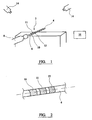
- Figure 1 shows a surgical instrument system which comprises a rotatable drill bit 2 having an elongate shaft.
- the shaft has a cutting portion 4 and a smooth surface portion 6.
- the drill bit is made from a surgical grade stainless steel.
- the diameter of the shaft is 6 mm in the illustrated embodiment, although it will be appreciated that the drill bit could have a size which is bigger than this or smaller than this.
- the system includes a drive unit 8 which the drill bit 2 fits into, and which causes the drill bit to rotate about the axis defined by the shaft.
- the smooth surface portion 6 of the shaft has first, second and third marker rings 10, 11, 12 on its surface.
- Each of the rings has a width (measured along the axis of the shaft) of 4 mm.
- the distance between adjacent edges of adjacent rings is 3 mm so that the centre to centre spacing of the rings is 7 mm.
- the rings on the surface of the shaft are provided by a curable polymeric material such as a epoxy material containing an appropriate pigment.
- the system includes two cameras 14, positioned with respect to the drive unit and cutting tool so that the rings on the shaft of the cutting tool are visible throughout use of the cutting tool in a surgical procedure.
- the pigment should be such that reflected light from the surface of the drill bit enables a sharp contrast to be observed between the rings and the regions of the shaft between the rings.
- the system includes a data processor 16 which can analyse the signals received from the cameras.
- the signals are analysed to determine the spacing between adjacent pairs of the rings, that is between the first and second rings, and between the second and third rings, as viewed by each camera. Determining the spacing involves (a) locating the axis of the shaft, which will generally extend along a line which is equidistant from the opposite edges (extending parallel to the shaft axis) of the rings, and (b) locating the centre line of each ring, which will intersect the axis of the shaft at a point which is equidistant from the opposite edges (extending perpendicular to the shaft axis) of the rings.
- the shaft of the tool is arranged so that it extends precisely perpendicular to a line which extends between the camera and the rings, the measured distances between the first and second rings, and between the second and third rings, respectively, will be the same. If the shaft of the tool is arranged so that the shaft is not exactly perpendicular to the line extending between the camera and the rings, the measured distances between the first and second rings, and between the second and third rings, respectively, will be different. For example when the third ring is further from the camera than the first ring, the measured distance between the first and second rings will be greater than the measured distance between the second and third rings.
- the orientation of the tool relative to the camera (which can be considered in terms of the angle between the shaft axis and the line extending between the camera and the rings) can be determined by simple trigonometry from knowledge of the apparent distances as determined from the receiving device and the actual distances as known from the registration of the tool.
Landscapes
- Health & Medical Sciences (AREA)
- Surgery (AREA)
- Life Sciences & Earth Sciences (AREA)
- Engineering & Computer Science (AREA)
- Medical Informatics (AREA)
- Molecular Biology (AREA)
- Veterinary Medicine (AREA)
- Public Health (AREA)
- Biomedical Technology (AREA)
- Heart & Thoracic Surgery (AREA)
- General Health & Medical Sciences (AREA)
- Nuclear Medicine, Radiotherapy & Molecular Imaging (AREA)
- Animal Behavior & Ethology (AREA)
- Oral & Maxillofacial Surgery (AREA)
- Pathology (AREA)
- Dentistry (AREA)
- Orthopedic Medicine & Surgery (AREA)
- Robotics (AREA)
- Surgical Instruments (AREA)
- Machine Tool Sensing Apparatuses (AREA)
Claims (9)
- Chirurgisches Instrumentensystem, das umfasst:a. ein Werkzeug (2) mit einem länglichen Schaft (4, 6), der die Schaftachse definiert, wobei der Schaft eine Vielzahl von Markierungsringen (10, 11, 12) trägt, die in einem vorab festgelegten Muster auf der Oberfläche des Schaftes so angeordnet sind, dass sie sich um die Schaftachse erstrecken,b. mindestens zwei Empfangseinrichtungen (14), die zum Empfangen von stereoskopischen Signalen von den Ringen an dem Werkzeug im Abstand zueinander angeordnet sind, undc. einen Datenprozessor (16) zur Analyse des Signals von den Ringen und Erzeugung von Information bezüglich der Position und Orientierung des Werkzeugs relativ zur Empfangseinrichtung,dadurch gekennzeichnet, dass das System eine Antriebseinheit (8) enthält, um dem Werkzeug eine Drehbewegung aufzuprägen, mit der sich das Werkzeug um die Schaftachse dreht.
- System nach Anspruch 1, wobei die Markierungsringe (10, 11, 12) stärker als die Oberfläche des Schaftes (4, 6), auf der sie angeordnet sind, reflektieren.
- System nach Anspruch 1, wobei mindestens drei Markierungsringe (10, 11, 12) vorhanden sind.
- System nach Anspruch 3, wobei die Distanz zwischen einem ersten Ring (10) und einem zweiten Ring (11), der sich benachbart zum ersten Ring befindet, dieselbe wie die Distanz zwischen besagtem zweiten Ring (11) und einem dritten Ring (12), der sich benachbart zum zweiten Ring auf der gegenüberliegende Seite des zweiten Ringes von dem ersten Ring befindet, ist.
- System nach Anspruch 1, wobei die von den axial im Abstand angeordneten Kanten jedes Ringes (10, 11, 12) definierten Ebenen parallel zueinander und senkrecht zur Achse des Schaftes (4, 6) verlaufen.
- System nach Anspruch 1, wobei die Ringe (10, 11, 12) auf einer Hülse markiert sind, die auf der Oberfläche des Werkzeugs (2) angebracht ist.
- System nach Anspruch 1, wobei das Werkzeug (2) ein Schneidwerkzeug ist.
- System nach Anspruch 1, wobei der Datenprozessor (16) programmiert ist, um die Schritte durchzuführen:a. Lokalisieren der Achse des Schaftes (4, 6), die sich allgemein entlang einer Linie erstrecken wird, die sich äquidistant von den gegenüberliegenden Kanten (, die sich parallel zur Schaftachse erstreckt), der Ringe (10, 11, 12) befindet, undb. Lokalisieren der Mittellinie jedes Ringes, die die Achse des Schaftes an einem Punkt schneiden wird, die sich äquidistant von den gegenüberliegenden Kanten (, die sich senkrecht zur Schaftachse erstrecken) des Ringes befindet.
- System nach Anspruch 1, wobei der Datenprozessor (16) programmiert ist, um die Schritte durchzuführen:a. Identifizieren von drei allgemein rechteckigen Gebieten, die die Ringe (10, 11, 12) an dem Schaft (4, 6) präsentieren, wenn der Schaft von einer Seite betrachtet wird,b. Ermitteln der Position einer Linie auf jedem der rechteckigen Gebiete, die den Mittelpunkt jedes Gebietes, gemessen parallel zur Achse des Werkzeuges (2), repräsentiert,c. Bestimmen des Winkels zwischen den Linien auf benachbarten der Rechtecke.
Applications Claiming Priority (3)
| Application Number | Priority Date | Filing Date | Title |
|---|---|---|---|
| GBGB0204549.0A GB0204549D0 (en) | 2002-02-27 | 2002-02-27 | A surgical instrument system |
| GB0204549 | 2002-02-27 | ||
| PCT/GB2003/000817 WO2003071968A1 (en) | 2002-02-27 | 2003-02-26 | A surgical instrument system |
Publications (2)
| Publication Number | Publication Date |
|---|---|
| EP1478296A1 EP1478296A1 (de) | 2004-11-24 |
| EP1478296B1 true EP1478296B1 (de) | 2011-12-28 |
Family
ID=9931855
Family Applications (2)
| Application Number | Title | Priority Date | Filing Date |
|---|---|---|---|
| EP03708325A Withdrawn EP1478297A1 (de) | 2002-02-27 | 2003-02-26 | Chirurgisches instrument und system |
| EP03708324A Expired - Lifetime EP1478296B1 (de) | 2002-02-27 | 2003-02-26 | Chirurgisches instrument und system |
Family Applications Before (1)
| Application Number | Title | Priority Date | Filing Date |
|---|---|---|---|
| EP03708325A Withdrawn EP1478297A1 (de) | 2002-02-27 | 2003-02-26 | Chirurgisches instrument und system |
Country Status (7)
| Country | Link |
|---|---|
| US (3) | US20050203544A1 (de) |
| EP (2) | EP1478297A1 (de) |
| JP (2) | JP2005518246A (de) |
| AT (1) | ATE538747T1 (de) |
| AU (2) | AU2003212506A1 (de) |
| GB (1) | GB0204549D0 (de) |
| WO (2) | WO2003071969A1 (de) |
Families Citing this family (29)
| Publication number | Priority date | Publication date | Assignee | Title |
|---|---|---|---|---|
| US7547307B2 (en) | 2001-02-27 | 2009-06-16 | Smith & Nephew, Inc. | Computer assisted knee arthroplasty instrumentation, systems, and processes |
| AU2003217389B2 (en) | 2002-02-11 | 2008-10-30 | Smith & Nephew, Inc. | Image-guided fracture reduction |
| WO2004091419A2 (en) | 2003-04-08 | 2004-10-28 | Wasielewski Ray C | Use of micro-and miniature position sensing devices for use in tka and tha |
| US7862570B2 (en) | 2003-10-03 | 2011-01-04 | Smith & Nephew, Inc. | Surgical positioners |
| US7764985B2 (en) | 2003-10-20 | 2010-07-27 | Smith & Nephew, Inc. | Surgical navigation system component fault interfaces and related processes |
| AU2004291146B2 (en) | 2003-11-14 | 2011-08-25 | Smith & Nephew, Inc. | Adjustable surgical cutting systems |
| JP2007531596A (ja) | 2004-03-31 | 2007-11-08 | スミス アンド ネフュー インコーポレーテッド | 基準アレイ入力装置を提供する方法及び装置 |
| EP1737375B1 (de) | 2004-04-21 | 2021-08-11 | Smith & Nephew, Inc | Computerunterstützte navigationssysteme für die schulter-arthroplastie |
| EP1816973A1 (de) * | 2004-12-02 | 2007-08-15 | Smith and Nephew, Inc. | Systeme, verfahren und vorrichtung für automatischen softwarefluss unter verwendung von instrumentenerkennung in der computergestützten chirurgie |
| AU2006214249B8 (en) | 2005-02-18 | 2011-11-17 | Komistek, Richard D | Smart joint implant sensors |
| WO2006091704A1 (en) | 2005-02-22 | 2006-08-31 | Smith & Nephew, Inc. | In-line milling system |
| EP1952779B1 (de) * | 2007-02-01 | 2012-04-04 | BrainLAB AG | Medizintechnische Instrumenten-Identifizierung |
| US9265589B2 (en) * | 2007-11-06 | 2016-02-23 | Medtronic Navigation, Inc. | System and method for navigated drill guide |
| WO2009089614A1 (en) * | 2008-01-14 | 2009-07-23 | The University Of Western Ontario | Sensorized medical instrument |
| DE102009014301A1 (de) * | 2008-03-28 | 2009-10-01 | Marquardt Gmbh | Bearbeitungsverfahren mit Elektrowerkzeug |
| US8029566B2 (en) * | 2008-06-02 | 2011-10-04 | Zimmer, Inc. | Implant sensors |
| US8852209B2 (en) | 2011-04-07 | 2014-10-07 | DePuy Synthes Products, LLC | Instrument adaptor for image guided surgery |
| WO2015003727A1 (en) | 2013-07-08 | 2015-01-15 | Brainlab Ag | Single-marker navigation |
| CN105228511A (zh) * | 2014-01-23 | 2016-01-06 | 奥林巴斯株式会社 | 外科用设备 |
| DE102014217095A1 (de) * | 2014-08-27 | 2016-03-03 | Olympus Winter & Ibe Gmbh | Elektrochirurgisches System und Verfahren zum Betreiben desselben |
| US20160278864A1 (en) * | 2015-03-19 | 2016-09-29 | Medtronic Navigation, Inc. | Apparatus And Method For Instrument And Gesture Based Image Guided Surgery |
| WO2017103046A2 (en) | 2015-12-18 | 2017-06-22 | Koninklijke Philips N.V. | Medical instrument tracking |
| EP3735929B1 (de) * | 2016-03-17 | 2024-06-19 | Brainlab AG | Optische verfolgung |
| US11197733B2 (en) | 2017-04-12 | 2021-12-14 | Mako Surgical Corp. | Packaging systems and methods for mounting a tool on a surgical device |
| KR20210031924A (ko) * | 2018-07-10 | 2021-03-23 | 인튜어티브 서지컬 오퍼레이션즈 인코포레이티드 | 의료 도구의 존재를 감지하기 위한 시스템 및 방법 |
| US11690680B2 (en) | 2019-03-19 | 2023-07-04 | Mako Surgical Corp. | Trackable protective packaging for tools and methods for calibrating tool installation using the same |
| US11395711B2 (en) | 2019-06-05 | 2022-07-26 | Stryker European Operations Limited | Packaging systems and methods for mounting a tool on a surgical device using the same |
| EP3944805A1 (de) * | 2020-07-30 | 2022-02-02 | Kreival Fast, S.L | Optisches system für chirurgische eingriffe und verfahren zur durchführung eines chirurgischen eingriffs mit bildvergrösserung |
| US20230329805A1 (en) * | 2022-04-15 | 2023-10-19 | Stryker Corporation | Pointer tool for endoscopic surgical procedures |
Family Cites Families (14)
| Publication number | Priority date | Publication date | Assignee | Title |
|---|---|---|---|---|
| CH664725A5 (de) | 1985-05-07 | 1988-03-31 | Synthes Ag | Zielvorrichtung mit einem in einem strahlenfeld zu betaetigendes werkzeug. |
| GB8920697D0 (en) | 1989-09-13 | 1989-10-25 | Isis Innovation | Apparatus and method for aligning drilling apparatus in surgical procedures |
| US5437280A (en) * | 1993-09-20 | 1995-08-01 | Hussman; Karl L. | Magnetic resonance breast localizer |
| US6246898B1 (en) * | 1995-03-28 | 2001-06-12 | Sonometrics Corporation | Method for carrying out a medical procedure using a three-dimensional tracking and imaging system |
| US5797849A (en) * | 1995-03-28 | 1998-08-25 | Sonometrics Corporation | Method for carrying out a medical procedure using a three-dimensional tracking and imaging system |
| CA2246341C (en) * | 1996-02-15 | 2007-05-01 | Biosense, Inc. | Precise position determination of endoscopes |
| US6272370B1 (en) * | 1998-08-07 | 2001-08-07 | The Regents Of University Of Minnesota | MR-visible medical device for neurological interventions using nonlinear magnetic stereotaxis and a method imaging |
| US6021343A (en) * | 1997-11-20 | 2000-02-01 | Surgical Navigation Technologies | Image guided awl/tap/screwdriver |
| US6332891B1 (en) * | 1999-02-16 | 2001-12-25 | Stryker Corporation | System and method for performing image guided surgery |
| DE69931074T2 (de) * | 1999-03-17 | 2006-11-16 | Synthes Ag Chur | Gerät zur darstellung und planung von kreuzbandersatzoperationen |
| US6317616B1 (en) * | 1999-09-15 | 2001-11-13 | Neil David Glossop | Method and system to facilitate image guided surgery |
| US6764452B1 (en) * | 1999-11-23 | 2004-07-20 | Nuvasive, Inc. | Bone graft harvester |
| US6725080B2 (en) * | 2000-03-01 | 2004-04-20 | Surgical Navigation Technologies, Inc. | Multiple cannula image guided tool for image guided procedures |
| US6478802B2 (en) * | 2000-06-09 | 2002-11-12 | Ge Medical Systems Global Technology Company, Llc | Method and apparatus for display of an image guided drill bit |
-
2002
- 2002-02-27 GB GBGB0204549.0A patent/GB0204549D0/en not_active Ceased
-
2003
- 2003-02-26 EP EP03708325A patent/EP1478297A1/de not_active Withdrawn
- 2003-02-26 JP JP2003570717A patent/JP2005518246A/ja active Pending
- 2003-02-26 JP JP2003570716A patent/JP4387200B2/ja not_active Expired - Lifetime
- 2003-02-26 AU AU2003212506A patent/AU2003212506A1/en not_active Abandoned
- 2003-02-26 EP EP03708324A patent/EP1478296B1/de not_active Expired - Lifetime
- 2003-02-26 AU AU2003212505A patent/AU2003212505A1/en not_active Abandoned
- 2003-02-26 US US10/505,266 patent/US20050203544A1/en not_active Abandoned
- 2003-02-26 WO PCT/GB2003/000822 patent/WO2003071969A1/en not_active Ceased
- 2003-02-26 US US10/505,304 patent/US20050251186A1/en not_active Abandoned
- 2003-02-26 AT AT03708324T patent/ATE538747T1/de active
- 2003-02-26 WO PCT/GB2003/000817 patent/WO2003071968A1/en not_active Ceased
-
2010
- 2010-09-27 US US12/891,259 patent/US9775626B2/en not_active Expired - Fee Related
Also Published As
| Publication number | Publication date |
|---|---|
| GB0204549D0 (en) | 2002-04-10 |
| WO2003071968A1 (en) | 2003-09-04 |
| JP4387200B2 (ja) | 2009-12-16 |
| US20050203544A1 (en) | 2005-09-15 |
| JP2005518245A (ja) | 2005-06-23 |
| US20050251186A1 (en) | 2005-11-10 |
| WO2003071969A1 (en) | 2003-09-04 |
| AU2003212505A1 (en) | 2003-09-09 |
| JP2005518246A (ja) | 2005-06-23 |
| AU2003212506A1 (en) | 2003-09-09 |
| EP1478297A1 (de) | 2004-11-24 |
| EP1478296A1 (de) | 2004-11-24 |
| ATE538747T1 (de) | 2012-01-15 |
| US20110082460A1 (en) | 2011-04-07 |
| US9775626B2 (en) | 2017-10-03 |
Similar Documents
| Publication | Publication Date | Title |
|---|---|---|
| US9775626B2 (en) | Method of cutting for use in surgery | |
| JP5146692B2 (ja) | 光学的位置測定ならびに剛性または半可撓性の針の標的への誘導のためのシステム | |
| US7670345B2 (en) | User guidance in adjusting bone incision blocks | |
| US6478802B2 (en) | Method and apparatus for display of an image guided drill bit | |
| US20020193800A1 (en) | Surgical drill for use with a computer assisted surgery system | |
| EP3381414B1 (de) | Positionierungssystem für knochenresektionsinstrumente und positionierungs-kit | |
| US20090247861A1 (en) | Calibration method for axially determinate medical instruments | |
| US20080185430A1 (en) | Medical instrument identification | |
| CA2333981A1 (en) | Infrared surgical site locating device and method | |
| EP3556312B1 (de) | Ein dreidimensionales visionsystem | |
| EP3001219A1 (de) | Optische Verfolgung | |
| CN106943173A (zh) | 旋转式鼻窦成形术切割器的光学配准 | |
| US20160346046A1 (en) | Identification and calibration method | |
| CN114366299B (zh) | 用于确定器械的末端的球形表面部分的半径的技术 | |
| US12207889B2 (en) | Endoscope with procedure guidance | |
| US11963725B2 (en) | Surgical tool position tracking and scoring system | |
| CN209107577U (zh) | 标定装置 | |
| CN103735314B (zh) | 用于显示位置标记的位置的医疗器械、医学系统和方法 | |
| JP2005189023A (ja) | X線計測装置及びそれに用いる検体識別具 | |
| JP7739471B2 (ja) | コンピュータ支援手術casのための手術ガイドシステム | |
| CN121443241A (zh) | 校准装置、校准系统和校准方法 | |
| WO2016156879A1 (en) | Method and apparatus for improved control of drilling and the like apparatus | |
| WO2022125715A1 (en) | Needle guidance system | |
| WO2024125772A1 (en) | Simultaneous multi-view live targeting leveraging patient-mounted reference bodies | |
| CN120769732A (zh) | 在计算机辅助外科手术中使用的装置 |
Legal Events
| Date | Code | Title | Description |
|---|---|---|---|
| PUAI | Public reference made under article 153(3) epc to a published international application that has entered the european phase |
Free format text: ORIGINAL CODE: 0009012 |
|
| 17P | Request for examination filed |
Effective date: 20040722 |
|
| AK | Designated contracting states |
Kind code of ref document: A1 Designated state(s): AT BE BG CH CY CZ DE DK EE ES FI FR GB GR HU IE IT LI LU MC NL PT SE SI SK TR |
|
| AX | Request for extension of the european patent |
Extension state: AL LT LV MK RO |
|
| 17Q | First examination report despatched |
Effective date: 20090730 |
|
| GRAP | Despatch of communication of intention to grant a patent |
Free format text: ORIGINAL CODE: EPIDOSNIGR1 |
|
| GRAS | Grant fee paid |
Free format text: ORIGINAL CODE: EPIDOSNIGR3 |
|
| GRAA | (expected) grant |
Free format text: ORIGINAL CODE: 0009210 |
|
| AK | Designated contracting states |
Kind code of ref document: B1 Designated state(s): AT BE BG CH CY CZ DE DK EE ES FI FR GB GR HU IE IT LI LU MC NL PT SE SI SK TR |
|
| REG | Reference to a national code |
Ref country code: GB Ref legal event code: FG4D |
|
| REG | Reference to a national code |
Ref country code: CH Ref legal event code: EP |
|
| REG | Reference to a national code |
Ref country code: CH Ref legal event code: NV Representative=s name: E. BLUM & CO. AG PATENT- UND MARKENANWAELTE VSP |
|
| REG | Reference to a national code |
Ref country code: AT Ref legal event code: REF Ref document number: 538747 Country of ref document: AT Kind code of ref document: T Effective date: 20120115 |
|
| REG | Reference to a national code |
Ref country code: IE Ref legal event code: FG4D |
|
| REG | Reference to a national code |
Ref country code: DE Ref legal event code: R096 Ref document number: 60339536 Country of ref document: DE Effective date: 20120308 |
|
| REG | Reference to a national code |
Ref country code: NL Ref legal event code: VDEP Effective date: 20111228 |
|
| PG25 | Lapsed in a contracting state [announced via postgrant information from national office to epo] |
Ref country code: SE Free format text: LAPSE BECAUSE OF FAILURE TO SUBMIT A TRANSLATION OF THE DESCRIPTION OR TO PAY THE FEE WITHIN THE PRESCRIBED TIME-LIMIT Effective date: 20111228 Ref country code: GR Free format text: LAPSE BECAUSE OF FAILURE TO SUBMIT A TRANSLATION OF THE DESCRIPTION OR TO PAY THE FEE WITHIN THE PRESCRIBED TIME-LIMIT Effective date: 20120329 Ref country code: SI Free format text: LAPSE BECAUSE OF FAILURE TO SUBMIT A TRANSLATION OF THE DESCRIPTION OR TO PAY THE FEE WITHIN THE PRESCRIBED TIME-LIMIT Effective date: 20111228 |
|
| PG25 | Lapsed in a contracting state [announced via postgrant information from national office to epo] |
Ref country code: CY Free format text: LAPSE BECAUSE OF FAILURE TO SUBMIT A TRANSLATION OF THE DESCRIPTION OR TO PAY THE FEE WITHIN THE PRESCRIBED TIME-LIMIT Effective date: 20111228 Ref country code: BE Free format text: LAPSE BECAUSE OF FAILURE TO SUBMIT A TRANSLATION OF THE DESCRIPTION OR TO PAY THE FEE WITHIN THE PRESCRIBED TIME-LIMIT Effective date: 20111228 |
|
| PG25 | Lapsed in a contracting state [announced via postgrant information from national office to epo] |
Ref country code: CZ Free format text: LAPSE BECAUSE OF FAILURE TO SUBMIT A TRANSLATION OF THE DESCRIPTION OR TO PAY THE FEE WITHIN THE PRESCRIBED TIME-LIMIT Effective date: 20111228 Ref country code: SK Free format text: LAPSE BECAUSE OF FAILURE TO SUBMIT A TRANSLATION OF THE DESCRIPTION OR TO PAY THE FEE WITHIN THE PRESCRIBED TIME-LIMIT Effective date: 20111228 Ref country code: NL Free format text: LAPSE BECAUSE OF FAILURE TO SUBMIT A TRANSLATION OF THE DESCRIPTION OR TO PAY THE FEE WITHIN THE PRESCRIBED TIME-LIMIT Effective date: 20111228 Ref country code: BG Free format text: LAPSE BECAUSE OF FAILURE TO SUBMIT A TRANSLATION OF THE DESCRIPTION OR TO PAY THE FEE WITHIN THE PRESCRIBED TIME-LIMIT Effective date: 20120328 Ref country code: EE Free format text: LAPSE BECAUSE OF FAILURE TO SUBMIT A TRANSLATION OF THE DESCRIPTION OR TO PAY THE FEE WITHIN THE PRESCRIBED TIME-LIMIT Effective date: 20111228 |
|
| PG25 | Lapsed in a contracting state [announced via postgrant information from national office to epo] |
Ref country code: PT Free format text: LAPSE BECAUSE OF FAILURE TO SUBMIT A TRANSLATION OF THE DESCRIPTION OR TO PAY THE FEE WITHIN THE PRESCRIBED TIME-LIMIT Effective date: 20120430 |
|
| REG | Reference to a national code |
Ref country code: AT Ref legal event code: MK05 Ref document number: 538747 Country of ref document: AT Kind code of ref document: T Effective date: 20111228 |
|
| PG25 | Lapsed in a contracting state [announced via postgrant information from national office to epo] |
Ref country code: MC Free format text: LAPSE BECAUSE OF NON-PAYMENT OF DUE FEES Effective date: 20120229 |
|
| PG25 | Lapsed in a contracting state [announced via postgrant information from national office to epo] |
Ref country code: DK Free format text: LAPSE BECAUSE OF FAILURE TO SUBMIT A TRANSLATION OF THE DESCRIPTION OR TO PAY THE FEE WITHIN THE PRESCRIBED TIME-LIMIT Effective date: 20111228 |
|
| PLBE | No opposition filed within time limit |
Free format text: ORIGINAL CODE: 0009261 |
|
| STAA | Information on the status of an ep patent application or granted ep patent |
Free format text: STATUS: NO OPPOSITION FILED WITHIN TIME LIMIT |
|
| PG25 | Lapsed in a contracting state [announced via postgrant information from national office to epo] |
Ref country code: IT Free format text: LAPSE BECAUSE OF FAILURE TO SUBMIT A TRANSLATION OF THE DESCRIPTION OR TO PAY THE FEE WITHIN THE PRESCRIBED TIME-LIMIT Effective date: 20111228 |
|
| 26N | No opposition filed |
Effective date: 20121001 |
|
| REG | Reference to a national code |
Ref country code: DE Ref legal event code: R097 Ref document number: 60339536 Country of ref document: DE Effective date: 20121001 |
|
| PG25 | Lapsed in a contracting state [announced via postgrant information from national office to epo] |
Ref country code: AT Free format text: LAPSE BECAUSE OF FAILURE TO SUBMIT A TRANSLATION OF THE DESCRIPTION OR TO PAY THE FEE WITHIN THE PRESCRIBED TIME-LIMIT Effective date: 20111228 |
|
| PG25 | Lapsed in a contracting state [announced via postgrant information from national office to epo] |
Ref country code: ES Free format text: LAPSE BECAUSE OF FAILURE TO SUBMIT A TRANSLATION OF THE DESCRIPTION OR TO PAY THE FEE WITHIN THE PRESCRIBED TIME-LIMIT Effective date: 20120408 |
|
| PG25 | Lapsed in a contracting state [announced via postgrant information from national office to epo] |
Ref country code: FI Free format text: LAPSE BECAUSE OF FAILURE TO SUBMIT A TRANSLATION OF THE DESCRIPTION OR TO PAY THE FEE WITHIN THE PRESCRIBED TIME-LIMIT Effective date: 20111228 |
|
| PG25 | Lapsed in a contracting state [announced via postgrant information from national office to epo] |
Ref country code: TR Free format text: LAPSE BECAUSE OF FAILURE TO SUBMIT A TRANSLATION OF THE DESCRIPTION OR TO PAY THE FEE WITHIN THE PRESCRIBED TIME-LIMIT Effective date: 20111228 |
|
| PG25 | Lapsed in a contracting state [announced via postgrant information from national office to epo] |
Ref country code: LU Free format text: LAPSE BECAUSE OF NON-PAYMENT OF DUE FEES Effective date: 20120226 |
|
| PG25 | Lapsed in a contracting state [announced via postgrant information from national office to epo] |
Ref country code: HU Free format text: LAPSE BECAUSE OF FAILURE TO SUBMIT A TRANSLATION OF THE DESCRIPTION OR TO PAY THE FEE WITHIN THE PRESCRIBED TIME-LIMIT Effective date: 20030226 |
|
| REG | Reference to a national code |
Ref country code: FR Ref legal event code: PLFP Year of fee payment: 14 |
|
| REG | Reference to a national code |
Ref country code: FR Ref legal event code: PLFP Year of fee payment: 15 |
|
| REG | Reference to a national code |
Ref country code: FR Ref legal event code: PLFP Year of fee payment: 16 |
|
| PGFP | Annual fee paid to national office [announced via postgrant information from national office to epo] |
Ref country code: IE Payment date: 20220110 Year of fee payment: 20 Ref country code: GB Payment date: 20220106 Year of fee payment: 20 Ref country code: DE Payment date: 20220105 Year of fee payment: 20 Ref country code: CH Payment date: 20220114 Year of fee payment: 20 |
|
| PGFP | Annual fee paid to national office [announced via postgrant information from national office to epo] |
Ref country code: FR Payment date: 20220118 Year of fee payment: 20 |
|
| REG | Reference to a national code |
Ref country code: DE Ref legal event code: R071 Ref document number: 60339536 Country of ref document: DE |
|
| REG | Reference to a national code |
Ref country code: CH Ref legal event code: PL |
|
| REG | Reference to a national code |
Ref country code: GB Ref legal event code: PE20 Expiry date: 20230225 |
|
| REG | Reference to a national code |
Ref country code: IE Ref legal event code: MK9A |
|
| PG25 | Lapsed in a contracting state [announced via postgrant information from national office to epo] |
Ref country code: IE Free format text: LAPSE BECAUSE OF EXPIRATION OF PROTECTION Effective date: 20230226 |
|
| PG25 | Lapsed in a contracting state [announced via postgrant information from national office to epo] |
Ref country code: GB Free format text: LAPSE BECAUSE OF EXPIRATION OF PROTECTION Effective date: 20230225 |