EP1477976A1 - Optical disk of intergroove recording system - Google Patents
Optical disk of intergroove recording system Download PDFInfo
- Publication number
- EP1477976A1 EP1477976A1 EP02788818A EP02788818A EP1477976A1 EP 1477976 A1 EP1477976 A1 EP 1477976A1 EP 02788818 A EP02788818 A EP 02788818A EP 02788818 A EP02788818 A EP 02788818A EP 1477976 A1 EP1477976 A1 EP 1477976A1
- Authority
- EP
- European Patent Office
- Prior art keywords
- layer
- optical
- characteristic
- changeable
- reflection
- Prior art date
- Legal status (The legal status is an assumption and is not a legal conclusion. Google has not performed a legal analysis and makes no representation as to the accuracy of the status listed.)
- Withdrawn
Links
Images


Classifications
-
- G—PHYSICS
- G11—INFORMATION STORAGE
- G11B—INFORMATION STORAGE BASED ON RELATIVE MOVEMENT BETWEEN RECORD CARRIER AND TRANSDUCER
- G11B7/00—Recording or reproducing by optical means, e.g. recording using a thermal beam of optical radiation by modifying optical properties or the physical structure, reproducing using an optical beam at lower power by sensing optical properties; Record carriers therefor
- G11B7/24—Record carriers characterised by shape, structure or physical properties, or by the selection of the material
- G11B7/241—Record carriers characterised by shape, structure or physical properties, or by the selection of the material characterised by the selection of the material
- G11B7/252—Record carriers characterised by shape, structure or physical properties, or by the selection of the material characterised by the selection of the material of layers other than recording layers
- G11B7/254—Record carriers characterised by shape, structure or physical properties, or by the selection of the material characterised by the selection of the material of layers other than recording layers of protective topcoat layers
- G11B7/2542—Record carriers characterised by shape, structure or physical properties, or by the selection of the material characterised by the selection of the material of layers other than recording layers of protective topcoat layers consisting essentially of organic resins
-
- G—PHYSICS
- G11—INFORMATION STORAGE
- G11B—INFORMATION STORAGE BASED ON RELATIVE MOVEMENT BETWEEN RECORD CARRIER AND TRANSDUCER
- G11B7/00—Recording or reproducing by optical means, e.g. recording using a thermal beam of optical radiation by modifying optical properties or the physical structure, reproducing using an optical beam at lower power by sensing optical properties; Record carriers therefor
- G11B7/24—Record carriers characterised by shape, structure or physical properties, or by the selection of the material
-
- G—PHYSICS
- G11—INFORMATION STORAGE
- G11B—INFORMATION STORAGE BASED ON RELATIVE MOVEMENT BETWEEN RECORD CARRIER AND TRANSDUCER
- G11B7/00—Recording or reproducing by optical means, e.g. recording using a thermal beam of optical radiation by modifying optical properties or the physical structure, reproducing using an optical beam at lower power by sensing optical properties; Record carriers therefor
- G11B7/24—Record carriers characterised by shape, structure or physical properties, or by the selection of the material
- G11B7/241—Record carriers characterised by shape, structure or physical properties, or by the selection of the material characterised by the selection of the material
- G11B7/252—Record carriers characterised by shape, structure or physical properties, or by the selection of the material characterised by the selection of the material of layers other than recording layers
- G11B7/257—Record carriers characterised by shape, structure or physical properties, or by the selection of the material characterised by the selection of the material of layers other than recording layers of layers having properties involved in recording or reproduction, e.g. optical interference layers or sensitising layers or dielectric layers, which are protecting the recording layers
- G11B2007/25705—Record carriers characterised by shape, structure or physical properties, or by the selection of the material characterised by the selection of the material of layers other than recording layers of layers having properties involved in recording or reproduction, e.g. optical interference layers or sensitising layers or dielectric layers, which are protecting the recording layers consisting essentially of inorganic materials
- G11B2007/25708—Record carriers characterised by shape, structure or physical properties, or by the selection of the material characterised by the selection of the material of layers other than recording layers of layers having properties involved in recording or reproduction, e.g. optical interference layers or sensitising layers or dielectric layers, which are protecting the recording layers consisting essentially of inorganic materials containing group 13 elements (B, Al, Ga)
-
- G—PHYSICS
- G11—INFORMATION STORAGE
- G11B—INFORMATION STORAGE BASED ON RELATIVE MOVEMENT BETWEEN RECORD CARRIER AND TRANSDUCER
- G11B7/00—Recording or reproducing by optical means, e.g. recording using a thermal beam of optical radiation by modifying optical properties or the physical structure, reproducing using an optical beam at lower power by sensing optical properties; Record carriers therefor
- G11B7/24—Record carriers characterised by shape, structure or physical properties, or by the selection of the material
- G11B7/241—Record carriers characterised by shape, structure or physical properties, or by the selection of the material characterised by the selection of the material
- G11B7/252—Record carriers characterised by shape, structure or physical properties, or by the selection of the material characterised by the selection of the material of layers other than recording layers
- G11B7/257—Record carriers characterised by shape, structure or physical properties, or by the selection of the material characterised by the selection of the material of layers other than recording layers of layers having properties involved in recording or reproduction, e.g. optical interference layers or sensitising layers or dielectric layers, which are protecting the recording layers
- G11B2007/25705—Record carriers characterised by shape, structure or physical properties, or by the selection of the material characterised by the selection of the material of layers other than recording layers of layers having properties involved in recording or reproduction, e.g. optical interference layers or sensitising layers or dielectric layers, which are protecting the recording layers consisting essentially of inorganic materials
- G11B2007/25713—Record carriers characterised by shape, structure or physical properties, or by the selection of the material characterised by the selection of the material of layers other than recording layers of layers having properties involved in recording or reproduction, e.g. optical interference layers or sensitising layers or dielectric layers, which are protecting the recording layers consisting essentially of inorganic materials containing nitrogen
-
- G—PHYSICS
- G11—INFORMATION STORAGE
- G11B—INFORMATION STORAGE BASED ON RELATIVE MOVEMENT BETWEEN RECORD CARRIER AND TRANSDUCER
- G11B7/00—Recording or reproducing by optical means, e.g. recording using a thermal beam of optical radiation by modifying optical properties or the physical structure, reproducing using an optical beam at lower power by sensing optical properties; Record carriers therefor
- G11B7/004—Recording, reproducing or erasing methods; Read, write or erase circuits therefor
- G11B7/0045—Recording
- G11B7/00455—Recording involving reflectivity, absorption or colour changes
-
- G—PHYSICS
- G11—INFORMATION STORAGE
- G11B—INFORMATION STORAGE BASED ON RELATIVE MOVEMENT BETWEEN RECORD CARRIER AND TRANSDUCER
- G11B7/00—Recording or reproducing by optical means, e.g. recording using a thermal beam of optical radiation by modifying optical properties or the physical structure, reproducing using an optical beam at lower power by sensing optical properties; Record carriers therefor
- G11B7/24—Record carriers characterised by shape, structure or physical properties, or by the selection of the material
- G11B7/241—Record carriers characterised by shape, structure or physical properties, or by the selection of the material characterised by the selection of the material
- G11B7/242—Record carriers characterised by shape, structure or physical properties, or by the selection of the material characterised by the selection of the material of recording layers
- G11B7/244—Record carriers characterised by shape, structure or physical properties, or by the selection of the material characterised by the selection of the material of recording layers comprising organic materials only
- G11B7/246—Record carriers characterised by shape, structure or physical properties, or by the selection of the material characterised by the selection of the material of recording layers comprising organic materials only containing dyes
-
- G—PHYSICS
- G11—INFORMATION STORAGE
- G11B—INFORMATION STORAGE BASED ON RELATIVE MOVEMENT BETWEEN RECORD CARRIER AND TRANSDUCER
- G11B7/00—Recording or reproducing by optical means, e.g. recording using a thermal beam of optical radiation by modifying optical properties or the physical structure, reproducing using an optical beam at lower power by sensing optical properties; Record carriers therefor
- G11B7/24—Record carriers characterised by shape, structure or physical properties, or by the selection of the material
- G11B7/241—Record carriers characterised by shape, structure or physical properties, or by the selection of the material characterised by the selection of the material
- G11B7/252—Record carriers characterised by shape, structure or physical properties, or by the selection of the material characterised by the selection of the material of layers other than recording layers
- G11B7/253—Record carriers characterised by shape, structure or physical properties, or by the selection of the material characterised by the selection of the material of layers other than recording layers of substrates
- G11B7/2533—Record carriers characterised by shape, structure or physical properties, or by the selection of the material characterised by the selection of the material of layers other than recording layers of substrates comprising resins
- G11B7/2534—Record carriers characterised by shape, structure or physical properties, or by the selection of the material characterised by the selection of the material of layers other than recording layers of substrates comprising resins polycarbonates [PC]
-
- G—PHYSICS
- G11—INFORMATION STORAGE
- G11B—INFORMATION STORAGE BASED ON RELATIVE MOVEMENT BETWEEN RECORD CARRIER AND TRANSDUCER
- G11B7/00—Recording or reproducing by optical means, e.g. recording using a thermal beam of optical radiation by modifying optical properties or the physical structure, reproducing using an optical beam at lower power by sensing optical properties; Record carriers therefor
- G11B7/24—Record carriers characterised by shape, structure or physical properties, or by the selection of the material
- G11B7/241—Record carriers characterised by shape, structure or physical properties, or by the selection of the material characterised by the selection of the material
- G11B7/252—Record carriers characterised by shape, structure or physical properties, or by the selection of the material characterised by the selection of the material of layers other than recording layers
- G11B7/258—Record carriers characterised by shape, structure or physical properties, or by the selection of the material characterised by the selection of the material of layers other than recording layers of reflective layers
- G11B7/2585—Record carriers characterised by shape, structure or physical properties, or by the selection of the material characterised by the selection of the material of layers other than recording layers of reflective layers based on aluminium
Definitions
- the present invention relates to a write once type optical disc.
- conventional write once optical discs such as CD-R (recordable) and DVD-R
- a transparent, resin substrate has guide grooves on one surface of the substrate.
- an organic dye is applied by spin coating.
- a metallic reflection layer made from for example gold, silver (or silver alloy) and aluminum (or aluminum alloy) is formed on the organic dye layer.
- a protection layer such as an ultraviolet ray curing resin (referred to as "cover layer") is applied on the metallic reflection layer.
- a laser beam for information recording is radiated on the substrate side. The laser beam decomposes the organic dye so that a refractive index changes. Heat generated by the laser beam also deforms the guide grooves and the reflection layer. As a result, pits are formed on the optical disc as recorded information.
- DVR digital Video Recorder
- a violet laser is utilized as a light source for information recordation and retrieval, and an object lens having a high numerical aperture such as 0.85 or more is employed.
- a cover layer of the DVR has a thickness of about 0.1mm, and the laser beam is radiated on the cover layer side. This suppresses an influence of optical aberration caused when the object lens having a high numerical aperture is used. This in turn increases a recording density so that a large quantity of information can be recorded on the optical disc.
- a write once optical disc utilizing the DVR system is referred to as "DVR-R disc".
- the direction of the laser beam radiation for the DVR-R disc is different from that for the conventional write once optical disc such as CD-R disc and DVD-R disc.
- the accumulating direction of the layers formed on the resin substrate of the DVR-R disc is opposite that of the CD-R and DVD-R. This is called a "reverse stack" structure.
- the DVR-R disc needs a dielectric protection layer to protect the organic dye layer from a non-cured ultraviolet curing resin during formation of the cover layer.
- the ultraviolet curing resin is used to form the cover layer.
- the structure and manufacturing method of the DVR-R disc are different from the conventional optical disc.
- the DVR-R disc should be manufactured with materials and structure that are particularly suited for the DVR-R disc.
- An object of the present invention is to provide a DVR-R disc which can have smaller recordation marks (indicia) to achieve large quantity recordation.
- an optical disc comprising: a resin substrate having grooves on a surface thereof; a reflection layer formed over the surface of the resin substrate such that the reflection layer has a shape corresponding to the grooves; a characteristic-changeable layer formed over the reflection layer, the characteristic-changeable layer having an optical characteristic which varies when a light beam is radiated; a light-transmissive protection layer formed over the optical-characteristic-changeable layer; and a light-transmissive cover layer formed over the protection layer for sealing the reflection layer, optical-characteristic-changeable layer and protection layer to the resin substrate, wherein hardness of the resin substrate is greater than hardness of the cover layer, at least after the optical characteristic of the optical-characteristic-changeable layer changes upon radiation of a light beam to convex portions of the optical-characteristic-changeable layer between the grooves.
- the optical-characteristic-changeable layer deforms when the light beam is radiated to the optical-characteristic-changeable layer. Since the substrate is harder than the protection layer, the substrate deforms less than the protection layer when the optical-characteristic-changeable layer deforms. It is therefore possible to record finer information on the optical disc and achieve a high-density intergroove-recording type optical disc.
- the optical disc may be configured such that heat is transferred toward the protection layer from the optical-characteristic-changeable layer in a greater amount than toward the reflection layer.
- An optical disc 8 includes a resin substrate 10, which is made from a macromolecular material such as polycarbonate and polyolefin.
- a plurality of grooves 12 are formed on a recordation surface of the substrate 10. The grooves define information tracks between the grooves.
- the grooves 12 wobble to define addresses (or to provide address information) of data recorded on the disc.
- projections between the grooves 12 i.e., lands 16
- information is recorded on a recording layer formed on the lands 16.
- This recordation scheme is called "on-groove recordation” or “intergroove recordation”.
- a reflection layer 13 is formed over the groove surface of the substrate 10.
- a material of the reflection layer 13 is, for example, aluminum, aluminum alloy, silver or silver alloy, and the reflection layer 13 can be made thin with high reflectance.
- An organic dye layer 14 is applied over the reflection layer 13.
- the organic layer 14 is made by, for example, spin-coating an organic dye. Because the on-groove recordation scheme is employed in this embodiment, the organic dye layer 14 has to have a sufficient thickness over the lands 16 between the grooves 12, as shown in Figure 1C.
- a ratio of the organic dye layer thickness in the groove to the organic dye layer thickness on the land 16 is between approximately 2:1 and 3:2. If the organic dye layer has to have a thickness of 30nm to ensure sufficient recording of information, then the organic dye layer thickness on the land 16 is 30nm and the organic dye layer thickness in the groove is approximately 45-60nm. If the groove depth is 40nm, therefore, the groove of the substrate is entirely filled with the organic dye. Further, since the organic dye layer in the groove projects from the groove by 5-20nm, the organic dye layer in the groove is continuous to the organic dye layer on an adjacent land 16 by the 5-20nm thickness.
- a protection layer 15 is formed over the organic dye layer 14.
- the protection layer 15 protects the organic dye layer 14 from an ultraviolet curing resin of a cover layer 11.
- the protection layer 15 is made from a metallic oxide such as SiOx and AlOx or a metallic nitride such as SiNx and AlNx because the protection layer 15 should protect the organic dye layer and be highly transparent.
- the cover layer 11 is formed on the protection layer 15.
- the cover layer 11 is made from, for example, a macromolecular resin such as polycarbonate.
- the cover layer 11 is transparent since the laser beam for information recordation passes through the cover layer 11.
- hardness is an indentation hardness.
- the “hardness” is Brinell hardness (JIS-Z2243), Vickers hardness (JIS-Z2244), Rockwell hardness (JIS-Z2245) or pencil hardness (JIS-K5400), or combination thereof.
- JIS-Z2243 Brinell hardness
- Vickers hardness JIS-Z2244
- Rockwell hardness JIS-Z2245
- pencil hardness JIS-K5400
- conditional equation for the "hardness" of the optical disc layers is not limited to the above described equation in this embodiment.
- a refractive index of the organic dye layer changes with a temperature which elevates as the laser beam is radiated for information recordation.
- the refractive index of the organic dye layer changes (i.e., when the temperature of the organic dye layer is lower than a certain temperature T which causes a significant non-linear volumetric expansion in the organic dye layer, such as the pyrolysis temperature of the dye, the melting temperature of the dye and the sublimation temperature of the dye), the following equation may be established in this embodiment: Ha ⁇ Hb
- the refractive index changes i.e., when the temperature of the organic dye layer exceeds the temperature T, however, the following relationship may be established: Ha > Hb
- the indentation hardness test a surface layer (up to several tens nm from the surface) of the test material can be ignored. In this embodiment, therefore, the reflection layer 13 (approximately 20nm in thickness) formed on the substrate 10 and the protection layer 15 (approximately 50nm in thickness) formed on the cover layer 11 can be ignored. Accordingly, it can be assumed that the hardness Ha represents the hardness of the substrate itself and the hardness Hb represents the hardness of the cover layer itself.
- a master disc which has the same grooves as those to be formed on the substrate was prepared by an electron-beam recorder and electron resist.
- a nickel stamper was then created from the master disc by electroforming.
- a resin substrate 10 was formed from the nickel stamper by injection molding.
- a material of the resin substrate 10 was polycarbonate.
- the substrate 10 was about 120 mm in diameter, about 1.1mm in thickness, about 40nm in groove depth, 320nm in track pitch, and 130nm in land width.
- the land width is equal to an interval between adjacent grooves 12. Lateral walls of the groove 12 had about 90-degree inclination.
- a reflection layer 13 was formed over the grooves 12 of the substrate 10.
- the reflection layer 13 having a thickness of about 20nm was fabricated by sputtering.
- the protection layer 15 was made from aluminum nitride (AlNx).
- AlNx aluminum nitride
- the aluminum nitride was prepared by reactive sputtering, with aluminum being used as a target and Ar-N2 (10:1) used as a reactive gas.
- the cover layer 11 was a polycarbonate film having an approximately 0.095mm thickness, and fixed by an ultraviolet curing adhesive.
- the DVR-R disc fabricated in this manner underwent a pencil hardness test. The test showed that the substrate hardness was HB and the cover layer hardness was 2B.
- the laser beam is radiated to the cover layer 11 of the optical disc 8 when recording information on the optical disc 8 in this embodiment.
- the laser beam is transmitted through the cover layer 11 and protection layer 15 and converges on the organic dye layer 14 between the grooves 12 (or on the land), thereby forming a beam spot 20 on the land.
- the laser beam causes the thermal decomposition of the organic dye so that the refractive index of the organic dye changes. This change of the refractive index is irreversible. Therefore, the changed refractive index does not return to the original refractive index after the laser beam radiation is finished and the temperature of the organic dye layer drops to room temperature. This is a principle of information recording on the organic dye layer 14 at the land portion 16.
- the volume of the organic dye increases and generates a stress in the organic dye layer 14 in and around the laser beam spot. Therefore, if the substrate 10 is softer than the cover layer 11, deformations caused by the stress disperse to the reflection layer 13 and substrate 10, as indicated by the phantom lines shown in Figure 2A. The deformation of the reflection layer 13 adversely influences the information recorded on the tracks when retrieving the recorded information.
- the DVR-R disc 8 When the information is retrieved from the DVR-R disc 8, reflection of the laser beam from the reflection layer 13 is utilized. Therefore, if the reflection layer 13 has deformed, a retrieved signal includes a large distortion. Particularly, the DVR-R disc has a very small track pitch to increase a recording density, as compared with a general DVD-R. Spacing between marks, which are created on the disc when the information is recorded by the laser beam spot 20, is also small. Therefore, the deformed reflection layer is likely to affect the retrieved signal and cause crosstalk or interference between adjacent tracks.
- the resin substrate 10 is always harder than the cover layer 11, or the resin substrate 10 is harder than the cover layer 11 when the refractive index of the organic dye layer changes upon laser beam radiation.
- the stress generated due to volumetric expansion of the organic dye layer 14 disperses to the cover layer 11, as indicated by the phantom lines in Figure 2B.
- the refractive index of the organic dye layer 14 can be set to be very close to the refractive index of the cover layer 11 (and that of the protection layer 15) because of characteristics of the materials.
- the refractive index difference may be about 0.1-1.0.
- the cover layer 11 and protection layer 15 deform due to the stress, as shown in Figure 2B, reflection from an interface between the cover layer and the protection layer is neglectable.
- the cover layer and protection layer are both transparent so that the deformed cover layer and deformed protection layer do not deteriorate the information retrieval quality.
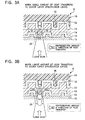
- FIG. 3B A second embodiment of the present invention will be described with reference to the cross sectional view of the disc shown in Figure 3B.
- the manufacturing method and structure of the DVR-R disc 8 of this embodiment are similar to those of the first embodiment so that a description therefor is omitted.
- Figures 1A to 1C are also referred to in this embodiment when the structure of the optical disc 8 is described. Similar reference numerals and symbols are used to designate similar elements in Figures 1A, 1B, 1C, 3A and 3B.
- the second embodiment is particularly directed to an optical disc which includes optimal materials for preventing occurrence of crosswrite.
- Crosswrite is a phenomenon in which the heat of the organic dye generated by the laser beam radiated during information recordation interferes with adjacent information recording tracks.
- the optical disc 8 of the second embodiment records information on an organic dye layer 14 at lands 16 between grooves 12.
- the laser beam creates a beam spot 20 on the lands 16 for information recordation.
- This is an on-groove recordation scheme.
- the organic dye layer 14 on the land 16 is continuous to the organic dye layer 14 in the adjacent grooves 12 by a thickness of 5-20nm in the neighboring track direction.
- the optical disc 8 has a metallic reflection layer 13.
- the reflection layer 13 is made from a material having high thermal conductivity. A contact area between the organic dye layer 14 and the reflection layer 13 is smaller on the land 16 than in the groove 12.
- the optical disc 8 of the second embodiment is configured such that the heat transfer from the beam spot 20 is greater in the laser beam radiation direction (up and down directions in Figure 3A, and referred to as “vertical directions") than in the neighboring track directions (referred to as “horizontal directions”).
- the heat transfer in the vertical directions can be generally categorized in two directions, namely one directed to the reflection layer 13 from the organic dye layer 14 (referred to as “reflection layer direction”) and one directed to the protection layer 15 from the organic dye layer 14 (referred to as "protection layer direction").
- the main material of the reflection layer 13 is a metal having high thermal conductivity, the amount of heat transfer toward the reflection layer is large. If the heat transfer toward the protection layer is greater than the heat transfer toward the reflection layer, the sum of the heat transfer in the vertical directions (i.e., the sum of heat transfer in the reflection layer direction and protection layer direction) becomes significantly greater than the heat transfer in the horizontal directions.
- Such optical disc 8 is illustrated in Figure 3B. As shown, most of the heat generated in the organic dye layer 14 is transferred in the vertical directions, and only a small amount of heat is transferred in the horizontal directions.
- Thermal conductivities of the respective layers of the optical disc 8 are not sufficient to determine an amount of heat transfer.
- a rectangular parallelepiped extending in the vertical direction from the interface between the organic dye layer 14 and the adjacent layer is used to determine an amount of heat transfer from the organic dye layer 14 in the vertical direction.
- the amount of heat transfer is determined by: volume of the rectangular parallelepiped ⁇ thermal conductivity of the rectangular parallelepiped
- the positioning of the rectangular parallelepiped is determined as follows.
- the optical disc is cut in the track neighboring direction (i.e., in the radial direction).
- a square is assumed.
- the center of the square is present on the center line of the information recording track, and each side of the square is equal to a diameter "d" of the laser beam spot.
- This square is the cross section of the rectangular parallelepiped.
- a rectangular parallelepiped extending in the vertical direction of the organic dye layer 14 is assumed with a height from the substrate-reflection layer interface to the protection layer-cover layer interface.
- the heat transfer in this rectangular parallelepiped is then examined in the up and down directions of the organic dye layer 14.
- the materials of the respective layers of the optical disc 8 are determined such that the following equation is established: Sb ⁇ Lb ⁇ Cb ⁇ Sa ⁇ La ⁇ Ca where Sa represents the contact area of the reflection layer 13 to the organic dye layer 14, La represents the thickness of the reflection layer 13, Ca represents the thermal conductivity of the reflection layer, Sb represents the contact area of the protection layer 15 to the organic dye layer 14, Lb represents the thickness of the protection layer 15, and Cb represents the thermal conductivity of the protection layer 15.
- the thickness of each layer in the optical disc 8 differs from a point at the groove bottom to a point at the groove lateral wall.
- the thickness of the layer is an average value of the thickness of the layer in the rectangular parallelepiped between the protection layer interface and the reflection layer interface. This average thickness is measured in the normal direction of the laser beam.
- NA 0.85.
- the beam spot diameter d is almost 250nm (d ⁇ 250nm) in this embodiment.
- the thermal conductivity of the reflection layer 13, made from an aluminum alloy, is about 240 W/m/K.
- the thermal conductivity of the protection layer 15, made from aluminum nitride, is about 120-200 W/m/K although the protection layer thermal conductivity somewhat varies with the method of making the protection layer and manufacturing conditions.
- Amounts of heat transfer in the DVR-R disc of this embodiment are calculated from the above mentioned values and disc element sizes. The calculation results are shown below:
- the heat transfer toward the reflection layer is: Sa ⁇ La ⁇ Ca ⁇ 3.9 ⁇ 10 -19 Wm 2 /K
- the heat transfer toward the protection layer is: Sb ⁇ Lb ⁇ Cb ⁇ 4.4 ⁇ 10 -19 Wm 2 /K
Landscapes
- Optical Record Carriers And Manufacture Thereof (AREA)
Abstract
Description
Ha > Hb
Ha ≦ Hb When the refractive index changes, i.e., when the temperature of the organic dye layer exceeds the temperature T, however, the following relationship may be established:
Ha > Hb
Claims (15)
- An optical disc for recording information between grooves of the disc, comprising:a resin substrate having the grooves on a surface of the substrate;a reflection layer formed over the surface of the resin substrate such that the reflection layer has a shape corresponding to the grooves;an optical-characteristic-changeable layer formed over the reflection layer such that the optical-characteristic-changeable layer has a concavo-convex shape corresponding to a concavo-convex shape of the reflection layer, the optical characteristic-changeable layer having an optical characteristic which varies when a light beam is radiated on the optical-characteristic-changeable layer;a light-transmissive protection layer formed over the optical characteristic-changeable layer; anda light-transmissive cover layer formed over the protection layer for sealing the reflection layer, optical characteristic-changeable layer and protection layer to the resin substrate, wherein hardness of the resin substrate is greater than hardness of the cover layer, at least after the optical characteristic of the optical characteristic-changeable layer changes when a light beam is radiated to a convex portion of the optical characteristic-changeable layer between the adjacent grooves.
- The optical disc according to claim 1, wherein the light beam is radiated from the cover layer to the convex portion of the optical-characteristic-changeable layer between the adjacent grooves in order to record information on the convex portion of the optical-characteristic-changeable layer.
- The optical disc according to claim 1, wherein the optical-characteristic-changeable layer is made from an organic dye material whose refractive index changes upon light beam radiation.
- The optical disc according to claim 1, wherein the optical disc is a DVR-D disc.
- The optical disc according to claim 1, wherein the substrate is about 1.1mm in thickness and the cover layer is about 0.1mm in thickness.
- The optical disc according to claim 3, wherein the hardness of the substrate is greater than the hardness of the cover layer until the refractive index of the optical characteristic-changeable layer changes.
- An optical disc for recording information between grooves of the disc, comprising:a resin substrate having the grooves on a surface of the substrate;a reflection layer formed over the surface of the resin substrate such that the reflection layer has a shape corresponding to the grooves;an optical-characteristic-changeable layer formed over the reflection layer such that the optical-characteristic-changeable layer has a concavo-convex shape corresponding to a concavo-convex shape of the reflection layer, the optical characteristic-changeable layer having an optical characteristic which varies when a light beam is radiated on the optical-characteristic-changeable layer;a light-transmissive protection layer formed over the optical characteristic-changeable layer; anda light-transmissive cover layer formed over the protection layer for sealing the reflection layer, optical characteristic-changeable layer and protection layer to the resin substrate, wherein heat, which is generated at a convex portion of the optical characteristic-changeable layer as the light beam is radiated to the convex portion, is transferred toward the protection layer from the optical-characteristic-changeable layer in a greater amount than toward the reflection layer from the optical-characteristic-changeable layer.
- The optical disc according to claim 7, wherein a product of a contact area of the protection layer to the optical-characteristic-changeable layer at the convex portion, a thickness of the protection layer and a thermal conductivity of the protection layer is greater than a product of a contact area of the reflection layer to the optical-characteristic-changeable layer, a thickness of the reflection layer and a thermal conductivity of the reflection layer.
- The optical disc according to claim 7, wherein the light beam is radiated from the cover layer to the convex portion of the optical-characteristic-changeable layer at the convex portion between the adjacent grooves in order to record information on the convex portion of the optical-characteristic-changeable layer.
- The optical disc according to claim 7, wherein the optical-characteristic-changeable layer is made from an organic dye material whose refractive index changes upon light beam radiation.
- The optical disc according to claim 7, wherein the optical disc is a DVR-D disc.
- The optical disc according to claim 7, wherein the substrate is about 1.1mm in thickness and the cover layer is about 0.1mm in thickness.
- The optical disc according to claim 7, wherein the reflection layer is made from a material having a high thermal conductivity.
- The optical disc according to claim 7, wherein the reflection layer is made from an aluminum alloy, and the protection layer is made from an aluminum nitride.
- An optical disc comprising:a substrate having grooves on a surface of the substrate;a reflection layer formed over the surface of the substrate such that the reflection layer has a shape corresponding to the grooves;an optical-characteristic-changeable layer formed over the reflection layer such that the optical-characteristic-changeable layer has a concavo-convex shape corresponding to a concavo-convex shape of the reflection layer, the optical characteristic-changeable layer having an optical characteristic which varies when a light beam is radiated on the optical-characteristic-changeable layer;a protection layer formed over the optical characteristic-changeable layer; anda cover layer formed over the protection layer, wherein heat, which is generated at a convex portion of the optical-characteristic-changeable layer as the light beam is radiated to the convex portion, is transferred toward the protection layer and the reflection layer from the convex portion of the optical-characteristic-changeable layer in a sufficient amount to prevent crosswrite to an adjacent convex portion of the optical-characteristic-changeable layer.
Applications Claiming Priority (3)
| Application Number | Priority Date | Filing Date | Title |
|---|---|---|---|
| JP2002010987A JP2003217174A (en) | 2002-01-21 | 2002-01-21 | Optical disk of recording system between grooves |
| JP2002010987 | 2002-01-21 | ||
| PCT/JP2002/013061 WO2003063153A1 (en) | 2002-01-21 | 2002-12-13 | Optical disk of intergroove recording system |
Publications (3)
| Publication Number | Publication Date |
|---|---|
| EP1477976A1 true EP1477976A1 (en) | 2004-11-17 |
| EP1477976A8 EP1477976A8 (en) | 2005-01-19 |
| EP1477976A4 EP1477976A4 (en) | 2008-02-20 |
Family
ID=19191635
Family Applications (1)
| Application Number | Title | Priority Date | Filing Date |
|---|---|---|---|
| EP02788818A Withdrawn EP1477976A4 (en) | 2002-01-21 | 2002-12-13 | Optical disk of intergroove recording system |
Country Status (7)
| Country | Link |
|---|---|
| US (2) | US20030137921A1 (en) |
| EP (1) | EP1477976A4 (en) |
| JP (1) | JP2003217174A (en) |
| CN (1) | CN1623198A (en) |
| MY (1) | MY141498A (en) |
| TW (1) | TWI241580B (en) |
| WO (1) | WO2003063153A1 (en) |
Cited By (1)
| Publication number | Priority date | Publication date | Assignee | Title |
|---|---|---|---|---|
| EP1477975A4 (en) * | 2002-01-21 | 2006-04-12 | Pioneer Corp | Optical disk by in-groove recording method |
Families Citing this family (8)
| Publication number | Priority date | Publication date | Assignee | Title |
|---|---|---|---|---|
| JP2003187498A (en) * | 2001-10-12 | 2003-07-04 | Fuji Photo Film Co Ltd | Optical information recording medium |
| JP2004079131A (en) * | 2002-08-22 | 2004-03-11 | Fuji Photo Film Co Ltd | Optical information recording medium |
| JP4230454B2 (en) * | 2002-08-29 | 2009-02-25 | コーニンクレッカ フィリップス エレクトロニクス エヌ ヴィ | Multi-stack optical data storage medium and method of using such medium |
| US7702673B2 (en) * | 2004-10-01 | 2010-04-20 | Ricoh Co., Ltd. | System and methods for creation and use of a mixed media environment |
| US7385911B2 (en) * | 2004-11-10 | 2008-06-10 | Tdk Corporation | Optical recording medium having multiple layers of different thermal conductivities |
| WO2006109722A1 (en) * | 2005-04-07 | 2006-10-19 | Mitsubishi Kagaku Media Co., Ltd. | Optical recording medium |
| JP2008059702A (en) * | 2006-08-31 | 2008-03-13 | Toshiba Corp | Optical disc and optical disc apparatus using the optical disc |
| CN112382735B (en) * | 2020-11-17 | 2021-11-12 | 东莞赣锋电子有限公司 | Method for preparing lithium ion battery pole piece by laser cleaning |
Family Cites Families (17)
| Publication number | Priority date | Publication date | Assignee | Title |
|---|---|---|---|---|
| US4990388A (en) * | 1988-07-30 | 1991-02-05 | Taiyo Yuden Co., Ltd. | Optical information recording medium |
| JPH0827974B2 (en) * | 1988-08-26 | 1996-03-21 | 太陽誘電株式会社 | Optical information recording medium and optical information recording method thereof |
| US5194363A (en) * | 1990-04-27 | 1993-03-16 | Matsushita Electric Industrial Co., Ltd. | Optical recording medium and production process for the medium |
| JPH05101442A (en) * | 1991-03-25 | 1993-04-23 | Fuji Xerox Co Ltd | Optical recording medium |
| JPH0558046A (en) * | 1991-08-28 | 1993-03-09 | Nippondenso Co Ltd | Rewritable optical data recording medium |
| US5729533A (en) * | 1995-09-12 | 1998-03-17 | Wae Manufacturing Inc. | Two-sided, light-readable information recording disc stacks and methods of making same |
| JPH10302310A (en) * | 1997-04-25 | 1998-11-13 | Sony Corp | Optical recording medium and optical disk device |
| JP2001023245A (en) * | 1999-07-09 | 2001-01-26 | Sony Corp | Optical recording medium and optical recording device |
| CN1201309C (en) * | 2000-06-16 | 2005-05-11 | 三菱化学株式会社 | Optical information recording medium |
| JP2002008269A (en) * | 2000-06-22 | 2002-01-11 | Sony Corp | Optical recording medium and manufacturing method thereof |
| JP2002260280A (en) * | 2000-06-28 | 2002-09-13 | Tdk Corp | Optical information medium and evaluation method thereof |
| JP2002092956A (en) * | 2000-09-13 | 2002-03-29 | Nec Corp | Optical information recording medium and producing method thereof |
| JP4111666B2 (en) * | 2000-09-21 | 2008-07-02 | 富士フイルム株式会社 | Manufacturing method of optical information recording medium |
| JP2003162844A (en) * | 2001-11-26 | 2003-06-06 | Toshiba Corp | Optical information recording medium |
| JP2003203338A (en) * | 2001-12-28 | 2003-07-18 | Tdk Corp | Method for recording optical recording medium and optical recording medium |
| JP2003217173A (en) * | 2002-01-21 | 2003-07-31 | Pioneer Electronic Corp | Optical disk of in-groove recording system |
| JP2004030843A (en) * | 2002-06-28 | 2004-01-29 | Pioneer Electronic Corp | Information recording and reproducing medium |
-
2002
- 2002-01-21 JP JP2002010987A patent/JP2003217174A/en active Pending
- 2002-12-13 WO PCT/JP2002/013061 patent/WO2003063153A1/en not_active Ceased
- 2002-12-13 EP EP02788818A patent/EP1477976A4/en not_active Withdrawn
- 2002-12-13 CN CN02828609.XA patent/CN1623198A/en active Pending
- 2002-12-18 US US10/321,543 patent/US20030137921A1/en not_active Abandoned
- 2002-12-23 TW TW091137058A patent/TWI241580B/en not_active IP Right Cessation
-
2003
- 2003-01-10 MY MYPI20030080A patent/MY141498A/en unknown
-
2005
- 2005-09-22 US US11/233,422 patent/US7263057B2/en not_active Expired - Fee Related
Cited By (1)
| Publication number | Priority date | Publication date | Assignee | Title |
|---|---|---|---|---|
| EP1477975A4 (en) * | 2002-01-21 | 2006-04-12 | Pioneer Corp | Optical disk by in-groove recording method |
Also Published As
| Publication number | Publication date |
|---|---|
| CN1623198A (en) | 2005-06-01 |
| TW200302468A (en) | 2003-08-01 |
| US20060015887A1 (en) | 2006-01-19 |
| TWI241580B (en) | 2005-10-11 |
| MY141498A (en) | 2010-04-30 |
| EP1477976A4 (en) | 2008-02-20 |
| US20030137921A1 (en) | 2003-07-24 |
| JP2003217174A (en) | 2003-07-31 |
| WO2003063153A1 (en) | 2003-07-31 |
| US7263057B2 (en) | 2007-08-28 |
| EP1477976A8 (en) | 2005-01-19 |
Similar Documents
| Publication | Publication Date | Title |
|---|---|---|
| US7166347B2 (en) | Optical information recording medium | |
| US7182990B2 (en) | Optical information recording medium | |
| US7160597B2 (en) | Optical information recording medium | |
| US7336592B2 (en) | Optical information recording medium | |
| US7167440B2 (en) | Optical information recording medium | |
| US9412407B2 (en) | Multi-stack optical storage medium | |
| EP1477976A1 (en) | Optical disk of intergroove recording system | |
| US6844043B2 (en) | Optical disk using groove recording system | |
| US6920640B2 (en) | Super-resolution recordable optical disk | |
| US7534480B2 (en) | Multi-layer super resolution optical disc | |
| EP2223297B1 (en) | Recordable optical storage medium comprising a semiconductor layer, and respective manufacturing method | |
| HK1070177A (en) | Optical disk of intergroove recording system | |
| CN1909087B (en) | Optical recording medium | |
| US5851729A (en) | Optical disc | |
| US20070202291A1 (en) | Optical recording medium | |
| HK1070176A (en) | Optical disk by in-groove recording method | |
| US7924696B2 (en) | Optical recording medium | |
| KR100747528B1 (en) | Optical recording media | |
| US8119219B2 (en) | Optical recording medium | |
| US8119218B2 (en) | Optical recording medium | |
| US20090098329A1 (en) | Dual-layered optical disc | |
| US20060257614A1 (en) | Optical information storage medium |
Legal Events
| Date | Code | Title | Description |
|---|---|---|---|
| PUAI | Public reference made under article 153(3) epc to a published international application that has entered the european phase |
Free format text: ORIGINAL CODE: 0009012 |
|
| 17P | Request for examination filed |
Effective date: 20040818 |
|
| AK | Designated contracting states |
Kind code of ref document: A1 Designated state(s): AT BE BG CH CY CZ DE DK EE ES FI FR GB GR IE IT LI LU MC NL PT SE SI SK TR |
|
| AX | Request for extension of the european patent |
Extension state: AL LT LV MK RO |
|
| REG | Reference to a national code |
Ref country code: HK Ref legal event code: DE Ref document number: 1070177 Country of ref document: HK |
|
| A4 | Supplementary search report drawn up and despatched |
Effective date: 20080117 |
|
| STAA | Information on the status of an ep patent application or granted ep patent |
Free format text: STATUS: THE APPLICATION IS DEEMED TO BE WITHDRAWN |
|
| 18D | Application deemed to be withdrawn |
Effective date: 20080416 |
|
| REG | Reference to a national code |
Ref country code: HK Ref legal event code: WD Ref document number: 1070177 Country of ref document: HK |