EP1477741B1 - Outer and inner cowl-wire wrap to one piece cowl conversion - Google Patents
Outer and inner cowl-wire wrap to one piece cowl conversion Download PDFInfo
- Publication number
- EP1477741B1 EP1477741B1 EP04252732A EP04252732A EP1477741B1 EP 1477741 B1 EP1477741 B1 EP 1477741B1 EP 04252732 A EP04252732 A EP 04252732A EP 04252732 A EP04252732 A EP 04252732A EP 1477741 B1 EP1477741 B1 EP 1477741B1
- Authority
- EP
- European Patent Office
- Prior art keywords
- cowl
- assembly
- combustor
- cowl assembly
- replacement
- Prior art date
- Legal status (The legal status is an assumption and is not a legal conclusion. Google has not performed a legal analysis and makes no representation as to the accuracy of the status listed.)
- Expired - Lifetime
Links
Images
Classifications
-
- F—MECHANICAL ENGINEERING; LIGHTING; HEATING; WEAPONS; BLASTING
- F23—COMBUSTION APPARATUS; COMBUSTION PROCESSES
- F23R—GENERATING COMBUSTION PRODUCTS OF HIGH PRESSURE OR HIGH VELOCITY, e.g. GAS-TURBINE COMBUSTION CHAMBERS
- F23R3/00—Continuous combustion chambers using liquid or gaseous fuel
- F23R3/42—Continuous combustion chambers using liquid or gaseous fuel characterised by the arrangement or form of the flame tubes or combustion chambers
- F23R3/60—Support structures; Attaching or mounting means
-
- B—PERFORMING OPERATIONS; TRANSPORTING
- B23—MACHINE TOOLS; METAL-WORKING NOT OTHERWISE PROVIDED FOR
- B23P—METAL-WORKING NOT OTHERWISE PROVIDED FOR; COMBINED OPERATIONS; UNIVERSAL MACHINE TOOLS
- B23P6/00—Restoring or reconditioning objects
- B23P6/002—Repairing turbine components, e.g. moving or stationary blades, rotors
- B23P6/005—Repairing turbine components, e.g. moving or stationary blades, rotors using only replacement pieces of a particular form
-
- F—MECHANICAL ENGINEERING; LIGHTING; HEATING; WEAPONS; BLASTING
- F23—COMBUSTION APPARATUS; COMBUSTION PROCESSES
- F23M—CASINGS, LININGS, WALLS OR DOORS SPECIALLY ADAPTED FOR COMBUSTION CHAMBERS, e.g. FIREBRIDGES; DEVICES FOR DEFLECTING AIR, FLAMES OR COMBUSTION PRODUCTS IN COMBUSTION CHAMBERS; SAFETY ARRANGEMENTS SPECIALLY ADAPTED FOR COMBUSTION APPARATUS; DETAILS OF COMBUSTION CHAMBERS, NOT OTHERWISE PROVIDED FOR
- F23M20/00—Details of combustion chambers, not otherwise provided for, e.g. means for storing heat from flames
- F23M20/005—Noise absorbing means
-
- F—MECHANICAL ENGINEERING; LIGHTING; HEATING; WEAPONS; BLASTING
- F23—COMBUSTION APPARATUS; COMBUSTION PROCESSES
- F23R—GENERATING COMBUSTION PRODUCTS OF HIGH PRESSURE OR HIGH VELOCITY, e.g. GAS-TURBINE COMBUSTION CHAMBERS
- F23R3/00—Continuous combustion chambers using liquid or gaseous fuel
- F23R3/002—Wall structures
-
- F—MECHANICAL ENGINEERING; LIGHTING; HEATING; WEAPONS; BLASTING
- F23—COMBUSTION APPARATUS; COMBUSTION PROCESSES
- F23R—GENERATING COMBUSTION PRODUCTS OF HIGH PRESSURE OR HIGH VELOCITY, e.g. GAS-TURBINE COMBUSTION CHAMBERS
- F23R3/00—Continuous combustion chambers using liquid or gaseous fuel
- F23R3/42—Continuous combustion chambers using liquid or gaseous fuel characterised by the arrangement or form of the flame tubes or combustion chambers
- F23R3/52—Toroidal combustion chambers
-
- B—PERFORMING OPERATIONS; TRANSPORTING
- B23—MACHINE TOOLS; METAL-WORKING NOT OTHERWISE PROVIDED FOR
- B23P—METAL-WORKING NOT OTHERWISE PROVIDED FOR; COMBINED OPERATIONS; UNIVERSAL MACHINE TOOLS
- B23P2700/00—Indexing scheme relating to the articles being treated, e.g. manufactured, repaired, assembled, connected or other operations covered in the subgroups
- B23P2700/13—Parts of turbine combustion chambers
-
- F—MECHANICAL ENGINEERING; LIGHTING; HEATING; WEAPONS; BLASTING
- F23—COMBUSTION APPARATUS; COMBUSTION PROCESSES
- F23R—GENERATING COMBUSTION PRODUCTS OF HIGH PRESSURE OR HIGH VELOCITY, e.g. GAS-TURBINE COMBUSTION CHAMBERS
- F23R2900/00—Special features of, or arrangements for continuous combustion chambers; Combustion processes therefor
- F23R2900/00016—Retrofitting in general, e.g. to respect new regulations on pollution
-
- Y—GENERAL TAGGING OF NEW TECHNOLOGICAL DEVELOPMENTS; GENERAL TAGGING OF CROSS-SECTIONAL TECHNOLOGIES SPANNING OVER SEVERAL SECTIONS OF THE IPC; TECHNICAL SUBJECTS COVERED BY FORMER USPC CROSS-REFERENCE ART COLLECTIONS [XRACs] AND DIGESTS
- Y10—TECHNICAL SUBJECTS COVERED BY FORMER USPC
- Y10T—TECHNICAL SUBJECTS COVERED BY FORMER US CLASSIFICATION
- Y10T29/00—Metal working
- Y10T29/49—Method of mechanical manufacture
- Y10T29/49346—Rocket or jet device making
-
- Y—GENERAL TAGGING OF NEW TECHNOLOGICAL DEVELOPMENTS; GENERAL TAGGING OF CROSS-SECTIONAL TECHNOLOGIES SPANNING OVER SEVERAL SECTIONS OF THE IPC; TECHNICAL SUBJECTS COVERED BY FORMER USPC CROSS-REFERENCE ART COLLECTIONS [XRACs] AND DIGESTS
- Y10—TECHNICAL SUBJECTS COVERED BY FORMER USPC
- Y10T—TECHNICAL SUBJECTS COVERED BY FORMER US CLASSIFICATION
- Y10T29/00—Metal working
- Y10T29/49—Method of mechanical manufacture
- Y10T29/49718—Repairing
- Y10T29/49721—Repairing with disassembling
- Y10T29/4973—Replacing of defective part
Definitions
- This invention relates generally to gas turbine engine, and more particularly, to methods for replacing combustor liner panels used with gas turbine engines.
- a turbine engine includes a compressor for compressing air which is mixed with a fuel and channeled to a combustor wherein the mixture is ignited within a combustion chamber for generating hot combustion gases.
- At least some known combustors include a dome assembly, a cowl assembly, and liners to channel the combustion gases to a turbine, which extracts energy from the combustion gases for powering the compressor, as well as producing useful work to propel an aircraft in flight or to power a load, such as an electrical generator.
- the liners are coupled to the dome assembly with the cowl assembly, and extend downstream from the cowl assembly to define the combustion chamber.
- At least some known cowl assemblies are two piece assemblies that include an inner and an outer cowl. Because the inner and outer cowls are coupled to the liners, each cowl may be subjected to mechanical stresses and vibratory stresses induced from the combustor. In addition, either cowl may be subjected to different stresses than the other respective cowl. Over time, continued exposure to such stresses may cause one, or both, cowls to deteriorate, and limit the useful life thereof.
- At least some known two-piece cowl assemblies include a wire-wrapped portion wherein each cowl is formed with a lip at the leading edge thereof. More specifically, the cowl lip is formed by curling or wrapping the cowl around a damper wire.
- a thermal mismatch may occur between the cowl body and the wire. Over time, continued operation with the thermal mismatch may cause the cowl to unwrap from around the wire such that a gap is created between the wire and the cowl.
- the gap may permit the cowl to shake against the wire, which over time may result in damage and deterioration of the two-piece cowl assembly.
- the combustor includes a combustor liner and a wire-wrapped cowl assembly that includes an inner cowl and an outer cowl.
- the method comprises cutting through the wire-wrapped cowl assembly upstream from a plurality of fastener openings used to couple the inner and outer cowls to the combustor liner, removing a portion of the cowl assembly from the combustor, and coupling a replacement cowl to the portion of the existing cowl assembly that is downstream from the cut, wherein the replacement cowl includes an inner annular portion, an outer annular portion, and a plurality of circumferentially-spaced radial ligaments extending therebetween.
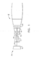
- the highly compressed air is delivered to combustor 16.
- Airflow from combustor 16 drives turbines 18 and 20 and exits gas turbine engine 10 through a nozzle 5.
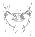
- FIG 2 is a partial cross-sectional view of an exemplary known combustor 30.
- Combustor 30 may be used with gas turbine engine 10 shown in Figure 1 , and includes a dome assembly 32.
- a fuel injector (not shown) extends into dome assembly 32 and injects atomized fuel through dome assembly 32 into a combustion zone 36 defined within combustor 30 to form an air-fuel mixture that is ignited downstream of the fuel injector
- Combustion zone 36 is formed by annular, radially outer and radially inner supporting members (not shown) and combustor liners 40.
- Combustor liners 40 shield the outer and inner supporting members from the heat generated within combustion zone 36 and includes an inner liner 42 and an outer liner 44. Liners 42 and 44 define combustion zone 36.
- Combustion zone 36 extends from dome assembly 32 downstream to a turbine nozzle (not shown). Outer liner 44 and inner liner 42 are each coupled to dome assembly 32 by a plurality of circumferentially-spaced fasteners 58.
- cowl assembly 60 is also coupled to dome assembly 32 by fasteners 58.
- cowl assembly 60 includes an outer cowl 62 and an inner cowl 64 that each include a plurality of circumferentially-spaced openings 66. Openings 66 extend through cowls 62 and 64 adjacent a respective trailing edge 70 and 72 of each cowl 62 and 64. Each opening 66 is sized to receive a respective fastener 58 therethrough.
- Cowls 62 and 64 extend upstream from dome assembly 32 and are aerodynamically contoured towards a center axis 73 of an air/fuel mixer assembly 74 coupled to dome assembly 32.
- each leading edge 76 and 78 of each respective cowl 62 and 64 define a generally annular opening 80 wherein compressed air is directed therethrough towards combustion chamber 30. More specifically, each leading edge 76 and 78 is rolled aftward at least partially around a continuous solid core wire 90. Wire 90 facilitates damping vibrations induced to cowls 62 and 64.
- cowls 62 and 64 are exposed to compressor discharge flow and may be impacted by chaotic perturbations in the impinging compressed air flow channeled into combustor 30.
- mechanical vibration may be induced into cowl assembly 60. More specifically, vibration resulting from these normal operating conditions may cause high cycle fatigue of cowls 62 and 64.
- a torsional frictional force is induced between wire 90 and cowls 62 and 64 to facilitate damping vibrational stresses induced to cowl assembly 60.
- continued exposure to such stresses may cause wire-damped or wire-wrapped cowls 62 and 64 to wear such that a gap is formed between wire 90 and cowls 62 and 64. More specifically, continued contact through the gap between cowl assembly 60 and wire 90 may frictionally thin wire 90 and deteriorate cowls 62 and 64.
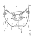
- Figure 3 is a cross-sectional view of combustor 30 including a cowl assembly 100 repaired and/or retrofitted in accordance with the methods described herein.
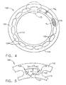
- Figure 4 is a forward looking aft view of cowl assembly 100.
- Figure 5 is a partial aft looking forward view of a portion of cowl assembly 100 taken along area 5-5 (shown in Figure 4 ).
- Cowl assembly 100 includes a portion 102 of cowl assembly 60 (shown in Figure 2 ) and includes a replacement cowl 104.
- Cowl 104 is a one-piece cowl and is coupled, as described in more detail below, to cowl assembly portion 102, such that cowl 104 extends upstream from cowl assembly portion 102.
- Cowl 104 includes an outer annular portion 110 and an inner annular portion 112 that are substantially concentric about a central cowl axis 114 extending through cowl assembly 100.
- Cowl portions 110 and 112 are aerodynamically contoured relative to central cowl axis 114.
- a plurality of radial members or ligaments 120 are circumferentially-spaced about cowl 104. More specifically, ligaments 120 extend between outer and inner annular portions 110 and 112 such that a plurality of openings 124 are defined between outer and inner annular portions 110 and 112, and between circumferentially adjacent ligaments 120.
- Each radial ligament 120 is variably sized to have a cross-sectional area A RL that facilitates providing a pre-desired structural support to cowl 104 and facilitates cowl assembly 100 operating at a pre-determined natural frequency that facilitates preventing cowl assembly 100 from failing in high cycle fatigue. More specifically, ligament areas A RL facilitate reducing high cycle fatigue (HCF) stress induced to cowl 104.
- each opening 124 is sized with a pre-determined cross-sectional area A O that enables each opening 124 to receive at least one fuel nozzle (not shown) therethrough.
- cowl 104 includes fifteen circumferentially-spaced openings 124.
- radial ligaments 120 and openings 124 are sized and configured with respect to each other to receive a pre-desired airflow therethrough during engine operations. More specifically, in the exemplary embodiment, ligament area A RL and opening area A O are interrelated such that a ratio A RL /A O between ligament area A RL and opening area A O is between approximately 2 and 7.
- openings 124 are also sized with a pre-determined radial height H and are rounded at each circumferential end 130. More specifically, each end 130 is formed with a pre-determined radius R. In the exemplary embodiment, a ratio H/R of opening radial height H to the end radius R is preferably between approximately 2 and 2.5.
- Cowls 62 and 64 (shown in Figure 2 ) are exposed to compressor discharge flow and may be impacted by chaotic perturbations in the impinging compressed air flow channeled into combustor 30. As the air flow contacts cowls 62 and 64, mechanical vibration may be induced into cowl assembly 60. More specifically, vibration resulting from these normal operating conditions may cause high cycle fatigue of cowls 62 and 64. A torsional frictional force induced between wire 90 (shown in Figure 2 ) and cowls 62 and 64 facilitates damping vibrational stresses induced to cowl assembly 60.
- cowl assembly 60 and wire 90 may frictionally thin wire 90 and deteriorate cowls 62 and 64.
- Deteriorated regions of combustor cowl 60 may be removed and replaced using the methods described herein. More specifically, the deteriorated wire-wrapped portion of cowl 60 may be removed and replaced using the methods described herein. If a field returned engine, such as engine 10, indicates that combustor cowl 60 includes a damaged or deteriorated wire-wrapped portion, a radial cut (illustrated as 150 in Figure 2 ) is made through outer cowl 62, and a similar cut (illustrated as 152 in Figure 2 ) is made through inner cowl 64 to enable deteriorated portions of outer and inner cowls 62 and 64, respectively, specifically, wire-wrapped portions of cowls 62 and 64, to be removed from combustor 30.
- a field returned engine such as engine 10
- a radial cut illustrated as 150 in Figure 2
- a similar cut illustrated as 152 in Figure 2
- each cut 150 and 152 extends radially through each respective cowl 62 and 64 between an exterior surface 156 and 158 to an interior surface 160 and 162 of each respective cowl 62 and 64. Accordingly, when deteriorated portions of cowl 62 and 64 have been removed, cowl assembly portion 102 remains.
- fasteners 58 are loosened from cowl assembly 60, and cowl assembly 60 is removed from combustor 30 prior to cuts 150 and 152 being formed.
- Replacement cowl 104 is then coupled to cowl assembly 60 to form cowl assembly 100. More specifically, when coupled to cowl assembly 60, an annular coupling joint 170 is formed between cowl 104 and cowl assembly portion 102, and cowl 104 extends upstream from cowl assembly portion 102.
- cowl 104 is coupled to cowl assembly portion 102 with a laser welding process.
- cowl 104 is coupled to cowl assembly portion 102 with a brazing process.
- cowl 104 is coupled to cowl assembly portion 102 using any suitable coupling method that enables cowl assembly 100 to function as described herein, such as but not limited to electron beam welding, and tungsten inert gas, TIG, welding.
- cowl assembly 100 When coupled within combustor 30 by fasteners 58, cowl assembly 100 performs the function of properly directing and regulating the flow of compressed air to combustion chamber 36 (shown in Figure 2 ). However, cowl 104 provides structural support to cowl assembly 100 such that one-piece cowl assembly 100 is more durable than cowl assembly 60. Furthermore, cowl 104 facilitates reducing stresses induced to cowl assembly 100 while preventing high cycle fatigue.
- combustors 30 are returned to service using a replacement/retrofit process that facilitates improved savings in comparison to removing and replacing entire cowl assemblies. Furthermore, because the replacement cowl is shaped to be substantially similar to the originally installed cowl assembly, aerodynamic performance and combustor performance are not adversely impacted by the replacement cowls.
- the above-described combustor liner replacement method is cost-effective and highly reliable.
- the methods include the steps of removing deteriorated wire-wrapped outer and inner cowls from the combustor, and replacing such cowls with a one-piece cowl assembly.
- the replacement cowl assembly facilitates reducing stresses induced to the cowl assembly, such that the useful life of the combustor is facilitated to be extended.
- methods are provided which enable deteriorated wire-wrapped mulit-piece combustor cowls to be removed and replaced in a cost-effective and reliable manner.
Landscapes
- Engineering & Computer Science (AREA)
- Mechanical Engineering (AREA)
- Chemical & Material Sciences (AREA)
- Combustion & Propulsion (AREA)
- General Engineering & Computer Science (AREA)
- Structures Of Non-Positive Displacement Pumps (AREA)
- Details Of Aerials (AREA)
- Laser Beam Processing (AREA)
- Turbine Rotor Nozzle Sealing (AREA)
Applications Claiming Priority (2)
| Application Number | Priority Date | Filing Date | Title |
|---|---|---|---|
| US436842 | 2003-05-13 | ||
| US10/436,842 US6779268B1 (en) | 2003-05-13 | 2003-05-13 | Outer and inner cowl-wire wrap to one piece cowl conversion |
Publications (2)
| Publication Number | Publication Date |
|---|---|
| EP1477741A1 EP1477741A1 (en) | 2004-11-17 |
| EP1477741B1 true EP1477741B1 (en) | 2011-02-02 |
Family
ID=32869281
Family Applications (1)
| Application Number | Title | Priority Date | Filing Date |
|---|---|---|---|
| EP04252732A Expired - Lifetime EP1477741B1 (en) | 2003-05-13 | 2004-05-12 | Outer and inner cowl-wire wrap to one piece cowl conversion |
Country Status (10)
| Country | Link |
|---|---|
| US (1) | US6779268B1 (enExample) |
| EP (1) | EP1477741B1 (enExample) |
| JP (1) | JP4643175B2 (enExample) |
| CN (1) | CN100549529C (enExample) |
| BR (1) | BRPI0402049A (enExample) |
| CA (1) | CA2465573C (enExample) |
| DE (1) | DE602004031275D1 (enExample) |
| MX (1) | MXPA04004473A (enExample) |
| MY (1) | MY135398A (enExample) |
| SG (1) | SG109532A1 (enExample) |
Families Citing this family (17)
| Publication number | Priority date | Publication date | Assignee | Title |
|---|---|---|---|---|
| US7316117B2 (en) * | 2005-02-04 | 2008-01-08 | Siemens Power Generation, Inc. | Can-annular turbine combustors comprising swirler assembly and base plate arrangements, and combinations |
| JP2006300448A (ja) * | 2005-04-22 | 2006-11-02 | Mitsubishi Heavy Ind Ltd | ガスタービンの燃焼器 |
| US7513098B2 (en) | 2005-06-29 | 2009-04-07 | Siemens Energy, Inc. | Swirler assembly and combinations of same in gas turbine engine combustors |
| US8327538B2 (en) * | 2005-10-17 | 2012-12-11 | General Electric Company | Methods to facilitate extending gas turbine engine useful life |
| FR2897144B1 (fr) * | 2006-02-08 | 2008-05-02 | Snecma Sa | Chambre de combustion de turbomachine a fentes tangentielles |
| FR2897145B1 (fr) * | 2006-02-08 | 2013-01-18 | Snecma | Chambre de combustion annulaire de turbomachine a fixations alternees. |
| US7716931B2 (en) * | 2006-03-01 | 2010-05-18 | General Electric Company | Method and apparatus for assembling gas turbine engine |
| US7765809B2 (en) * | 2006-11-10 | 2010-08-03 | General Electric Company | Combustor dome and methods of assembling such |
| FR2910597B1 (fr) * | 2006-12-22 | 2009-03-20 | Snecma Sa | Carenage pour fond de chambre de combustion |
| JP4495179B2 (ja) * | 2007-02-28 | 2010-06-30 | 三菱重工業株式会社 | 燃料ノズル装置、ガスタービンおよび燃料ノズル装置の制御方法 |
| US20080216300A1 (en) * | 2007-03-06 | 2008-09-11 | United Technologies Corporation | Splitter fairing repair |
| FR2943403B1 (fr) * | 2009-03-17 | 2014-11-14 | Snecma | Chambre de combustion de turbomachine comprenant des moyens ameliores d'alimentation en air |
| CN101560929B (zh) * | 2009-05-22 | 2010-08-25 | 中国科学院力学研究所 | 一种可变倾角超燃冲压发动机外整流罩 |
| US9316108B2 (en) * | 2012-03-05 | 2016-04-19 | General Electric Company | Gas turbine frame stiffening rails |
| US11175046B2 (en) | 2019-05-09 | 2021-11-16 | General Electric Company | Combustor premixer assembly including inlet lips |
| US11859819B2 (en) | 2021-10-15 | 2024-01-02 | General Electric Company | Ceramic composite combustor dome and liners |
| CN120734756B (zh) * | 2025-09-02 | 2025-11-04 | 江苏顺源航空零部件有限公司 | 发动机短舱组合式进气整流罩的智能化焊接系统及方法 |
Family Cites Families (20)
| Publication number | Priority date | Publication date | Assignee | Title |
|---|---|---|---|---|
| DE3942271A1 (de) * | 1989-12-21 | 1991-07-04 | Mtu Maintenance Gmbh | Verfahren zur reparatur eines flammrohres |
| US5197289A (en) * | 1990-11-26 | 1993-03-30 | General Electric Company | Double dome combustor |
| US5181377A (en) * | 1991-04-16 | 1993-01-26 | General Electric Company | Damped combustor cowl structure |
| US5430935A (en) * | 1993-07-14 | 1995-07-11 | Yaworsky; Chester E. | Method for repairing a combustion chamber assembly |
| DE19643028A1 (de) * | 1996-10-18 | 1998-04-23 | Bmw Rolls Royce Gmbh | Brennkammer einer Gasturbine mit einem ringförmigen Kopfabschnitt |
| US5974805A (en) | 1997-10-28 | 1999-11-02 | Rolls-Royce Plc | Heat shielding for a turbine combustor |
| US6148600A (en) | 1999-02-26 | 2000-11-21 | General Electric Company | One-piece sheet metal cowl for combustor of a gas turbine engine and method of configuring same |
| US6286302B1 (en) | 1999-04-01 | 2001-09-11 | General Electric Company | Venturi for use in the swirl cup package of a gas turbine combustor having water injected therein |
| US6205763B1 (en) | 1999-05-24 | 2001-03-27 | General Electric Company | Method of forming a swirler with as-cast holes |
| US6345441B1 (en) * | 2000-07-18 | 2002-02-12 | General Electric Company | Method of repairing combustion chamber liners |
| US6497104B1 (en) * | 2000-10-30 | 2002-12-24 | General Electric Company | Damped combustion cowl structure |
| US6449952B1 (en) * | 2001-04-17 | 2002-09-17 | General Electric Company | Removable cowl for gas turbine combustor |
| US6568079B2 (en) * | 2001-06-11 | 2003-05-27 | General Electric Company | Methods for replacing combustor liner panels |
| US6553767B2 (en) | 2001-06-11 | 2003-04-29 | General Electric Company | Gas turbine combustor liner with asymmetric dilution holes machined from a single piece form |
| US6655146B2 (en) * | 2001-07-31 | 2003-12-02 | General Electric Company | Hybrid film cooled combustor liner |
| US6513331B1 (en) * | 2001-08-21 | 2003-02-04 | General Electric Company | Preferential multihole combustor liner |
| US6581386B2 (en) * | 2001-09-29 | 2003-06-24 | General Electric Company | Threaded combustor baffle |
| US6629415B2 (en) * | 2001-10-27 | 2003-10-07 | General Electric Co. | Methods and apparatus for modeling gas turbine engine combustor liners |
| US6651437B2 (en) * | 2001-12-21 | 2003-11-25 | General Electric Company | Combustor liner and method for making thereof |
| US6655147B2 (en) * | 2002-04-10 | 2003-12-02 | General Electric Company | Annular one-piece corrugated liner for combustor of a gas turbine engine |
-
2003
- 2003-05-13 US US10/436,842 patent/US6779268B1/en not_active Expired - Lifetime
-
2004
- 2004-04-29 CA CA2465573A patent/CA2465573C/en not_active Expired - Fee Related
- 2004-05-11 SG SG200402536A patent/SG109532A1/en unknown
- 2004-05-11 MY MYPI20041749A patent/MY135398A/en unknown
- 2004-05-12 MX MXPA04004473A patent/MXPA04004473A/es active IP Right Grant
- 2004-05-12 BR BR0402049-9A patent/BRPI0402049A/pt not_active IP Right Cessation
- 2004-05-12 EP EP04252732A patent/EP1477741B1/en not_active Expired - Lifetime
- 2004-05-12 DE DE602004031275T patent/DE602004031275D1/de not_active Expired - Lifetime
- 2004-05-12 JP JP2004141751A patent/JP4643175B2/ja not_active Expired - Fee Related
- 2004-05-13 CN CNB2004100431812A patent/CN100549529C/zh not_active Expired - Lifetime
Also Published As
| Publication number | Publication date |
|---|---|
| CN1550716A (zh) | 2004-12-01 |
| SG109532A1 (en) | 2005-03-30 |
| CA2465573C (en) | 2011-04-19 |
| JP2004340143A (ja) | 2004-12-02 |
| EP1477741A1 (en) | 2004-11-17 |
| MY135398A (en) | 2008-04-30 |
| MXPA04004473A (es) | 2005-03-31 |
| CA2465573A1 (en) | 2004-11-13 |
| DE602004031275D1 (de) | 2011-03-17 |
| US6779268B1 (en) | 2004-08-24 |
| CN100549529C (zh) | 2009-10-14 |
| BRPI0402049A (pt) | 2005-01-25 |
| JP4643175B2 (ja) | 2011-03-02 |
Similar Documents
| Publication | Publication Date | Title |
|---|---|---|
| EP1477741B1 (en) | Outer and inner cowl-wire wrap to one piece cowl conversion | |
| US6511284B2 (en) | Methods and apparatus for minimizing gas turbine engine thermal stress | |
| US6568079B2 (en) | Methods for replacing combustor liner panels | |
| EP1266718B1 (en) | Methods for replacing nuggeted combustor liner panels | |
| EP3279567A1 (en) | A method of assembling an annular combustion chamber assembly | |
| CA2451303C (en) | Methods for replacing combustor liners | |
| US6904676B2 (en) | Methods for replacing a portion of a combustor liner | |
| CA2455266C (en) | Methods for replacing a portion of a combustor dome assembly | |
| US6844520B2 (en) | Methods for fabricating gas turbine engine combustors | |
| US12410916B2 (en) | Annular dome assembly for a combustor | |
| US6886343B2 (en) | Methods and apparatus for controlling engine clearance closures |
Legal Events
| Date | Code | Title | Description |
|---|---|---|---|
| PUAI | Public reference made under article 153(3) epc to a published international application that has entered the european phase |
Free format text: ORIGINAL CODE: 0009012 |
|
| AK | Designated contracting states |
Kind code of ref document: A1 Designated state(s): AT BE BG CH CY CZ DE DK EE ES FI FR GB GR HU IE IT LI LU MC NL PL PT RO SE SI SK TR |
|
| AX | Request for extension of the european patent |
Extension state: AL HR LT LV MK |
|
| 17P | Request for examination filed |
Effective date: 20050517 |
|
| AKX | Designation fees paid |
Designated state(s): DE FR GB IT |
|
| 17Q | First examination report despatched |
Effective date: 20061109 |
|
| GRAP | Despatch of communication of intention to grant a patent |
Free format text: ORIGINAL CODE: EPIDOSNIGR1 |
|
| RIC1 | Information provided on ipc code assigned before grant |
Ipc: F23M 99/00 20100101ALI20100705BHEP Ipc: B23P 6/00 20060101ALI20100705BHEP Ipc: F23R 3/60 20060101ALI20100705BHEP Ipc: F23R 3/52 20060101ALI20100705BHEP Ipc: F23R 3/00 20060101AFI20100705BHEP |
|
| GRAS | Grant fee paid |
Free format text: ORIGINAL CODE: EPIDOSNIGR3 |
|
| GRAA | (expected) grant |
Free format text: ORIGINAL CODE: 0009210 |
|
| AK | Designated contracting states |
Kind code of ref document: B1 Designated state(s): DE FR GB IT |
|
| REG | Reference to a national code |
Ref country code: GB Ref legal event code: FG4D |
|
| REF | Corresponds to: |
Ref document number: 602004031275 Country of ref document: DE Date of ref document: 20110317 Kind code of ref document: P |
|
| REG | Reference to a national code |
Ref country code: DE Ref legal event code: R096 Ref document number: 602004031275 Country of ref document: DE Effective date: 20110317 |
|
| PLBE | No opposition filed within time limit |
Free format text: ORIGINAL CODE: 0009261 |
|
| STAA | Information on the status of an ep patent application or granted ep patent |
Free format text: STATUS: NO OPPOSITION FILED WITHIN TIME LIMIT |
|
| 26N | No opposition filed |
Effective date: 20111103 |
|
| REG | Reference to a national code |
Ref country code: DE Ref legal event code: R097 Ref document number: 602004031275 Country of ref document: DE Effective date: 20111103 |
|
| REG | Reference to a national code |
Ref country code: FR Ref legal event code: PLFP Year of fee payment: 13 |
|
| REG | Reference to a national code |
Ref country code: FR Ref legal event code: PLFP Year of fee payment: 14 |
|
| REG | Reference to a national code |
Ref country code: FR Ref legal event code: PLFP Year of fee payment: 15 |
|
| PGFP | Annual fee paid to national office [announced via postgrant information from national office to epo] |
Ref country code: IT Payment date: 20200421 Year of fee payment: 17 |
|
| PG25 | Lapsed in a contracting state [announced via postgrant information from national office to epo] |
Ref country code: IT Free format text: LAPSE BECAUSE OF NON-PAYMENT OF DUE FEES Effective date: 20200512 |
|
| P01 | Opt-out of the competence of the unified patent court (upc) registered |
Effective date: 20230414 |
|
| PGFP | Annual fee paid to national office [announced via postgrant information from national office to epo] |
Ref country code: FR Payment date: 20230420 Year of fee payment: 20 Ref country code: DE Payment date: 20230419 Year of fee payment: 20 |
|
| PGFP | Annual fee paid to national office [announced via postgrant information from national office to epo] |
Ref country code: GB Payment date: 20230420 Year of fee payment: 20 |
|
| REG | Reference to a national code |
Ref country code: DE Ref legal event code: R071 Ref document number: 602004031275 Country of ref document: DE |
|
| REG | Reference to a national code |
Ref country code: GB Ref legal event code: PE20 Expiry date: 20240511 |
|
| PG25 | Lapsed in a contracting state [announced via postgrant information from national office to epo] |
Ref country code: GB Free format text: LAPSE BECAUSE OF EXPIRATION OF PROTECTION Effective date: 20240511 |
|
| PG25 | Lapsed in a contracting state [announced via postgrant information from national office to epo] |
Ref country code: GB Free format text: LAPSE BECAUSE OF EXPIRATION OF PROTECTION Effective date: 20240511 |
|
| PG25 | Lapsed in a contracting state [announced via postgrant information from national office to epo] |
Ref country code: IT Free format text: LAPSE BECAUSE OF NON-PAYMENT OF DUE FEES Effective date: 20210512 |