EP1477450A1 - A crane - Google Patents
A crane Download PDFInfo
- Publication number
- EP1477450A1 EP1477450A1 EP03445052A EP03445052A EP1477450A1 EP 1477450 A1 EP1477450 A1 EP 1477450A1 EP 03445052 A EP03445052 A EP 03445052A EP 03445052 A EP03445052 A EP 03445052A EP 1477450 A1 EP1477450 A1 EP 1477450A1
- Authority
- EP
- European Patent Office
- Prior art keywords
- arm
- wire
- link
- guide
- crane according
- Prior art date
- Legal status (The legal status is an assumption and is not a legal conclusion. Google has not performed a legal analysis and makes no representation as to the accuracy of the status listed.)
- Granted
Links
Images




Classifications
-
- B—PERFORMING OPERATIONS; TRANSPORTING
- B66—HOISTING; LIFTING; HAULING
- B66C—CRANES; LOAD-ENGAGING ELEMENTS OR DEVICES FOR CRANES, CAPSTANS, WINCHES, OR TACKLES
- B66C23/00—Cranes comprising essentially a beam, boom, or triangular structure acting as a cantilever and mounted for translatory of swinging movements in vertical or horizontal planes or a combination of such movements, e.g. jib-cranes, derricks, tower cranes
- B66C23/62—Constructional features or details
- B66C23/64—Jibs
- B66C23/68—Jibs foldable or otherwise adjustable in configuration
Definitions
- the present invention relates to a crane, comprising a first arm and a second arm that are interconnected, wherein the second arm is pivotally arranged in relation to the first arm, and wherein a longitudinal axis of the first arm and a longitudinal axis of the second arm extend in a common, plane which is also the pivot plane of the second arm, and comprising a winch device arranged on the first arm and provided with a wire, and a pulley device arranged on the second arm, and a wire guide arranged between the winch device and the pulley device, the wire extending from the winch via the wire guide to the pulley device.
- the crane according to the invention particularly belongs to the type of cranes that are used as piece goods cranes, for example on trucks and the like, and that comprises a hydraulic cylinder/ piston unit for pivoting the second arm in relation to the first arm, one end of said unit being connected to the first arm and the second end thereof being connected to the second arm.
- the crane belongs to the type of cranes where one of the arms, here the second arm, is pivotal in two opposite angular directions outgoing from the position in which the second arm is generally in alignment with the first arm.
- the second arm is pivotal more than 180° in one of the directions in order to permit it to be folded or pivoted into a position in which it extends beside the first arm, thereby reducing the total length of the first and second arms to a length corresponding to the one of the first arm.
- Wire guide should be regarded in broad sense and may include any kind of guide that is suitable for the purpose of re-directing or supporting a wire running from a winch on the first arm to a pulley on the second arm.
- pulley should be regarded in a broad sense, and may include any kind of guide member of re-directing member via which a wire end is connected to a crane hook or the like.
- the second arm is an end arm in a set of interconnected arms that form part of the crane according to the invention.
- the second arm, as well as the first arm, may be extendable and may comprise a plurality of sub-arms arranged in a telescopic manner.
- Prior art includes a solution by which a lifting winch is attached to a first arm and a pulley is attached to a second arm of a piece goods crane, the second arm being pivotal in relation the first arm by means of a hydraulic cylinder-piston unit.
- a wire guide that comprises a wire support roll is connected to the second arm.
- the wire guide is arranged generally in the common plane of the longitudinal axes of the first and second arms at a given distance from the second arm in order not to interfere with an adjacent cylinder-piston unit for generating the pivotation movement of the second arm.
- the second arm shall be able to pivot both above a common horizontal plane in which the longitudinal axes of both the first arm and the second arm extends when in alignment with each other, the horizontal plane being generally perpendicular to the pivotation plane of the second arm.
- the primary object of the invention is achieved by means of the initially defined crane, characterised in that the wire is guided by the wire guide in the region of the pivot centre between the first and second arm.
- the pivot centre is referred to as a line or axis around which the pivotation between the first and second arms takes place.
- the invention is not delimited to an embodiment in which the wire passes through the region of the pivot centre in the same plane as the common plane of the longitudinal axis of the first and second arms and the pivotation plane of the second arm.
- the secondary object of the invention is achieved by means of the inventive crane, further characterised in that the wire guide is laterally displaced with regard to said common plane, such that the wire extends laterally beside said second arm.
- the wire need not extend laterally beside the second arm all over the length thereof. If suffices that it extends so far a distance laterally that it goes free from vital operational parts such as any cylinder-piston unit arranged on the second arm. Off course, the wire must also be laterally displaced to such an extent that vital parts located along the first arm are not interfered by the wire.
- the winch may, but need not, be arranged generally in alignment with the first arm, i.e. not laterally displaced in relation to said common plane of the longitudinal axes of the first and second arms.
- the wire intersects the pivot axis in the region in which it is redirected by the wire guide.
- the wire guide comprises a first guide element and a second guide element with an intermediate spacing therebetween, the wire extending through said spacing and being mainly supported either by the first guide element or by the second guide element depending on the pivot angle between the first and second arms.
- full support is given by the wire guide also when pivotation angles above the horizontal plane (see definition above) are applied.
- the crane comprises a cylinder/ piston unit connected in one end to the second arm and connected in another end, via a first pivotal link, to the first arm, and comprising a second pivotal link that is connected in one end to the second arm and in another end to the first link, the wire guide being fastened to the second link.
- the second link is connected to the second arm via a first tap extending through the link and through the second arm, and to the first link via a second tap extending through the second link and through the first link, said first and second rolls being rotatably arranged on the first tap and the second tap respectively.
- the crane according to the invention comprises a first arm 1, a second arm 2, and a hydraulic cylinder-piston unit 3 for pivoting the second arm 2 in relation to the first arm 1. It further comprises a winch 4 attached to the first arm 1, a pulley 5 attached to a hook 6 at the remote free end of the second arm 2, and a wire guide 7 between the winch 4 and the pulley 5.
- the longitudinal axes of the first and second arms 1, 2 extend in a common vertical plane, which is also the pivotation plane of the second arm 2 when the crane is in an upright operative position.
- Running from the winch 4 to the pulley 5 is a wire 8, preferably made of steel.
- the wire 8 is wound on the winch 4 and runs through the pulley 5 to its free end, where it is attached to a hook 9.
- the second arm 2 is extendable since it consists of two sub-arms that are slidingly and telescopically arranged in relation to each other and the telescopic function is provided for by means of a hydraulic second cylinder-piston unit 10.
- Some kind of brake mechanism should also be arranged by the winch 4 for the purpose of preventing unwanted outlet of the wire 8.
- the winch 4 is arranged on the lower side of the first arm 1.
- the first arm 1 comprises a beam with a generally rectangular cross-section, the winch 4 accordingly being attached to the lower wall of said beam and pointing downwards from the arm 1 when the latter extends horizontally.
- the wire guide 7 comprises a first guide element 12 and a second guide element 13 with an intermediate spacing therebetween, the wire 8 extending through said spacing and being mainly supported either by the first guide element 12 or by the second guide element 13 depending on the pivot angle between the first and second arms 1,2.
- the first guide element 12 comprises a first roll
- the second guide element 13 comprises a second roll, said rolls being generally parallel to each other, and said spacing being present between the outer peripheries of the rolls 12, 13.
- the rolls are parallel to each other in the sense that the outer peripheries thereof, against which the wire 8 is supposed to rest, extend in a common plane. This plane is parallel to the common vertical plane of the longitudinal axes of the arms 1, 2, which is the same plane as the pivotation plane of the second arm 2.
- the diameter of each roll must be above a lower limit in order to prevent excessive bending of the wire in the bending zone in which it is re-directed by the rolls 12, 13.
- the wire is re-directed by the wire guide in the region of pivot centre axis of the second arm 2 in relation to the first arm 1.
- the pivot centre axis coincides with the centre axis of a shaft or tap 18 that penetrates the adjacent ends of the arms 1, 2 in a direction perpendicular to the pivotation plane of the second arm, thereby interconnecting said arms 1, 2.
- the wire 8 is in contact with, resting against the wire guide 7 at the point where it crosses the pivot centre axis region.
- the cylinder/piston unit 3 is connected in one end to the second arm 2 and connected in another end, via a first pivotal link 14, to the first arm 1.
- a second pivotal link 15 that is connected in one end to the second arm 2 and in another end to the first link 14, the wire guide 7 being connected to and fastened to the second link 15.
- the second link 15 comprises two shanks, one on each lateral side of the second arm 2. Said shanks are connected to each other by means of a first tap 16 extending through the first shank, laterally penetrating a hole in the second arm, and through the second shank of the second link 15.
- the shanks of second link 15 are also connected to each other by a second tap 17 extending laterally through the first shank, the first link 14 and the second shank.
- the first and second rolls 12, 13 are penetrated by and are arranged on the first tap 16 and the second tap 17 respectively, laterally outside said the adjacent shank of the second link 15.
- the pivotation centre axis coincides and is defined by a tap or shaft 18 extending through an end portion 19 of the first arm 1 and an end portion 20 of the second arm 2.
- End portion 20 of the first arm 1 comprises two shanks that are in overlapping engagement with corresponding shanks of end portion 20 of the second arm 2.
- the pivotation centre axis intersects the second link 15 approximately in the middle between the first tap 16 and the second tap 17 thereof.
- the pivotation centre axis crosses a region in which the spacing between the first and second guide elements 12, 13 is at a minimum, given that the width or diameter of the guide elements 12, 13 is equal and that the holes for the taps 16, 17 in the second link 15 are at equal distance from the point where the link is intersected by the pivotation centre axis and on opposite sides of that point along a straight line.
- other solutions resulting in a re-direction of the wire through the pivotation centre of the arm 1, 2 are also within the scope of the invention.
- the guide elements 12, 13 need not be attached to a link as described above.
- the arms are not even connected to each other by means of links. Then, any other separate suspension or fixation arrangement for the wire guide may be provided.
Landscapes
- Engineering & Computer Science (AREA)
- Mechanical Engineering (AREA)
- Jib Cranes (AREA)
- Iron Core Of Rotating Electric Machines (AREA)
Abstract
Description
- The present invention relates to a crane, comprising a first arm and a second arm that are interconnected, wherein the second arm is pivotally arranged in relation to the first arm, and wherein a longitudinal axis of the first arm and a longitudinal axis of the second arm extend in a common, plane which is also the pivot plane of the second arm, and comprising a winch device arranged on the first arm and provided with a wire, and a pulley device arranged on the second arm, and a wire guide arranged between the winch device and the pulley device, the wire extending from the winch via the wire guide to the pulley device.
- The crane according to the invention particularly belongs to the type of cranes that are used as piece goods cranes, for example on trucks and the like, and that comprises a hydraulic cylinder/ piston unit for pivoting the second arm in relation to the first arm, one end of said unit being connected to the first arm and the second end thereof being connected to the second arm.
- In particular the crane belongs to the type of cranes where one of the arms, here the second arm, is pivotal in two opposite angular directions outgoing from the position in which the second arm is generally in alignment with the first arm. Preferably, the second arm is pivotal more than 180° in one of the directions in order to permit it to be folded or pivoted into a position in which it extends beside the first arm, thereby reducing the total length of the first and second arms to a length corresponding to the one of the first arm.
- "Wire guide" should be regarded in broad sense and may include any kind of guide that is suitable for the purpose of re-directing or supporting a wire running from a winch on the first arm to a pulley on the second arm.
- Also the term "pulley should be regarded in a broad sense, and may include any kind of guide member of re-directing member via which a wire end is connected to a crane hook or the like.
- In the particular, the second arm is an end arm in a set of interconnected arms that form part of the crane according to the invention. The second arm, as well as the first arm, may be extendable and may comprise a plurality of sub-arms arranged in a telescopic manner.
- In the context of this invention "winch" may also be referred to as "lifting winch".
- By piece goods cranes of today an end arm, the remote arm, in a set of interconnected arms forming part of the crane is often pivotal in two opposite angular directions outgoing from the position in which the arm in question is generally in alignment with the adjacent arm. In other words, both negative and positive angles between the end arm and the adjacent arm are possible outgoing from the position in which these arms are generally in alignment with each other.
- Since there are crane operations by which it is desirable to lift an object by means of a wire from the crane rather than by means of a hook or the like that is directly attached to the end of the crane, it is also desirable to provide a winch solution that permits a wire to be guided from a winch on the adjacent arm to a pulley arranged at the free end of an end arm such as a jib, and that permits the end arm to be pivoted to both negative and positive angles in relation to the adjacent arm without the wire interfering with the second arm or with a cylinder-piston unit for pivoting the end arm in relation to the adjacent arm.
- It is also desirable to have a crane that permits pivotation of the second arm in relation to the first arm without thereby having a change in the wire length required between the winch and the pulley device. In other words, it is desirable to avoid length changes of the wire during pivotation of the second arm.
- Prior art includes a solution by which a lifting winch is attached to a first arm and a pulley is attached to a second arm of a piece goods crane, the second arm being pivotal in relation the first arm by means of a hydraulic cylinder-piston unit. A wire guide that comprises a wire support roll is connected to the second arm. There is also provided a second roll, the task of which is to act as a guide aid for preventing the wire from loosing its engagement with the first roll, which is the main guide element. The wire guide is arranged generally in the common plane of the longitudinal axes of the first and second arms at a given distance from the second arm in order not to interfere with an adjacent cylinder-piston unit for generating the pivotation movement of the second arm.
- However, the position and arrangement of the wire guide according to prior art necessitates an adjustment of the wire length between the winch and the pulley if the second arm is pivoted and a given wire length from the pulley to the wire end is to be kept constant.
- It is a primary object of the present invention to present a crane as initially defined that does not necessitate an adjustment of the wire length between the winch and the pulley if the second arm is pivoted and a given wire length from the pulley to the wire end is to be kept constant.
- Further, it is an object of the present invention to present a crane as initially defined the wire of which does not interfere with any cylinder-piston unit or any other vital part of the crane irrespectively of the pivotation direction of the second arm, outgoing from a position in which the second arm is generally in alignment with the first arm. In other words, the second arm shall be able to pivot both above a common horizontal plane in which the longitudinal axes of both the first arm and the second arm extends when in alignment with each other, the horizontal plane being generally perpendicular to the pivotation plane of the second arm.
- The primary object of the invention is achieved by means of the initially defined crane, characterised in that the wire is guided by the wire guide in the region of the pivot centre between the first and second arm. The pivot centre is referred to as a line or axis around which the pivotation between the first and second arms takes place. The invention is not delimited to an embodiment in which the wire passes through the region of the pivot centre in the same plane as the common plane of the longitudinal axis of the first and second arms and the pivotation plane of the second arm.
- According to a preferred embodiment the secondary object of the invention is achieved by means of the inventive crane, further characterised in that the wire guide is laterally displaced with regard to said common plane, such that the wire extends laterally beside said second arm. The wire need not extend laterally beside the second arm all over the length thereof. If suffices that it extends so far a distance laterally that it goes free from vital operational parts such as any cylinder-piston unit arranged on the second arm. Off course, the wire must also be laterally displaced to such an extent that vital parts located along the first arm are not interfered by the wire. The winch may, but need not, be arranged generally in alignment with the first arm, i.e. not laterally displaced in relation to said common plane of the longitudinal axes of the first and second arms.
- According to yet another preferred embodiment the wire intersects the pivot axis in the region in which it is redirected by the wire guide. By actually letting the wire go through or pass very close to the pivotation centre axis a minimum of wire length change, if any, will be needed during operation when the second arm is pivoted and the length of wire between pulley and free wire end is to be kept constant.
- Preferably, the wire guide comprises a first guide element and a second guide element with an intermediate spacing therebetween, the wire extending through said spacing and being mainly supported either by the first guide element or by the second guide element depending on the pivot angle between the first and second arms. Thereby, full support is given by the wire guide also when pivotation angles above the horizontal plane (see definition above) are applied.
- According to a preferred embodiment, the crane comprises a cylinder/ piston unit connected in one end to the second arm and connected in another end, via a first pivotal link, to the first arm, and comprising a second pivotal link that is connected in one end to the second arm and in another end to the first link, the wire guide being fastened to the second link. By connecting the wire guide directly to this link, advantage is taken of a component already existing on the crane for the purpose of positioning the wire guide.
- Preferably, the second link is connected to the second arm via a first tap extending through the link and through the second arm, and to the first link via a second tap extending through the second link and through the first link, said first and second rolls being rotatably arranged on the first tap and the second tap respectively.
- Further features and advantages of the present invention are disclosed in the remaining dependent claims as well as in the following detailed description of the invention.
- The invention will be further described by way of example with regard to the following drawings, on which:
- Fig. 1 is a perspective view of a crane according to the invention,
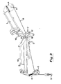
- Fig. 2 is a side view of the crane in fig. 1, from a first direction,
- Fig. 3 is a side view of the crane in fig. 2, from an opposite direction and in a different pivotal position,
- Fig. 4 is a view from below of the crane according to figs. 1-3, and
- Fig. 5 is a side view of a crane according to prior art.
-
- The crane according to the invention comprises a first arm 1, a
second arm 2, and a hydraulic cylinder-piston unit 3 for pivoting thesecond arm 2 in relation to the first arm 1. It further comprises awinch 4 attached to the first arm 1, apulley 5 attached to ahook 6 at the remote free end of thesecond arm 2, and awire guide 7 between thewinch 4 and thepulley 5. The longitudinal axes of the first andsecond arms 1, 2 extend in a common vertical plane, which is also the pivotation plane of thesecond arm 2 when the crane is in an upright operative position. - Running from the
winch 4 to thepulley 5 is awire 8, preferably made of steel. Thewire 8 is wound on thewinch 4 and runs through thepulley 5 to its free end, where it is attached to ahook 9. - The
second arm 2 is extendable since it consists of two sub-arms that are slidingly and telescopically arranged in relation to each other and the telescopic function is provided for by means of a hydraulic second cylinder-piston unit 10. - Preferably, there is provided a powered, e.g. electrically or hydraulically,
motor 11 on thewinch 4 for the purpose of winching thewire 8. Some kind of brake mechanism (not shown) should also be arranged by thewinch 4 for the purpose of preventing unwanted outlet of thewire 8. - The
winch 4 is arranged on the lower side of the first arm 1. Here, the first arm 1 comprises a beam with a generally rectangular cross-section, thewinch 4 accordingly being attached to the lower wall of said beam and pointing downwards from the arm 1 when the latter extends horizontally. - The
wire guide 7 comprises afirst guide element 12 and asecond guide element 13 with an intermediate spacing therebetween, thewire 8 extending through said spacing and being mainly supported either by thefirst guide element 12 or by thesecond guide element 13 depending on the pivot angle between the first andsecond arms 1,2. Here, thefirst guide element 12 comprises a first roll and thesecond guide element 13 comprises a second roll, said rolls being generally parallel to each other, and said spacing being present between the outer peripheries of therolls wire 8 is supposed to rest, extend in a common plane. This plane is parallel to the common vertical plane of the longitudinal axes of thearms 1, 2, which is the same plane as the pivotation plane of thesecond arm 2. When the wire is a steel wire, the diameter of each roll must be above a lower limit in order to prevent excessive bending of the wire in the bending zone in which it is re-directed by therolls - The wire is re-directed by the wire guide in the region of pivot centre axis of the
second arm 2 in relation to the first arm 1. The pivot centre axis coincides with the centre axis of a shaft or tap 18 that penetrates the adjacent ends of thearms 1, 2 in a direction perpendicular to the pivotation plane of the second arm, thereby interconnecting saidarms 1, 2. Preferably, thewire 8 is in contact with, resting against thewire guide 7 at the point where it crosses the pivot centre axis region. - The cylinder/
piston unit 3 is connected in one end to thesecond arm 2 and connected in another end, via a firstpivotal link 14, to the first arm 1. There is also a secondpivotal link 15 that is connected in one end to thesecond arm 2 and in another end to thefirst link 14, thewire guide 7 being connected to and fastened to thesecond link 15. Thesecond link 15 comprises two shanks, one on each lateral side of thesecond arm 2. Said shanks are connected to each other by means of afirst tap 16 extending through the first shank, laterally penetrating a hole in the second arm, and through the second shank of thesecond link 15. The shanks ofsecond link 15 are also connected to each other by asecond tap 17 extending laterally through the first shank, thefirst link 14 and the second shank. - The first and
second rolls first tap 16 and thesecond tap 17 respectively, laterally outside said the adjacent shank of thesecond link 15. The pivotation centre axis coincides and is defined by a tap orshaft 18 extending through anend portion 19 of the first arm 1 and anend portion 20 of thesecond arm 2.End portion 20 of the first arm 1 comprises two shanks that are in overlapping engagement with corresponding shanks ofend portion 20 of thesecond arm 2. The pivotation centre axis intersects thesecond link 15 approximately in the middle between thefirst tap 16 and thesecond tap 17 thereof. Thus, the pivotation centre axis crosses a region in which the spacing between the first andsecond guide elements guide elements taps second link 15 are at equal distance from the point where the link is intersected by the pivotation centre axis and on opposite sides of that point along a straight line. Off course, other solutions, resulting in a re-direction of the wire through the pivotation centre of thearm 1, 2 are also within the scope of the invention. - It should be realised that the above presentation of the invention has been made by way of example, and that alternative embodiments will be obvious for a man skilled in the art. However, the scope of protection claimed is defined in the patent claims supported by the description and the annexed drawings.
- For example, the
guide elements
Claims (9)
- A crane, comprising a first arm (1) and a second arm (2) that are interconnected,
wherein the second arm (2) is pivotally arranged in relation to the first arm (1),
and wherein a longitudinal axis of the first arm (1) and a longitudinal axis of the second arm (2) extend in a common, plane which is also the pivot plane of the second arm (2),
and comprising a winch device (4) arranged on the first arm (1) and provided with a wire (8),
a pulley device (5) arranged on the second arm (2),
and a wire guide (7) arranged between the winch device (4) and the pulley device (5),
the wire (8) extending from the winch device (4) via the wire guide (7) to the pulley device (5), characterised in that the wire (8) is guided by the wire guide (7) in the region of the pivot centre between the first and second arm (2). - A crane according to claim 1, characterised in that the wire guide (7) is laterally displaced with regard to said common plane, such that the wire (8) extends laterally beside said second arm (2).
- A crane according to claim 2, characterised in that the wire (8) intersects the pivot centre axis in the region in which it is redirected by the wire guide (7).
- A crane according to any one of claims 1-3, characterised in that the wire guide (7) comprises a first guide element (12) and a second guide element (13) with an intermediate spacing therebetween, the wire (8) extending through said spacing and being mainly supported either by the first guide element (12) or by the second guide element (13) depending on the pivot angle between the first and second arms (1,2).
- A crane according to any one of claims 1-4, characterised in that at least one of the first and second guide element (12, 13) comprises a rotational roll, around the periphery of which the wire (8) is re-directed.
- A crane according to claim 4 or 5, characterised in that the first guide element (12) comprises a first roll and that the second guide element (13) comprises a second roll, said rolls being generally parallel to each other, and said spacing being present between the outer peripheries of the rolls (12, 13).
- A crane according to claim 5 or 6, characterised in that the pivot centre axis crosses a region in which the spacing between the first and second guide elements (12, 13) is at a minimum.
- A crane according to any one of claims 1-7, characterised in that it comprises a cylinder/piston unit connected in one end to the second arm (2) and connected in another end, via a first pivotable link (14), to the first arm (1), and comprising a second pivotable link (15) that is connected in one end to the second arm (2) and in another end to the first link (14), the wire guide (7) being fastened to the second link (15).
- A crane according to claim 8, characterised in that the second link (15) is connected to the second arm (2) via a first tap (16) extending through the link (15) and through the second arm (2), and to the first link (14) via a second tap (17) extending through the second link (15) and through the first link (14), said first and second rolls (12, 13) being arranged on the first tap (16) and the second tap (17) respectively.
Priority Applications (4)
| Application Number | Priority Date | Filing Date | Title |
|---|---|---|---|
| DE60308152T DE60308152T2 (en) | 2003-04-30 | 2003-04-30 | crane |
| ES03445052T ES2272935T3 (en) | 2003-04-30 | 2003-04-30 | A CRANE |
| EP03445052A EP1477450B1 (en) | 2003-04-30 | 2003-04-30 | A crane |
| AT03445052T ATE338727T1 (en) | 2003-04-30 | 2003-04-30 | CRANE |
Applications Claiming Priority (1)
| Application Number | Priority Date | Filing Date | Title |
|---|---|---|---|
| EP03445052A EP1477450B1 (en) | 2003-04-30 | 2003-04-30 | A crane |
Publications (2)
| Publication Number | Publication Date |
|---|---|
| EP1477450A1 true EP1477450A1 (en) | 2004-11-17 |
| EP1477450B1 EP1477450B1 (en) | 2006-09-06 |
Family
ID=33017054
Family Applications (1)
| Application Number | Title | Priority Date | Filing Date |
|---|---|---|---|
| EP03445052A Expired - Lifetime EP1477450B1 (en) | 2003-04-30 | 2003-04-30 | A crane |
Country Status (4)
| Country | Link |
|---|---|
| EP (1) | EP1477450B1 (en) |
| AT (1) | ATE338727T1 (en) |
| DE (1) | DE60308152T2 (en) |
| ES (1) | ES2272935T3 (en) |
Cited By (9)
| Publication number | Priority date | Publication date | Assignee | Title |
|---|---|---|---|---|
| WO2008134783A1 (en) * | 2007-05-03 | 2008-11-13 | Palfinger Ag | Adjusting mechanism for a winch |
| EP2377803A1 (en) * | 2010-04-14 | 2011-10-19 | Palfinger AG | Loading crane with rope guidance device |
| CN102358581A (en) * | 2011-09-14 | 2012-02-22 | 哈尔滨东建机械制造有限公司 | Single-rope three-section type horizontal suspension arm folding buffering and self-locking device |
| CN102431910A (en) * | 2011-12-12 | 2012-05-02 | 廊坊凯博建设机械科技有限公司 | Arm rack overhead automatic folding and unfolding mechanism of tri-fold arm tower crane and folding and unfolding method thereof |
| WO2014200354A1 (en) * | 2012-06-06 | 2014-12-18 | Seaonicas As | Hybrid crane |
| CN108275586A (en) * | 2018-03-01 | 2018-07-13 | 徐州昊意工程机械科技有限公司 | A kind of telescopic crane boom of link chain mechanism |
| KR20180100858A (en) | 2017-03-02 | 2018-09-12 | 주식회사수산중공업 | Crane |
| CN110626963A (en) * | 2019-08-23 | 2019-12-31 | 中联重科股份有限公司 | Knuckle boom retracting device, crane and method for deploying the knuckle boom retracting device |
| EP4186850A1 (en) | 2021-11-24 | 2023-05-31 | Hiab AB | Telescopic arm |
Citations (3)
| Publication number | Priority date | Publication date | Assignee | Title |
|---|---|---|---|---|
| US4241837A (en) * | 1979-04-06 | 1980-12-30 | Don Suverkrop | Convertible articulated crane |
| EP0970914A2 (en) * | 1998-07-07 | 2000-01-12 | MANNESMANN Aktiengesellschaft | Mobile crane with telescopic jib |
| EP1291312A2 (en) * | 2001-09-05 | 2003-03-12 | Allebroer Leo Alix De Lille | A device for handling a load |
-
2003
- 2003-04-30 EP EP03445052A patent/EP1477450B1/en not_active Expired - Lifetime
- 2003-04-30 ES ES03445052T patent/ES2272935T3/en not_active Expired - Lifetime
- 2003-04-30 AT AT03445052T patent/ATE338727T1/en active
- 2003-04-30 DE DE60308152T patent/DE60308152T2/en not_active Expired - Lifetime
Patent Citations (3)
| Publication number | Priority date | Publication date | Assignee | Title |
|---|---|---|---|---|
| US4241837A (en) * | 1979-04-06 | 1980-12-30 | Don Suverkrop | Convertible articulated crane |
| EP0970914A2 (en) * | 1998-07-07 | 2000-01-12 | MANNESMANN Aktiengesellschaft | Mobile crane with telescopic jib |
| EP1291312A2 (en) * | 2001-09-05 | 2003-03-12 | Allebroer Leo Alix De Lille | A device for handling a load |
Cited By (11)
| Publication number | Priority date | Publication date | Assignee | Title |
|---|---|---|---|---|
| WO2008134783A1 (en) * | 2007-05-03 | 2008-11-13 | Palfinger Ag | Adjusting mechanism for a winch |
| US8113363B2 (en) | 2007-05-03 | 2012-02-14 | Palfinger Ag | Adjusting mechanism for a winch |
| EP2377803A1 (en) * | 2010-04-14 | 2011-10-19 | Palfinger AG | Loading crane with rope guidance device |
| CN102358581A (en) * | 2011-09-14 | 2012-02-22 | 哈尔滨东建机械制造有限公司 | Single-rope three-section type horizontal suspension arm folding buffering and self-locking device |
| CN102431910A (en) * | 2011-12-12 | 2012-05-02 | 廊坊凯博建设机械科技有限公司 | Arm rack overhead automatic folding and unfolding mechanism of tri-fold arm tower crane and folding and unfolding method thereof |
| WO2014200354A1 (en) * | 2012-06-06 | 2014-12-18 | Seaonicas As | Hybrid crane |
| US10259692B2 (en) | 2012-06-06 | 2019-04-16 | Seaonicas As | Hybrid crane |
| KR20180100858A (en) | 2017-03-02 | 2018-09-12 | 주식회사수산중공업 | Crane |
| CN108275586A (en) * | 2018-03-01 | 2018-07-13 | 徐州昊意工程机械科技有限公司 | A kind of telescopic crane boom of link chain mechanism |
| CN110626963A (en) * | 2019-08-23 | 2019-12-31 | 中联重科股份有限公司 | Knuckle boom retracting device, crane and method for deploying the knuckle boom retracting device |
| EP4186850A1 (en) | 2021-11-24 | 2023-05-31 | Hiab AB | Telescopic arm |
Also Published As
| Publication number | Publication date |
|---|---|
| EP1477450B1 (en) | 2006-09-06 |
| DE60308152D1 (en) | 2006-10-19 |
| DE60308152T2 (en) | 2007-09-20 |
| ES2272935T3 (en) | 2007-05-01 |
| ATE338727T1 (en) | 2006-09-15 |
Similar Documents
| Publication | Publication Date | Title |
|---|---|---|
| US7537126B2 (en) | Crane | |
| EP1477450B1 (en) | A crane | |
| US7753640B2 (en) | Boom foot pin attachment and detachment apparatus for construction machine | |
| JP2015155352A (en) | Connector, combination crane, and connection method using the connector | |
| US4976361A (en) | Mobile crane comprising a telescopic boom | |
| SI24539A (en) | Logging winch with improved management of stretching a rope in the area of upper pulley | |
| US5004108A (en) | Cranes | |
| JP2019031340A (en) | Assembled state confirmation device of luffing jib | |
| US7219810B2 (en) | Mobile crane with elongated boom | |
| US10519010B2 (en) | Crane | |
| EP0726872B1 (en) | Outer-boom crane | |
| US20190093309A1 (en) | Arrangement in the hoisting apparatus of a work machine, hoisting apparatus of a work machine, and work machine | |
| AU757444B2 (en) | Multi-position low profile boom nose | |
| US9327948B2 (en) | Telescopic boom | |
| AU1880902A (en) | Jib crane | |
| KR100301942B1 (en) | Crane | |
| EP3872022A1 (en) | A telescopic boom, and a crane and a vehicle provided with the telescopic boom | |
| GB2158041A (en) | Luffing mechanism for jib-type cranes, particularly cranes with a telescopic jib | |
| JP4177913B2 (en) | Mobile crane with luffing jib | |
| US2754011A (en) | Cable guides for crane booms | |
| EP4186850B1 (en) | Telescopic arm | |
| JP2020152501A (en) | Front strut backstop | |
| JP7293921B2 (en) | Pin anti-rotation structure | |
| KR20020066130A (en) | Boom for crane vehicle | |
| JP2507263Y2 (en) | Flexible material guide device used for folding boom |
Legal Events
| Date | Code | Title | Description |
|---|---|---|---|
| PUAI | Public reference made under article 153(3) epc to a published international application that has entered the european phase |
Free format text: ORIGINAL CODE: 0009012 |
|
| 17P | Request for examination filed |
Effective date: 20040408 |
|
| AK | Designated contracting states |
Kind code of ref document: A1 Designated state(s): AT BE BG CH CY CZ DE DK EE ES FI FR GB GR HU IE IT LI LU MC NL PT RO SE SI SK TR |
|
| AX | Request for extension of the european patent |
Extension state: AL LT LV MK |
|
| AKX | Designation fees paid |
Designated state(s): AT BE BG CH CY CZ DE DK EE ES FI FR GB GR HU IE IT LI LU MC NL PT RO SE SI SK TR |
|
| GRAP | Despatch of communication of intention to grant a patent |
Free format text: ORIGINAL CODE: EPIDOSNIGR1 |
|
| GRAS | Grant fee paid |
Free format text: ORIGINAL CODE: EPIDOSNIGR3 |
|
| GRAF | Information related to payment of grant fee modified |
Free format text: ORIGINAL CODE: EPIDOSCIGR3 |
|
| GRAA | (expected) grant |
Free format text: ORIGINAL CODE: 0009210 |
|
| AK | Designated contracting states |
Kind code of ref document: B1 Designated state(s): AT BE BG CH CY CZ DE DK EE ES FI FR GB GR HU IE IT LI LU MC NL PT RO SE SI SK TR |
|
| PG25 | Lapsed in a contracting state [announced via postgrant information from national office to epo] |
Ref country code: IT Free format text: LAPSE BECAUSE OF FAILURE TO SUBMIT A TRANSLATION OF THE DESCRIPTION OR TO PAY THE FEE WITHIN THE PRESCRIBED TIME-LIMIT;WARNING: LAPSES OF ITALIAN PATENTS WITH EFFECTIVE DATE BEFORE 2007 MAY HAVE OCCURRED AT ANY TIME BEFORE 2007. THE CORRECT EFFECTIVE DATE MAY BE DIFFERENT FROM THE ONE RECORDED. Effective date: 20060906 Ref country code: BE Free format text: LAPSE BECAUSE OF FAILURE TO SUBMIT A TRANSLATION OF THE DESCRIPTION OR TO PAY THE FEE WITHIN THE PRESCRIBED TIME-LIMIT Effective date: 20060906 Ref country code: SI Free format text: LAPSE BECAUSE OF FAILURE TO SUBMIT A TRANSLATION OF THE DESCRIPTION OR TO PAY THE FEE WITHIN THE PRESCRIBED TIME-LIMIT Effective date: 20060906 Ref country code: CZ Free format text: LAPSE BECAUSE OF FAILURE TO SUBMIT A TRANSLATION OF THE DESCRIPTION OR TO PAY THE FEE WITHIN THE PRESCRIBED TIME-LIMIT Effective date: 20060906 Ref country code: RO Free format text: LAPSE BECAUSE OF FAILURE TO SUBMIT A TRANSLATION OF THE DESCRIPTION OR TO PAY THE FEE WITHIN THE PRESCRIBED TIME-LIMIT Effective date: 20060906 Ref country code: LI Free format text: LAPSE BECAUSE OF FAILURE TO SUBMIT A TRANSLATION OF THE DESCRIPTION OR TO PAY THE FEE WITHIN THE PRESCRIBED TIME-LIMIT Effective date: 20060906 Ref country code: NL Free format text: LAPSE BECAUSE OF FAILURE TO SUBMIT A TRANSLATION OF THE DESCRIPTION OR TO PAY THE FEE WITHIN THE PRESCRIBED TIME-LIMIT Effective date: 20060906 Ref country code: SK Free format text: LAPSE BECAUSE OF FAILURE TO SUBMIT A TRANSLATION OF THE DESCRIPTION OR TO PAY THE FEE WITHIN THE PRESCRIBED TIME-LIMIT Effective date: 20060906 Ref country code: FI Free format text: LAPSE BECAUSE OF FAILURE TO SUBMIT A TRANSLATION OF THE DESCRIPTION OR TO PAY THE FEE WITHIN THE PRESCRIBED TIME-LIMIT Effective date: 20060906 Ref country code: CH Free format text: LAPSE BECAUSE OF FAILURE TO SUBMIT A TRANSLATION OF THE DESCRIPTION OR TO PAY THE FEE WITHIN THE PRESCRIBED TIME-LIMIT Effective date: 20060906 |
|
| REG | Reference to a national code |
Ref country code: GB Ref legal event code: FG4D |
|
| REG | Reference to a national code |
Ref country code: CH Ref legal event code: EP |
|
| REG | Reference to a national code |
Ref country code: IE Ref legal event code: FG4D |
|
| REF | Corresponds to: |
Ref document number: 60308152 Country of ref document: DE Date of ref document: 20061019 Kind code of ref document: P |
|
| PG25 | Lapsed in a contracting state [announced via postgrant information from national office to epo] |
Ref country code: SE Free format text: LAPSE BECAUSE OF FAILURE TO SUBMIT A TRANSLATION OF THE DESCRIPTION OR TO PAY THE FEE WITHIN THE PRESCRIBED TIME-LIMIT Effective date: 20061206 Ref country code: DK Free format text: LAPSE BECAUSE OF FAILURE TO SUBMIT A TRANSLATION OF THE DESCRIPTION OR TO PAY THE FEE WITHIN THE PRESCRIBED TIME-LIMIT Effective date: 20061206 Ref country code: BG Free format text: LAPSE BECAUSE OF FAILURE TO SUBMIT A TRANSLATION OF THE DESCRIPTION OR TO PAY THE FEE WITHIN THE PRESCRIBED TIME-LIMIT Effective date: 20061206 |
|
| PG25 | Lapsed in a contracting state [announced via postgrant information from national office to epo] |
Ref country code: PT Free format text: LAPSE BECAUSE OF FAILURE TO SUBMIT A TRANSLATION OF THE DESCRIPTION OR TO PAY THE FEE WITHIN THE PRESCRIBED TIME-LIMIT Effective date: 20070219 |
|
| NLV1 | Nl: lapsed or annulled due to failure to fulfill the requirements of art. 29p and 29m of the patents act | ||
| REG | Reference to a national code |
Ref country code: CH Ref legal event code: PL |
|
| REG | Reference to a national code |
Ref country code: ES Ref legal event code: FG2A Ref document number: 2272935 Country of ref document: ES Kind code of ref document: T3 |
|
| EN | Fr: translation not filed | ||
| PLBE | No opposition filed within time limit |
Free format text: ORIGINAL CODE: 0009261 |
|
| STAA | Information on the status of an ep patent application or granted ep patent |
Free format text: STATUS: NO OPPOSITION FILED WITHIN TIME LIMIT |
|
| 26N | No opposition filed |
Effective date: 20070607 |
|
| GBPC | Gb: european patent ceased through non-payment of renewal fee |
Effective date: 20070430 |
|
| PG25 | Lapsed in a contracting state [announced via postgrant information from national office to epo] |
Ref country code: FR Free format text: LAPSE BECAUSE OF FAILURE TO SUBMIT A TRANSLATION OF THE DESCRIPTION OR TO PAY THE FEE WITHIN THE PRESCRIBED TIME-LIMIT Effective date: 20070511 Ref country code: GB Free format text: LAPSE BECAUSE OF NON-PAYMENT OF DUE FEES Effective date: 20070430 Ref country code: GR Free format text: LAPSE BECAUSE OF FAILURE TO SUBMIT A TRANSLATION OF THE DESCRIPTION OR TO PAY THE FEE WITHIN THE PRESCRIBED TIME-LIMIT Effective date: 20061207 |
|
| PG25 | Lapsed in a contracting state [announced via postgrant information from national office to epo] |
Ref country code: IE Free format text: LAPSE BECAUSE OF NON-PAYMENT OF DUE FEES Effective date: 20070430 |
|
| PG25 | Lapsed in a contracting state [announced via postgrant information from national office to epo] |
Ref country code: EE Free format text: LAPSE BECAUSE OF FAILURE TO SUBMIT A TRANSLATION OF THE DESCRIPTION OR TO PAY THE FEE WITHIN THE PRESCRIBED TIME-LIMIT Effective date: 20060906 |
|
| PG25 | Lapsed in a contracting state [announced via postgrant information from national office to epo] |
Ref country code: FR Free format text: LAPSE BECAUSE OF FAILURE TO SUBMIT A TRANSLATION OF THE DESCRIPTION OR TO PAY THE FEE WITHIN THE PRESCRIBED TIME-LIMIT Effective date: 20060906 |
|
| PG25 | Lapsed in a contracting state [announced via postgrant information from national office to epo] |
Ref country code: MC Free format text: LAPSE BECAUSE OF NON-PAYMENT OF DUE FEES Effective date: 20070430 |
|
| PG25 | Lapsed in a contracting state [announced via postgrant information from national office to epo] |
Ref country code: CY Free format text: LAPSE BECAUSE OF FAILURE TO SUBMIT A TRANSLATION OF THE DESCRIPTION OR TO PAY THE FEE WITHIN THE PRESCRIBED TIME-LIMIT Effective date: 20060906 Ref country code: LU Free format text: LAPSE BECAUSE OF NON-PAYMENT OF DUE FEES Effective date: 20070430 |
|
| PG25 | Lapsed in a contracting state [announced via postgrant information from national office to epo] |
Ref country code: TR Free format text: LAPSE BECAUSE OF FAILURE TO SUBMIT A TRANSLATION OF THE DESCRIPTION OR TO PAY THE FEE WITHIN THE PRESCRIBED TIME-LIMIT Effective date: 20060906 Ref country code: HU Free format text: LAPSE BECAUSE OF FAILURE TO SUBMIT A TRANSLATION OF THE DESCRIPTION OR TO PAY THE FEE WITHIN THE PRESCRIBED TIME-LIMIT Effective date: 20070307 |
|
| PGFP | Annual fee paid to national office [announced via postgrant information from national office to epo] |
Ref country code: ES Payment date: 20190520 Year of fee payment: 17 |
|
| REG | Reference to a national code |
Ref country code: ES Ref legal event code: FD2A Effective date: 20210906 |
|
| PG25 | Lapsed in a contracting state [announced via postgrant information from national office to epo] |
Ref country code: ES Free format text: LAPSE BECAUSE OF NON-PAYMENT OF DUE FEES Effective date: 20200501 |
|
| PGFP | Annual fee paid to national office [announced via postgrant information from national office to epo] |
Ref country code: IT Payment date: 20220421 Year of fee payment: 20 Ref country code: DE Payment date: 20220527 Year of fee payment: 20 |
|
| PGFP | Annual fee paid to national office [announced via postgrant information from national office to epo] |
Ref country code: AT Payment date: 20220419 Year of fee payment: 20 |
|
| REG | Reference to a national code |
Ref country code: DE Ref legal event code: R071 Ref document number: 60308152 Country of ref document: DE |
|
| REG | Reference to a national code |
Ref country code: AT Ref legal event code: MK07 Ref document number: 338727 Country of ref document: AT Kind code of ref document: T Effective date: 20230430 |