EP1477221A1 - Mehrphasenmischvorrichtung mit verbessertem Quenchinjektor zur Erzeugung einer Drehströmung - Google Patents
Mehrphasenmischvorrichtung mit verbessertem Quenchinjektor zur Erzeugung einer Drehströmung Download PDFInfo
- Publication number
- EP1477221A1 EP1477221A1 EP04011353A EP04011353A EP1477221A1 EP 1477221 A1 EP1477221 A1 EP 1477221A1 EP 04011353 A EP04011353 A EP 04011353A EP 04011353 A EP04011353 A EP 04011353A EP 1477221 A1 EP1477221 A1 EP 1477221A1
- Authority
- EP
- European Patent Office
- Prior art keywords
- quench
- mixing
- mixing system
- fluid
- collection tray
- Prior art date
- Legal status (The legal status is an assumption and is not a legal conclusion. Google has not performed a legal analysis and makes no representation as to the accuracy of the status listed.)
- Granted
Links
Images


Classifications
-
- B—PERFORMING OPERATIONS; TRANSPORTING
- B01—PHYSICAL OR CHEMICAL PROCESSES OR APPARATUS IN GENERAL
- B01J—CHEMICAL OR PHYSICAL PROCESSES, e.g. CATALYSIS OR COLLOID CHEMISTRY; THEIR RELEVANT APPARATUS
- B01J8/00—Chemical or physical processes in general, conducted in the presence of fluids and solid particles; Apparatus for such processes
- B01J8/02—Chemical or physical processes in general, conducted in the presence of fluids and solid particles; Apparatus for such processes with stationary particles, e.g. in fixed beds
- B01J8/04—Chemical or physical processes in general, conducted in the presence of fluids and solid particles; Apparatus for such processes with stationary particles, e.g. in fixed beds the fluid passing successively through two or more beds
- B01J8/0492—Feeding reactive fluids
-
- B—PERFORMING OPERATIONS; TRANSPORTING
- B01—PHYSICAL OR CHEMICAL PROCESSES OR APPARATUS IN GENERAL
- B01J—CHEMICAL OR PHYSICAL PROCESSES, e.g. CATALYSIS OR COLLOID CHEMISTRY; THEIR RELEVANT APPARATUS
- B01J8/00—Chemical or physical processes in general, conducted in the presence of fluids and solid particles; Apparatus for such processes
- B01J8/02—Chemical or physical processes in general, conducted in the presence of fluids and solid particles; Apparatus for such processes with stationary particles, e.g. in fixed beds
- B01J8/04—Chemical or physical processes in general, conducted in the presence of fluids and solid particles; Apparatus for such processes with stationary particles, e.g. in fixed beds the fluid passing successively through two or more beds
- B01J8/0446—Chemical or physical processes in general, conducted in the presence of fluids and solid particles; Apparatus for such processes with stationary particles, e.g. in fixed beds the fluid passing successively through two or more beds the flow within the beds being predominantly vertical
- B01J8/0449—Chemical or physical processes in general, conducted in the presence of fluids and solid particles; Apparatus for such processes with stationary particles, e.g. in fixed beds the fluid passing successively through two or more beds the flow within the beds being predominantly vertical in two or more cylindrical beds
- B01J8/0453—Chemical or physical processes in general, conducted in the presence of fluids and solid particles; Apparatus for such processes with stationary particles, e.g. in fixed beds the fluid passing successively through two or more beds the flow within the beds being predominantly vertical in two or more cylindrical beds the beds being superimposed one above the other
-
- C—CHEMISTRY; METALLURGY
- C10—PETROLEUM, GAS OR COKE INDUSTRIES; TECHNICAL GASES CONTAINING CARBON MONOXIDE; FUELS; LUBRICANTS; PEAT
- C10G—CRACKING HYDROCARBON OILS; PRODUCTION OF LIQUID HYDROCARBON MIXTURES, e.g. BY DESTRUCTIVE HYDROGENATION, OLIGOMERISATION, POLYMERISATION; RECOVERY OF HYDROCARBON OILS FROM OIL-SHALE, OIL-SAND, OR GASES; REFINING MIXTURES MAINLY CONSISTING OF HYDROCARBONS; REFORMING OF NAPHTHA; MINERAL WAXES
- C10G49/00—Treatment of hydrocarbon oils, in the presence of hydrogen or hydrogen-generating compounds, not provided for in a single one of groups C10G45/02, C10G45/32, C10G45/44, C10G45/58 or C10G47/00
- C10G49/002—Apparatus for fixed bed hydrotreatment processes
-
- B—PERFORMING OPERATIONS; TRANSPORTING
- B01—PHYSICAL OR CHEMICAL PROCESSES OR APPARATUS IN GENERAL
- B01J—CHEMICAL OR PHYSICAL PROCESSES, e.g. CATALYSIS OR COLLOID CHEMISTRY; THEIR RELEVANT APPARATUS
- B01J2208/00—Processes carried out in the presence of solid particles; Reactors therefor
- B01J2208/00796—Details of the reactor or of the particulate material
- B01J2208/00823—Mixing elements
- B01J2208/00831—Stationary elements
- B01J2208/00849—Stationary elements outside the bed, e.g. baffles
-
- B—PERFORMING OPERATIONS; TRANSPORTING
- B05—SPRAYING OR ATOMISING IN GENERAL; APPLYING FLUENT MATERIALS TO SURFACES, IN GENERAL
- B05B—SPRAYING APPARATUS; ATOMISING APPARATUS; NOZZLES
- B05B1/00—Nozzles, spray heads or other outlets, with or without auxiliary devices such as valves, heating means
- B05B1/14—Nozzles, spray heads or other outlets, with or without auxiliary devices such as valves, heating means with multiple outlet openings; with strainers in or outside the outlet opening
- B05B1/20—Perforated pipes or troughs, e.g. spray booms; Outlet elements therefor
- B05B1/205—Perforated pipes or troughs, e.g. spray booms; Outlet elements therefor characterised by the longitudinal shape of the elongated body
- B05B1/207—Perforated pipes or troughs, e.g. spray booms; Outlet elements therefor characterised by the longitudinal shape of the elongated body the elongated body being a closed loop
Definitions
- the present invention relates generally to systems for mixing process gases and liquids and more specifically to interbed quench and mixing systems involving cocurrent and countercurrent downflow reactors using fixed hardware.
- a typical downward flow reactor has a cylindrical outer wall with a catalyst bed positioned within the reactor.
- the catalyst bed generally rests on a catalyst support grid positioned horizontally within the reactor and spanning the complete diameter of the reactor.
- the catalyst support grid together with the outer wall, cooperate to retain the catalyst or other particulate material in place.
- a distribution tray is positioned horizontally within the reactor at a location above the catalyst bed for evenly distributing process fluids onto the catalyst.
- the catalyst support grid, outer reactor wall and the distribution tray define the volume of the catalyst bed.
- Multiple bed reactors are commonly used. They are formed by providing two or more such catalyst beds spaced along the longitudinal axis of the reactor. The region between successive catalyst beds defines an interbed mixing zone.
- reactant fluids are introduced into the reactor above the uppermost catalyst bed.
- the reactant fluids which typically consist of both liquid and vapor phases, flow through the uppermost catalyst bed.
- the interbed mixing zone typically includes a mixing chamber.
- This interbed mixing zone including a mixing chamber serves several purposes.
- the interbed mixing zone serves as a convenient place through which additional reactants and/or temperature quenching materials can be introduced into the fluid products.
- heat is released as a result of the reactions between gas and liquid components occurring on the catalyst(s), causing temperature to increase with distance down the bed.
- cool hydrogen-rich gas is introduced between the beds to quench the temperature rise and replenish the hydrogen consumed by the reactions.
- the interbed mixing zone provides a region for mixing the fluid products.
- Poor quench zone performance manifests itself in two ways. First, the quench zone fails to erase lateral temperature differences at the outlet of the preceding bed or, in the worst cases, amplifies them. An effective quench zone should be able to accept process fluids with 50 to 75°F lateral temperature differences or higher and homogenize them sufficiently that differences do not exceed 5°F at the following bed inlet. The second sign of poor performance is that inlet temperature differences following the quench zone increase as the rate of quench gas is raised. This indicates inadequate mixing of cooler gas with the hot process fluids.
- quench mixing efficiency One important aspect of the overall mixing efficiency of a quench zone is the ability of the system to mix quench fluids with process fluids.
- the most critical component of quench mixing efficiency is the methodology though which quench fluid is introduced into the system.
- quench fluid is introduced into the system.
- U.S. Patent No. 5,152,967 discloses a system incorporating an annular mixing box in which rotational flow of the process fluids is created by slotted entrances.
- Quench fluid is introduced through an annular ring located substantially in the center of the vessel. The ring is fitted with nozzles to direct quench fluid outward along radial paths.
- Another device disclosed in U.S. Patent No. 5,462,719, creates a rotational flow within a mixing box but without significant liquid holdup in the mixing volume.
- the quench fluid in this design is introduced through a single vertical inlet at the vessel center positioned such that the entering quench impacts a horizontal deflector forcing the quench fluid radially outward.
- the '145 patent also forces flow through a central opening in the collection tray, but locates the quench injection means substantially near the wall of the vessel with multiple nozzles directing quench radially inward.
- quench may be suitably located in low-velocity region as it is with the present invention, however, the quench fluid does not enter the vessel flowing counter to the transverse velocity of the process fluid and, as such, does not promote mixing between the process and quench fluids.
- the quench location may be located too closely to the wall of the vessel, leaving inadequate mixing volume between the injection point and the wall.
- the '896 patent again forces flow through the central opening in the collection tray, but flow is forced to follow a roughly spiral path to the opening as a result of baffles placed on the tray.
- Quench is injected in two locations on the tray separated by 180 degrees. It is believed that at most one of the quench injectors in this design lies within a low-velocity region beneficial to mixing efficiency. Further, the quench injectors in this system direct fluid radially outward, perpendicular to the transverse velocity of the process fluid rather than opposite the transverse velocity of the process fluid.
- Another system disclosed in U.S. Patent No. 6,180,068, also provides enhanced mixing of quench gas and process fluids within the interbed space.
- This system employs separate mixing zones for each of two reactants permitting flexibility in mixing conditions while minimizing pressure drop as well as space and volume requirements.
- the efficiency of this device is sensitive to the degree of phase segregation achieved at the interbed inlet and thus may not perform as desired under all conditions and with respect to particular reactant characteristics.
- the above and other known mixing systems generally suffer from the fact that there is insufficient space within the mixing chamber to promote intense two-phase mixing. This limits the capability of these systems to homogenize quench fluid with process fluids and to erase temperature differences between fluids from different sections of the reactor. Accordingly, there is a continued need to provide mixing systems that promote intense two-phase mixing.
- a preferred system also should provide sufficient volume for the vapor phase to mix separately from the liquid phase. Even while satisfying the above criteria, it is preferable that the designated mixing system minimizes the pressure drop within the reactor as well as permitting relatively easy retrofit with existing reactor spatial constraints.
- the assignee of the present invention has filed a co-pending patent application (EM Docket # 99-PL-032) entitled "MULTIPHASE MIXING DEVICE WITH IMPROVED QUENCH INJECTION".
- the quench introduction means according to the invention disclosed therein provides for a preferred range of locations within the horizontal cross-section of a vessel for quench fluid injection on a fluid collection tray relative to the wall and to the process fluid outlets through the collection tray.
- the invention teaches a quench injection methodology and apparatus calling for a preferred direction of injection so as to release quench into a low-velocity region within the vessel.
- the present invention provides a novel means to provide more effective mixing of quench fluids and process fluids within a reactor vessel.
- one or more quench injection means are selected to define one or more associated quench injection locations in the region above the principal mixing box or chamber.
- a preferred direction of quench injection is selected to cause a rotational current on the collection tray in the horizontal plane. This current, in turn, results in a fluid mixing mechanism which is highly complementary to the rotational flows subsequently induced in the principal mixing chamber of the quench zone.
- a mixing system comprising a horizontal collection tray, a mixing chamber positioned below the collection tray, and at least one passageway extending through the collection tray into the mixing chamber.
- the mixing chamber and the collection tray define a two-phase mixing volume.
- the passageway conducts fluid from above the collection tray into the mixing chamber.
- the mixing chamber preferably includes at least one outlet opening for the downward passage of fluid.
- a combination of the teachings allows for mixing of quench fluid to be significantly improved when quench is introduced into a region above the collection tray and where (i) lateral velocities of the process fluids are low, (ii) sufficient volume is available for the quench fluid to mix with the process fluids, and (iii) quench injection occurs so as to induce a rotational flow in the horizontal plane with a significant angular velocity component.
- FIG. 1 is a schematic, side-elevational view of a reactor column, shown in cross section;
- FIG. 2 is a plan view of the mixing system of the present invention illustrating the structure and location of the quench injector according to the teachings herein;
- FIG. 3 is an elevation view of the mixing system of the present invention illustrating the structure and location of the quench injector according to the teachings herein;
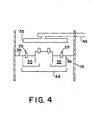
- FIG. 4 is an elevation view of the mixing system of the present invention according to a second embodiment in which a secondary swirl chamber is employed.
- FIG. 1 shows, in simplified form, a hydroprocessing reactor column in accordance with the present invention.
- the general configuration of the reactor is conventional, as are details such as the supports for the grids and distributor plates which are not shown for purposes of clarity.
- the reactor column 15 is formed as a generally cylindrical chamber having an outer wall 16.
- a reactor inlet 17 and a reactor outlet 18 are provided for introducing and discharging fluids from the reactor column 15.
- the reactor column 15 further comprises one or more catalyst beds 20 positioned along the longitudinal axis of the reactor column 15. )
- Each of the catalyst beds 20 contains catalyst material 21 which is preferably supported below by a catalyst support grid 22.
- the catalyst support grid 22, together with the outer wall 16, provides direct support for the catalyst material 21.
- the catalyst support grid 22 may provide indirect support for the catalyst 21 by retaining one or more layers of a larger supporting solid or solids which in turn support the catalyst 21.
- a distribution tray 23, for facilitating even distribution of fluids over the catalyst 21, is preferably provided above the catalyst material 21.
- the catalyst support grids 22 and the distribution trays 23 comprise meshed or perforated portions having openings sufficiently large to allow fluids to pass therethrough.
- the openings in the catalyst support grids 22 are sufficiently small so as to prevent the catalyst 21 from passing through.
- the openings in the distribution trays 23, and any flow devices which may be associated with the openings in the distribution trays 23, should be sized and spaced such that fluids deposited onto the distribution tray 23 are generally forced to spread substantially over the distribution tray 23 before passing through distribution tray 23.
- interbed mixing zones function, in part, to provide a homogeneous mixture of reactants to the catalyst beds 20. Additionally, the interbed mixing zones provide a convenient position for introducing quench fluids and/or supplemental reactants into reactor column 15.
- the embodiment shown in Figure 1 contains three catalyst beds 20 and two interbed mixing zones, it will be appreciated by those skilled in the art that the reactor in accordance with the present invention may contain more or less than three catalyst beds and more or less than two interbed mixing zones.
- a mixing system is positioned within at least one of the interbed mixing zones.
- the mixing system comprises a collection tray 26 which extends generally perpendicular to a longitudinal axis of reactor column 15. Collection tray 26 spans substantially across the entire diameter of reactor column 15 so as to divide the interbed mixing zone into an upper and a lower region. Accordingly, collection tray 26 collects fluids passing through the catalyst bed 20 which is positioned above collection tray 26.
- each collection tray 26 comprises two passageways 29 formed as spillways.
- Each of the spillways is formed as an opening 30 within the collection tray 26.
- a first conduit 31 is formed above the opening 30 for directing fluids through opening 30 and a second conduit 32 is formed beneath opening 30 for directing fluids that have passed through opening 30 away from opening 30.
- the passageways may comprise open-ended tubes passing through collection tray 26.
- Mixing chamber 35 is positioned below collection tray 26 to receive fluids which pass through passageways 29.
- the mixing chamber comprises a cylindrical wall 36 attached to, and extending generally perpendicular away from a lower surface of collection tray 26.
- Mixing chamber 35 further comprises floor 37, extending generally horizontally from cylindrical wall 36 upon which fluid can collect.
- Weir 40 is positioned generally peripherally at the end of floor 37 as a retaining wall extending perpendicularly and upwardly from floor 37 of mixing chamber 35. Fluids must therefore flow over weir 40 prior to exiting mixing chamber 35. Accordingly, weir 40 functions to retain fluid on the floor 37 of mixing chamber 35 until the level of fluid on floor 37 is about the same as, or higher than the height of weir 40.
- Flash pan 44 is optionally positioned within the interbed mixing zone below mixing chamber 35. Flash pan 44 comprises a floor with a retaining wall extending substantially vertically upward about the perimeter of the floor. Flash pan 44 also optionally comprises openings or upstanding pipes to convey fluid through the floor of flash pan 44. Flash pan 44 may be provided to receive fluids as they are discharged from mixing chamber 35 so as to evenly distribute the fluids over the surface of distribution tray 23.
- one or more quench feed lines 46 extend through the wall 16 of reactor column 15 into one or more quench injectors 55 within the interbed mixing zones.
- Injectors 55 enable a fluid to be injected into one or more of the interbed mixing zones.
- Quench feed lines 46 may also enter through the top or bottom head of reactor column 15 and pass through catalyst beds 20 and distribution trays 23 to arrive at an injector 55 within the interbed mixing zone.
- hydrogen may be injected as both a quench fluid and as a reactant.
- the quench fluid may be a gas, a liquid or a mixture of gas and liquid.
- Injectors 55 should provide a uniform, initial distribution of the quench fluid as further described herein.
- FIG. 1 further shows a baffle 42 within mixing chamber 35.
- baffle 42 facilitates the mixing of fluids within mixing chamber 35.
- baffle 42 extends perpendicularly and downwardly from the bottom of collection tray 26.
- quench fluid mixing is significantly improved by a novel means of quench introduction within reactor column 15.
- quench injection is configured so as to cause a rotational current on collection tray 26. This, in turn, provides fluid mixing which is highly complementary to the rotational flows induced within the mixing chamber 35 below collection tray 26.
- conduit 31 is one such structure on collection tray 26 that tends to cause rotational fluid flow as fluid passes through the opening 30 in collection tray 26 and into the mixing chamber 35.
- Quench fluid is provided to reactor 15 via quench fluid inlet line 46.
- Quench fluid inlet line 46 is connected with quench injector ring 55 so that quench fluid flows from inlet line 46 directly into quench injector ring 55.
- Quench injector ring 55 contains a number of quench outlets 95 through which quench fluid may exit quench injector ring 55 and enter reactor 15 above collection tray 26.
- quench outlets 95 comprise a plurality of small pipes leading out the top of quench injector ring 55, each pipe having a 90-degree bend from vertical to horizontal and a short straight length (still as pipe) to direct the flow in a swirl.
- quench injector ring 55 includes twenty pipes evenly spaced around quench injector ring 55.
- the individual quench flows be directed horizontally within the reactor as opposed to in a direction which is not parallel to the plane of quench injector ring 55. Angles from 0 to 30 degrees with respect to such plane will allow significant rotational momentum to be generated. Angles exceeding 30 degrees with respect to such plane are less desirable because a significant fraction of the quench fluid momentum is not imparted as an angular momentum to the fluid on and above the collection tray 26, as well as due to risk of unfavorable impingement of the quench jets on the catalyst support grid, collection tray, and/or other internal member(s).
- the injected quench fluid velocity should be as high as practical to induce the most substantial current possible above the collection tray, while not exceeding relevant limits designed to avoid quench injector wear, jet impingement on internal surfaces, vibration or other detrimental mechanical phenomena.
- the swirl flow induced by the quench injectors favorably complements the swirl entrance flow to the principal mixing chamber.
- the swirl entrances are the spillways leading into the principal mixing chamber.
- the swirl flow induced by the quench injectors also favorably complements the entrance flow to the secondary swirl chamber or device, provided these additional swirl devices produce rotation in the same direction as that in the principal mixing chamber.
- the invention would give a disproportionate improvement in mixing efficiency when applied in quench zones having multiple swirl devices.
- one or more quench injection points are selected such that (i) the accompanying lateral velocities of process fluids in the region are low, (ii) sufficient volume is available for the quench fluid to mix with the process fluids, and (iii) the quench is introduced with a velocity which is principally opposed to that of the process fluid transverse velocity.
- the best location for the associated injector(s) can be determined in accordance with the teachings herein.
- the openings in the collection tray 26 are at or near the center of reactor 15.
- process fluids exiting downward through the catalyst support grid must travel generally horizontally along or above collection tray 26 toward the openings in collection tray 26.
- the space above the collection tray 26 is mostly empty volume free of obstructions, then the flow paths will proceed directly toward the openings.
- baffles are present on the upper surface of collection tray 26, the flow paths will proceed toward the openings by a more indirect route defined by the baffles.
- quench is injected where the process fluids are traveling at a low relative velocity and such that the quench is injected in a direction opposite that of the process fluid flow. In general, this dictates that quench be injected nearer to the wall 16 of reactor 15 and in an outward direction. However, it is also preferable according to the second criteria of that invention to ensure adequate mixing space between the injection point(s) and the reactor wall 16 in order to maximize mixing efficiency.
- quench injection ring 55 is in a region of low transverse velocity but still leaves mixing space between itself and the reactor outer wall 16, and injects somewhat opposed to the transverse (radial inward) process flow.
- quench injection ring 55 is in a region of low transverse velocity but still leaves mixing space between itself and the reactor outer wall 16, and injects somewhat opposed to the transverse (radial inward) process flow.
- quench injection ring 55 is in a region of low transverse velocity but still leaves mixing space between itself and the reactor outer wall 16, and injects somewhat opposed to the transverse (radial inward) process flow.
- quench injection ring 55 is in a region of low transverse velocity but still leaves mixing space between itself and the reactor outer wall 16, and injects somewhat opposed to the transverse (radial inward) process flow.
- the process for determining the optimal location for injection points and providing optimal quench flow patterns may also be applied to interbed systems wherein substantially vertical baffles on the upper surface of collection tray 26 prevent process fluid from following a direct radial path to the openings in collection tray 26, provided these baffles do not extend so high as to preclude a coherent reactor-wide current from being induced.
- substantially vertical baffles on the upper surface of collection tray 26 prevent process fluid from following a direct radial path to the openings in collection tray 26, provided these baffles do not extend so high as to preclude a coherent reactor-wide current from being induced.
- fluid is forced to follow a longer path to a central opening, thereby increasing mean residence time on collection tray 26. As a result, extended contact between the fluids from different regions of reactor 15 is attained.
- the teachings of the present invention may be employed to design a quench injection means in the intervening space which creates a swirl flow in the same direction as the flow induced by the spiral baffle, enhancing the mixing efficiency of the quench zone.
Landscapes
- Chemical & Material Sciences (AREA)
- Organic Chemistry (AREA)
- Chemical Kinetics & Catalysis (AREA)
- Oil, Petroleum & Natural Gas (AREA)
- Engineering & Computer Science (AREA)
- General Chemical & Material Sciences (AREA)
- Devices And Processes Conducted In The Presence Of Fluids And Solid Particles (AREA)
Applications Claiming Priority (2)
| Application Number | Priority Date | Filing Date | Title |
|---|---|---|---|
| US439960 | 2003-05-16 | ||
| US10/439,960 US7074372B2 (en) | 2003-05-16 | 2003-05-16 | Multiphase mixing device with improved quench injection for inducing rotational flow |
Publications (2)
| Publication Number | Publication Date |
|---|---|
| EP1477221A1 true EP1477221A1 (de) | 2004-11-17 |
| EP1477221B1 EP1477221B1 (de) | 2008-04-16 |
Family
ID=33029824
Family Applications (1)
| Application Number | Title | Priority Date | Filing Date |
|---|---|---|---|
| EP04011353A Expired - Lifetime EP1477221B1 (de) | 2003-05-16 | 2004-05-13 | Mehrphasenmischvorrichtung mit verbessertem Quenchinjektor zur Erzeugung einer Drehströmung |
Country Status (6)
| Country | Link |
|---|---|
| US (1) | US7074372B2 (de) |
| EP (1) | EP1477221B1 (de) |
| JP (1) | JP2004337853A (de) |
| CA (1) | CA2467325A1 (de) |
| DE (1) | DE602004013070T2 (de) |
| SG (1) | SG115667A1 (de) |
Cited By (8)
| Publication number | Priority date | Publication date | Assignee | Title |
|---|---|---|---|---|
| WO2007127127A1 (en) * | 2006-04-25 | 2007-11-08 | Exxonmobil Research And Engineering Company | Dual gas-liquid spargers for catalytic processing units |
| US7601310B2 (en) * | 2005-05-13 | 2009-10-13 | Haldor Topsoe A/S | Distributor system for downflow reactors |
| CN101912764A (zh) * | 2010-08-19 | 2010-12-15 | 陕西雷光环保科技有限公司 | 无动力旋流反应方法及反应器 |
| WO2012098293A1 (en) * | 2011-01-18 | 2012-07-26 | Neste Oil Oyj | Method and arrangement for feeding heat-sensitive materials to fixed-bed reactors |
| WO2014056935A1 (en) | 2012-10-10 | 2014-04-17 | Shell Internationale Research Maatschappij B.V. | Multiple-bed downflow reactor comprising a mixing device, use of said reactor, as well as mixing method |
| CN103785332A (zh) * | 2012-11-03 | 2014-05-14 | 中国石油化工股份有限公司 | 一种两相加氢反应器及应用 |
| CN106350109A (zh) * | 2016-09-24 | 2017-01-25 | 中国石油大学(华东) | 一种催化裂化多级反应分离一体化旋流装置 |
| WO2024126367A1 (en) * | 2022-12-13 | 2024-06-20 | Topsoe A/S | Multiple-bed catalytic reactor comprising a distribution device |
Families Citing this family (23)
| Publication number | Priority date | Publication date | Assignee | Title |
|---|---|---|---|---|
| KR100833826B1 (ko) * | 2000-12-11 | 2008-06-02 | 쉘 인터내셔날 리서치 마챠피즈 비.브이. | 액체 혼합용 교반실을 갖는 혼합 장치 |
| US7161960B2 (en) * | 2002-03-26 | 2007-01-09 | Nokia Corporation | Apparatus, and associated method, for forming, and operating upon, multiple-checksum-protected data packet |
| US7174722B2 (en) * | 2005-01-24 | 2007-02-13 | Delphi Technologies, Inc. | Stirling cycle beverage cooler |
| US8177198B2 (en) * | 2008-06-26 | 2012-05-15 | Uop Llc | Quench zone design using spray nozzles |
| US8181942B2 (en) * | 2008-06-26 | 2012-05-22 | Uop Llc | Liquid redistribution device for multibed reactors |
| US8921627B2 (en) * | 2008-12-12 | 2014-12-30 | Uop Llc | Production of diesel fuel from biorenewable feedstocks using non-flashing quench liquid |
| KR101292455B1 (ko) * | 2009-12-01 | 2013-07-31 | 에스케이이노베이션 주식회사 | 반응기용 급랭 장치 |
| US8372354B2 (en) | 2010-07-19 | 2013-02-12 | Chevron U.S.A. Inc. | Multiphase contact and distribution apparatus for hydroprocessing |
| US8202498B2 (en) * | 2010-07-19 | 2012-06-19 | Chevron U.S.A. Inc. | Multiphase contact and distribution apparatus for hydroprocessing |
| US8900443B2 (en) | 2011-04-07 | 2014-12-02 | Uop Llc | Method for multi-staged hydroprocessing using quench liquid |
| WO2013092831A1 (en) * | 2011-12-22 | 2013-06-27 | Shell Internationale Research Maatschappij B.V. | Distributor device for a multiple-bed downflow reactor |
| US9630159B2 (en) | 2011-12-22 | 2017-04-25 | Shell Oil Company | Distributor device for a multiple-bed downflow reactor |
| KR102012629B1 (ko) * | 2011-12-22 | 2019-10-21 | 쉘 인터내셔날 리써취 마트샤피지 비.브이. | 다층 하향류 반응기용 분배장치 |
| FR2989006B1 (fr) * | 2012-04-04 | 2016-11-18 | Ifp Energies Now | Reacteur catalytique avec dispositif de trempe muni d'une injection tangentielle d'un fluide de trempe |
| CN103446957B (zh) * | 2012-05-28 | 2015-08-19 | 中国石油天然气股份有限公司 | 一种冷氢推进的旋流式冷氢箱 |
| CN105188902B (zh) * | 2013-02-05 | 2018-09-25 | 托普索公司 | 具有混合设备的多床式反应器 |
| US9211516B2 (en) * | 2013-06-28 | 2015-12-15 | Uop Llc | Fluid distribution device for multibed reactors |
| US10589244B1 (en) * | 2019-02-07 | 2020-03-17 | Uop Llc | Hydroprocessing reactor internals having reduced height |
| US11298670B2 (en) | 2020-04-24 | 2022-04-12 | Uop Llc | Compact quench zone reactor internals |
| US11207650B1 (en) | 2020-09-30 | 2021-12-28 | Uop Llc | Hydroprocessing reactor internals having reduced height |
| CN115845655B (zh) * | 2021-09-18 | 2024-11-08 | 中国石油天然气集团有限公司 | 一种流体混合装置、模拟移动床、相关系统及其应用 |
| CN114405413B (zh) * | 2021-12-09 | 2023-04-28 | 西安航天华威化工生物工程有限公司 | 一种正丁烷法生产顺酐的反应装置 |
| CN117085503B (zh) * | 2023-10-19 | 2024-01-23 | 汇舸(南通)环保设备有限公司 | 一种船舶尾气净化用的脱硫处理智能喷淋装置 |
Citations (3)
| Publication number | Priority date | Publication date | Assignee | Title |
|---|---|---|---|---|
| US3787189A (en) * | 1971-12-17 | 1974-01-22 | Standard Oil Co | Apparatus for mixing fluids in a vessel between beds of solids |
| EP0462753A1 (de) * | 1990-06-18 | 1991-12-27 | Exxon Research And Engineering Company | Zwischengebietmischeinrichtung |
| US20020172632A1 (en) * | 2001-04-02 | 2002-11-21 | Tai-Sheng Chou | Quench box for a multi-bed, mixed-phase cocurrent downflow fixed-bed reactor |
Family Cites Families (15)
| Publication number | Priority date | Publication date | Assignee | Title |
|---|---|---|---|---|
| US4836989A (en) * | 1987-07-02 | 1989-06-06 | Mobil Oil Corporation | Distribution system for downflow reactors |
| US4960571A (en) * | 1988-12-14 | 1990-10-02 | Exxon Research And Engineering Company | Quench assembly design |
| US5025831A (en) * | 1990-08-24 | 1991-06-25 | Exxon Research & Engineering Company | Compact radial flow distributor |
| JP3088736B2 (ja) * | 1990-08-24 | 2000-09-18 | エクソン リサーチ アンド エンヂニアリング コムパニー | 冷却組立体 |
| US5403560A (en) * | 1993-05-13 | 1995-04-04 | Texaco Inc. | Fluids mixing and distributing apparatus |
| DK171572B1 (da) | 1994-01-12 | 1997-01-20 | Topsoe Haldor As | Fremgangsmåde og indretning til blanding af gasser |
| US5462719A (en) * | 1994-06-08 | 1995-10-31 | Atlantic Richfield Company | Method and apparatus for mixing and distributing fluids in a reactor |
| EP0716881B1 (de) | 1994-08-23 | 1998-06-03 | Shell Internationale Researchmaatschappij B.V. | Verteilervorrichtung für abwärtsfliessende mehrstufige Reaktoren |
| US5635145A (en) * | 1994-08-23 | 1997-06-03 | Shell Oil Company | Multi-bed downflow reactor |
| US5690896A (en) * | 1995-05-05 | 1997-11-25 | Chevron U.S.A. Inc. | Distributor assembly for multi-bed down-flow catalytic reactors |
| US5837208A (en) * | 1996-06-12 | 1998-11-17 | Uop | Hydroprocessing reactor mixer/distributor |
| CN1243609C (zh) * | 1997-03-14 | 2006-03-01 | 日石三菱株式会社 | 一种混合装置 |
| US5935413A (en) * | 1997-12-03 | 1999-08-10 | Mobil Oil Corporation | Interbed gas-liquid mixing system for cocurrent downflow reactors |
| US6183702B1 (en) * | 1998-12-21 | 2001-02-06 | Chevron U.S.A. Inc. | Fluid distributor assembly for a multi-bed, downflow catalytic reactor |
| KR100833826B1 (ko) * | 2000-12-11 | 2008-06-02 | 쉘 인터내셔날 리서치 마챠피즈 비.브이. | 액체 혼합용 교반실을 갖는 혼합 장치 |
-
2003
- 2003-05-16 US US10/439,960 patent/US7074372B2/en not_active Expired - Fee Related
-
2004
- 2004-04-07 SG SG200401967A patent/SG115667A1/en unknown
- 2004-05-12 JP JP2004142192A patent/JP2004337853A/ja active Pending
- 2004-05-13 EP EP04011353A patent/EP1477221B1/de not_active Expired - Lifetime
- 2004-05-13 DE DE602004013070T patent/DE602004013070T2/de not_active Expired - Fee Related
- 2004-05-14 CA CA002467325A patent/CA2467325A1/en not_active Abandoned
Patent Citations (3)
| Publication number | Priority date | Publication date | Assignee | Title |
|---|---|---|---|---|
| US3787189A (en) * | 1971-12-17 | 1974-01-22 | Standard Oil Co | Apparatus for mixing fluids in a vessel between beds of solids |
| EP0462753A1 (de) * | 1990-06-18 | 1991-12-27 | Exxon Research And Engineering Company | Zwischengebietmischeinrichtung |
| US20020172632A1 (en) * | 2001-04-02 | 2002-11-21 | Tai-Sheng Chou | Quench box for a multi-bed, mixed-phase cocurrent downflow fixed-bed reactor |
Cited By (14)
| Publication number | Priority date | Publication date | Assignee | Title |
|---|---|---|---|---|
| US7601310B2 (en) * | 2005-05-13 | 2009-10-13 | Haldor Topsoe A/S | Distributor system for downflow reactors |
| WO2007127127A1 (en) * | 2006-04-25 | 2007-11-08 | Exxonmobil Research And Engineering Company | Dual gas-liquid spargers for catalytic processing units |
| CN101912764B (zh) * | 2010-08-19 | 2013-02-06 | 陕西雷光环保科技有限公司 | 无动力旋流反应方法及反应器 |
| CN101912764A (zh) * | 2010-08-19 | 2010-12-15 | 陕西雷光环保科技有限公司 | 无动力旋流反应方法及反应器 |
| US9352292B2 (en) | 2011-01-18 | 2016-05-31 | Neste Oyj | Method and arrangement for feeding heat-sensitive materials to fixed-bed reactors |
| WO2012098293A1 (en) * | 2011-01-18 | 2012-07-26 | Neste Oil Oyj | Method and arrangement for feeding heat-sensitive materials to fixed-bed reactors |
| WO2014056935A1 (en) | 2012-10-10 | 2014-04-17 | Shell Internationale Research Maatschappij B.V. | Multiple-bed downflow reactor comprising a mixing device, use of said reactor, as well as mixing method |
| KR20150067330A (ko) * | 2012-10-10 | 2015-06-17 | 쉘 인터내셔날 리써취 마트샤피지 비.브이. | 혼합 디바이스를 포함하는 다층 하향류 반응기, 상기 반응기의 용도, 및 혼합 방법 |
| US10076736B2 (en) | 2012-10-10 | 2018-09-18 | Shell Oil Company | Multiple-bed downflow reactor comprising a mixing device, use of said reactor, as well as mixing method |
| CN103785332A (zh) * | 2012-11-03 | 2014-05-14 | 中国石油化工股份有限公司 | 一种两相加氢反应器及应用 |
| CN103785332B (zh) * | 2012-11-03 | 2016-04-13 | 中国石油化工股份有限公司 | 一种两相加氢反应器及应用 |
| CN106350109A (zh) * | 2016-09-24 | 2017-01-25 | 中国石油大学(华东) | 一种催化裂化多级反应分离一体化旋流装置 |
| CN106350109B (zh) * | 2016-09-24 | 2018-03-23 | 中国石油大学(华东) | 一种催化裂化多级反应分离一体化旋流装置 |
| WO2024126367A1 (en) * | 2022-12-13 | 2024-06-20 | Topsoe A/S | Multiple-bed catalytic reactor comprising a distribution device |
Also Published As
| Publication number | Publication date |
|---|---|
| US7074372B2 (en) | 2006-07-11 |
| DE602004013070D1 (de) | 2008-05-29 |
| DE602004013070T2 (de) | 2009-07-16 |
| EP1477221B1 (de) | 2008-04-16 |
| CA2467325A1 (en) | 2004-11-16 |
| US20040234434A1 (en) | 2004-11-25 |
| JP2004337853A (ja) | 2004-12-02 |
| SG115667A1 (en) | 2005-10-28 |
Similar Documents
| Publication | Publication Date | Title |
|---|---|---|
| US7074372B2 (en) | Multiphase mixing device with improved quench injection for inducing rotational flow | |
| US7052654B2 (en) | Multiphase mixing device with staged gas introduction | |
| US9403139B2 (en) | Mixing device with tangential inlets for two-phase concurrent vessels | |
| EP2435172B1 (de) | Mischvorrichtung für einen katalytischen abwärtsflussreaktor | |
| JP2859670B2 (ja) | 下降流反応器のための分散系 | |
| AU699855B2 (en) | Distributor device for multiple-bed downflow reactors | |
| US6338828B1 (en) | Reactor distribution apparatus and quench zone mixing apparatus | |
| US7074371B2 (en) | Multiphase mixing device with improved quench injection | |
| US7601310B2 (en) | Distributor system for downflow reactors | |
| US7045103B2 (en) | Multiphase mixing device with baffles | |
| US7506861B2 (en) | Distribution device for two-phase concurrent downflow vessels | |
| KR20000016285A (ko) | 반응기 분배장치 및 급랭존 혼합장치_ | |
| CA2595478C (en) | Distribution device for two-phase concurrent downflow vessels | |
| EP3658271B1 (de) | Vorrichtung zur flüssigkeitskontaktierung in einem abstromgefäss | |
| EP3658270B1 (de) | Vorrichtung zur fluidkontaktierung in einem ablaufbehälter | |
| EP0716881B1 (de) | Verteilervorrichtung für abwärtsfliessende mehrstufige Reaktoren | |
| EP3658267B1 (de) | Verfahren zur fluidkontaktierung in einem abwärtsflussbehälter | |
| CN111344056B (zh) | 用于在下流式容器中进行流体接触的方法和设备 |
Legal Events
| Date | Code | Title | Description |
|---|---|---|---|
| PUAI | Public reference made under article 153(3) epc to a published international application that has entered the european phase |
Free format text: ORIGINAL CODE: 0009012 |
|
| 17P | Request for examination filed |
Effective date: 20040513 |
|
| AK | Designated contracting states |
Kind code of ref document: A1 Designated state(s): AT BE BG CH CY CZ DE DK EE ES FI FR GB GR HU IE IT LI LU MC NL PL PT RO SE SI SK TR |
|
| AX | Request for extension of the european patent |
Extension state: AL HR LT LV MK |
|
| AKX | Designation fees paid |
Designated state(s): BE DE FR GB IT NL |
|
| 17Q | First examination report despatched |
Effective date: 20060802 |
|
| 17Q | First examination report despatched |
Effective date: 20060802 |
|
| GRAP | Despatch of communication of intention to grant a patent |
Free format text: ORIGINAL CODE: EPIDOSNIGR1 |
|
| GRAS | Grant fee paid |
Free format text: ORIGINAL CODE: EPIDOSNIGR3 |
|
| GRAA | (expected) grant |
Free format text: ORIGINAL CODE: 0009210 |
|
| AK | Designated contracting states |
Kind code of ref document: B1 Designated state(s): BE DE FR GB IT NL |
|
| REF | Corresponds to: |
Ref document number: 602004013070 Country of ref document: DE Date of ref document: 20080529 Kind code of ref document: P |
|
| ET | Fr: translation filed | ||
| PLBE | No opposition filed within time limit |
Free format text: ORIGINAL CODE: 0009261 |
|
| STAA | Information on the status of an ep patent application or granted ep patent |
Free format text: STATUS: NO OPPOSITION FILED WITHIN TIME LIMIT |
|
| 26N | No opposition filed |
Effective date: 20090119 |
|
| PGFP | Annual fee paid to national office [announced via postgrant information from national office to epo] |
Ref country code: NL Payment date: 20090527 Year of fee payment: 6 |
|
| PGFP | Annual fee paid to national office [announced via postgrant information from national office to epo] |
Ref country code: DE Payment date: 20090529 Year of fee payment: 6 Ref country code: FR Payment date: 20090507 Year of fee payment: 6 Ref country code: IT Payment date: 20090519 Year of fee payment: 6 |
|
| PGFP | Annual fee paid to national office [announced via postgrant information from national office to epo] |
Ref country code: BE Payment date: 20090619 Year of fee payment: 6 |
|
| PGFP | Annual fee paid to national office [announced via postgrant information from national office to epo] |
Ref country code: GB Payment date: 20090407 Year of fee payment: 6 |
|
| BERE | Be: lapsed |
Owner name: EXXONMOBIL RESEARCH AND ENGINEERING CY Effective date: 20100531 |
|
| REG | Reference to a national code |
Ref country code: NL Ref legal event code: V1 Effective date: 20101201 |
|
| GBPC | Gb: european patent ceased through non-payment of renewal fee |
Effective date: 20100513 |
|
| REG | Reference to a national code |
Ref country code: FR Ref legal event code: ST Effective date: 20110131 |
|
| PG25 | Lapsed in a contracting state [announced via postgrant information from national office to epo] |
Ref country code: BE Free format text: LAPSE BECAUSE OF NON-PAYMENT OF DUE FEES Effective date: 20100531 Ref country code: NL Free format text: LAPSE BECAUSE OF NON-PAYMENT OF DUE FEES Effective date: 20101201 Ref country code: IT Free format text: LAPSE BECAUSE OF NON-PAYMENT OF DUE FEES Effective date: 20100513 |
|
| PG25 | Lapsed in a contracting state [announced via postgrant information from national office to epo] |
Ref country code: DE Free format text: LAPSE BECAUSE OF NON-PAYMENT OF DUE FEES Effective date: 20101201 |
|
| PG25 | Lapsed in a contracting state [announced via postgrant information from national office to epo] |
Ref country code: FR Free format text: LAPSE BECAUSE OF NON-PAYMENT OF DUE FEES Effective date: 20100531 |
|
| PG25 | Lapsed in a contracting state [announced via postgrant information from national office to epo] |
Ref country code: GB Free format text: LAPSE BECAUSE OF NON-PAYMENT OF DUE FEES Effective date: 20100513 |