EP1477131A2 - Protective elongated sleeve for stent systems - Google Patents
Protective elongated sleeve for stent systems Download PDFInfo
- Publication number
- EP1477131A2 EP1477131A2 EP04010120A EP04010120A EP1477131A2 EP 1477131 A2 EP1477131 A2 EP 1477131A2 EP 04010120 A EP04010120 A EP 04010120A EP 04010120 A EP04010120 A EP 04010120A EP 1477131 A2 EP1477131 A2 EP 1477131A2
- Authority
- EP
- European Patent Office
- Prior art keywords
- sleeve
- stent
- inner diameter
- outer diameter
- catheter
- Prior art date
- Legal status (The legal status is an assumption and is not a legal conclusion. Google has not performed a legal analysis and makes no representation as to the accuracy of the status listed.)
- Granted
Links
Images




Classifications
-
- A—HUMAN NECESSITIES
- A61—MEDICAL OR VETERINARY SCIENCE; HYGIENE
- A61F—FILTERS IMPLANTABLE INTO BLOOD VESSELS; PROSTHESES; DEVICES PROVIDING PATENCY TO, OR PREVENTING COLLAPSING OF, TUBULAR STRUCTURES OF THE BODY, e.g. STENTS; ORTHOPAEDIC, NURSING OR CONTRACEPTIVE DEVICES; FOMENTATION; TREATMENT OR PROTECTION OF EYES OR EARS; BANDAGES, DRESSINGS OR ABSORBENT PADS; FIRST-AID KITS
- A61F2/00—Filters implantable into blood vessels; Prostheses, i.e. artificial substitutes or replacements for parts of the body; Appliances for connecting them with the body; Devices providing patency to, or preventing collapsing of, tubular structures of the body, e.g. stents
- A61F2/95—Instruments specially adapted for placement or removal of stents or stent-grafts
-
- A—HUMAN NECESSITIES
- A61—MEDICAL OR VETERINARY SCIENCE; HYGIENE
- A61F—FILTERS IMPLANTABLE INTO BLOOD VESSELS; PROSTHESES; DEVICES PROVIDING PATENCY TO, OR PREVENTING COLLAPSING OF, TUBULAR STRUCTURES OF THE BODY, e.g. STENTS; ORTHOPAEDIC, NURSING OR CONTRACEPTIVE DEVICES; FOMENTATION; TREATMENT OR PROTECTION OF EYES OR EARS; BANDAGES, DRESSINGS OR ABSORBENT PADS; FIRST-AID KITS
- A61F2/00—Filters implantable into blood vessels; Prostheses, i.e. artificial substitutes or replacements for parts of the body; Appliances for connecting them with the body; Devices providing patency to, or preventing collapsing of, tubular structures of the body, e.g. stents
- A61F2/95—Instruments specially adapted for placement or removal of stents or stent-grafts
- A61F2/958—Inflatable balloons for placing stents or stent-grafts
- A61F2002/9583—Means for holding the stent on the balloon, e.g. using protrusions, adhesives or an outer sleeve
-
- A—HUMAN NECESSITIES
- A61—MEDICAL OR VETERINARY SCIENCE; HYGIENE
- A61M—DEVICES FOR INTRODUCING MEDIA INTO, OR ONTO, THE BODY; DEVICES FOR TRANSDUCING BODY MEDIA OR FOR TAKING MEDIA FROM THE BODY; DEVICES FOR PRODUCING OR ENDING SLEEP OR STUPOR
- A61M25/00—Catheters; Hollow probes
- A61M25/01—Introducing, guiding, advancing, emplacing or holding catheters
- A61M2025/0183—Rapid exchange or monorail catheters
-
- A—HUMAN NECESSITIES
- A61—MEDICAL OR VETERINARY SCIENCE; HYGIENE
- A61M—DEVICES FOR INTRODUCING MEDIA INTO, OR ONTO, THE BODY; DEVICES FOR TRANSDUCING BODY MEDIA OR FOR TAKING MEDIA FROM THE BODY; DEVICES FOR PRODUCING OR ENDING SLEEP OR STUPOR
- A61M25/00—Catheters; Hollow probes
- A61M25/10—Balloon catheters
- A61M2025/1043—Balloon catheters with special features or adapted for special applications
- A61M2025/1056—Balloon catheters with special features or adapted for special applications having guide wire lumens outside the main shaft, i.e. the guide wire lumen is within or on the surface of the balloon
Definitions
- This invention relates generally to catheter deployment of drug-coated stents. More specifically, the invention relates to a protective elongated sleeve for stent systems.
- stents for treating vascular conditions are being coated with pharmaceutical drugs and protective materials for controlled time-delivery of the therapeutic agents.
- Medical research indicates a greater effectiveness of vascular stents when the stents are coated with pharmaceutical drugs that help prevent or treat medical conditions.
- These drugs may be released from a coating while in the body, delivering their patent effects at the site where they are most needed.
- the drugs may be mixed, for example, within drug-polymers or encased by polymeric coatings on the stents.
- Stent coatings with various families of drug polymer chemistries have been used to increase the effectiveness of stenting procedures and to control drug-elution properties.
- One aspect of the invention provides a system for treating a vascular condition comprising a catheter, a stent deployment assembly coupled to the catheter and a protective sleeve.
- the protective sleeve removably covers the stent deployment assembly and at least a portion of the catheter.
- the protective sleeve comprises a hollow tube and has a proximal outer diameter, a medial inner diameter, and a distal inner diameter.
- the distal inner diameter is sufficient to encircle an outer diameter of the stent deployment assembly, and the medial inner diameter is sufficient to encircle an outer diameter of the catheter, and wherein the distal inner diameter is open, wherein the protective sleeve is removed from covering the stent framework prior to deploying the stent.
- the protective sleeve for a drug-eluting stent as part of a stent deployment assembly.
- the protective sleeve removably covers the stent deployment assembly and at least a portion of the catheter.
- the protective sleeve comprises a hollow tube and has a proximal outer diameter, a medial inner diameter, and a distal inner diameter.
- the distal inner diameter is sufficient to encircle an outer diameter of the stent deployment assembly, and wherein the medial inner diameter is sufficient to encircle an outer diameter of the catheter, and wherein the distal inner diameter is open, and the protective sleeve is retracted from covering the stent framework prior to deploying the stent.
- a system for treating a vascular condition comprising a catheter and a stent deployment assembly coupled to the catheter; the stent deployment assembly comprising a stent including a stent framework and a drug-polymer coating on at least a portion of the stent framework.
- the system further comprises means for protecting a surface of the stent framework.
- FIG. 1 shows one embodiment of the stent assembly 100.
- Stent assembly 100 comprises a catheter 40, a protective sleeve 10, a y-arm port 60, and a stent 20.
- FIG. 1 shows the sleeve 10 partially disposed within a leg of a Y-arm port 60.
- Y-arm ports are well known to those of ordinary skill in the art.
- the sleeve 10 is longer than the length of the Y-arm.
- the stent includes a stent framework and may comprise a drug coating on at least a portion of the stent framework.
- the stent framework may comprise a polymeric base or a metallic base such as stainless steel, nitinol, tantalum, MP35N alloy, platinum, titanium, a suitable biocompatible alloy, a suitable biocompatible material, a suitable polymeric material, or a combination thereof.
- the polymeric base material may comprise any suitable polymer for biomedical stent applications, as is known in the art.
- the stent framework may comprise a dissolvable material, such that the stent framework dissolves while implanted in a vessel of a body.
- the drug coating may include or encapsulate one or more therapeutic agents.
- the drug coating may comprise one or more therapeutic agents dispersed within or encased by a polymeric coating, which are eluted from the coated stent with controlled time delivery after deployment of coated stent within a body.
- a therapeutic agent is capable of producing a beneficial effect against one or more conditions including coronary restenosis, cardiovascular restenosis, angiographic restenosis, arteriosclerosis, hyperplasia, and other diseases and conditions.
- the therapeutic agent can be selected to inhibit or prevent vascular restenosis, a condition corresponding to a narrowing or constriction of the diameter of the bodily lumen where the stent is placed.
- the drug coating may comprise, for example, an antirestenotic drug, an antisense agent, an antineoplastic agent, an antiproliferative agent, an antithrombogenic agent, an anticoagulant, an antiplatelet agent, an antibiotic, an anti-inflammatory agent, a steroid, a gene therapy agent, an organic drug, a pharmaceutical compound, a recombinant DNA product, a recombinant RNA product, a collagen, a collagenic derivative, a protein, a protein analog, a saccharide, a saccharide derivative, a bioactive agent, a pharmaceutical drug, a therapeutic substance, or combinations thereof.
- the elution rates of the therapeutic agents into the body and the tissue bed surrounding the stent framework are based on the constituency and thickness of drug-polymer coating, the nature and concentration of the therapeutic agents, the thickness and composition of cap coat, and other factors.
- Protective sleeve 10 is slidably disposed around catheter 40, and stent 20.
- sleeve 10 is fabricated of clear material to allow for viewing a stent 20 contained within the sleeve 10.
- the sleeve 10 may be fabricated of opaque material to aid in preventing degradation of the coating 30 from light.
- sleeve 10 may be fabricated of ultraviolet-filtering material for protection from UV radiation.
- the sleeve 10 may be made, for example, of Teflon or other suitable materials.
- sleeve 10 may be made from nylon, polyurethane, polyethylene terephthalate, polyethylene, polytetrafluoroethylene, expanded polytetrafluoroethylene, an elastane, a thermoplastic elastomer, a woven polymeric fabric, or an expandable polymeric sheet.
- Drug coating 30 may include one or more drugs, and may comprise a drug-polymer coating. Each drug may include a bioactive agent.
- the bioactive agent may be a pharmacologically active drug or bioactive compound.
- the bioactive agent may be eluted from the drug coating 30 when the stent 20 has been deployed in the body. Elution refers to the transfer of the bioactive agent out from drug coating 30. The elution rate is determined by the rate at which the bioactive agent is excreted from drug-polymer coating 30 into the body.
- the composition of the drug-polymer coating and the interdispersed drugs may control the elution rate of the bioactive agent.
- the phenoxy primer coating underlying drug coating 30 would tend not to be eluted, metabolized, or discarded by the body.
- the drug coating 30 may be subject to degradation during processing, packaging, sterilization, or storage of a drug-polymer coated stent.
- sterilization for example, oxidation of the drug or polymer may occur, resulting in hydrolytic damage, cleavage of the polymeric bonds, breakdown of the polymer and/or drug, or actual cracking or peeling of the drug-polymer coating.
- Temperature excursions of the in-process or processed stent 20 may incite delamination of all or a portion of the drug coating 30.
- the risks of degradation are increased because of the lack of a metallic structure.
- the present invention solves this problem through the use of a protective sleeve to reduce or prevent drug-polymer delamination.
- FIG. 2 illustrates stent assembly 200.
- Stent assembly 200 comprises a catheter 40, a protective sleeve 10, a y-arm port 60, and a stent 20.
- Stent 20 may comprise a drug coating 30.
- sleeve 10 protects stent 20 from manual handling as stent 20 may be threaded out of sleeve 10 by deploying catheter 40 in the direction of the target site (indicated by arrow).
- Catheter 40 may protrude distally beyond sleeve 10 thereby providing a means for manipulating stent 20 without handling the stent within sleeve 10.
- sleeve 10 When stent segment 20 is disposed within sleeve 10, sleeve 10 may be handled without handling stent segment 20. In FIG. 1, stent 20 is illustrated partially disposed within the protective sleeve; while in FIG. 2, stent 20 is illustrated not disposed within the protective sleeve 10. Stent segment 20 is therefore, less likely to be disturbed during storage, handling or sleeve placement. Furthermore, sleeve 10 may be handled without disturbing a coating 30 that may be dispersed on stent segment 20. Coating 30 is therefore, less likely to be disturbed during storage, sleeve placement and during lab handling. In embodiments where the stent 20 comprises a dissolvable material, protective sleeve 10 contributes to handling the stent with minimal contact with the actual stent 20.
- FIG. 2 shows the sleeve 10 disposed within the Y-arm port 60.
- the sleeve 10 will pass through the Y-arm port 60 and will protect the stent 20 until it is removed when the stent 20 is at the desired position.
- the outer diameter of sleeve 10 is greater than the inner diameter of an o-ring in the Y-arm, and will therefore not pass through the o-ring.
- FIG. 1 shows the sleeve 10 prior to entry into a leg of a Y-arm port 60.
- the sleeve 10 is longer than the length of the Y-arm.
- FIG. 2 also illustrates a guide wire 65. Guide wires are well known in the art as one method of guiding the stent to its target site.
- one or more therapeutic agents may be in contact with polymeric coatings on coated stent 20.
- the system 100 may help treat, for example, heart disease, various cardiovascular ailments, and other vascular conditions by using catheter-deployed endovascular stents that have tailored polymeric coatings for controlling the timed-release properties of interdispersed or encased therapeutic agents.
- Treatment of vascular conditions may include the prevention or correction of various ailments and deficiencies associated with the cardiovascular system, the cerebrovascular system, urinogenital systems, biliary conduits, abdominal passageways and other biological vessels within the body.
- y-arm 60 generally provides a port to a vessel.
- Other ports into a vessel are possible, and this invention is adaptable to work with any port into a vessel.
- Other embodiments, some of which are illustrated in FIGS 6, 7, and 8, do not use a y-arm port, but use other ports that are generally known in the art.
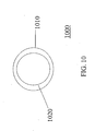
- FIG. 10 depicts a cross section of the sleeve at 1000.
- the outer diameter of the sleeve is depicted as 1010, and the inner diameter of the sleeve is depicted as 1020.
- the sleeve generally comprises a hollow tube, although the inner and outer diameter may vary along the length of the protective sleeve.
- the protective sleeve may comprise a lubricious covering, on the inner surface, the outer surface or both.
- a lubricious covering may cover at least a portion of outer surface 1010, inner surface 1020, or both inner surface 1010 and outer surface 1020.
- a lubricious coating may be positioned on at least a portion of an outer surface of the protective sleeve.
- the lubricious coating may comprise a material such as phosphorylcholine, a hydrophilic coating, or a lubricious film.
- Other portions of the system disclosed herein may also be coated with lubricious coating to minimize the coefficient of friction between the coated surface and structures surrounding the coated surface.
- a lubricious covering may be applied to the outer surface of the stent and the inner surface of the protective sleeve to ease removal of the protective sleeve at the target location.
- Patterns, stripes, and fractional coverage of the various surfaces with the lubricious coating may be used to control stent retention during delivery and deployment.
- the outer diameter of the protective sleeve will be determined by determining whether the protective sleeve will be delivered to the vasculature, or whether the protective sleeve should remain in the port to the vessel. In the first embodiment, the sleeve is allowed to pass through the o-ring, and in the second, the sleeve is not allowed to pass through the o-ring.
- the protective sleeve should have an inner diameter sized to allow free and unrestricted movement of the stent delivery assembly longitudinally, but with limited movement laterally.
- the inner diameter of the sleeve will comprise a lubricious coating to provide for easier removal of the sleeve from the underlying stent delivery assembly. It may also be optimal to construct different sections of the sleeve from different materials.
- the distal portion of the sleeve may comprise a material that has greater flexibility than the medial or proximal portion of the sleeve.
- the use of the catheter will be generally as used in the prior art.
- the system must also contain means to retract the sheath. Generally these means will be such that the sleeve may be pulled back, with an application of a retracting force at the proximal end of the sleeve.
- Such means are known in the art, and are in use for self-expanding stents. These means may include the use of wire or rod, or a tubular member. As these means are generally known in the art, the retraction means are not pictured in the figures.
- This invention is optimally used in conjunction with self-expanding stents, and the means for retracting the sleeve may be used in conjunction with the means for allowing the self-expanding stent to expand.
- a self-expanding stent In the use of a self-expanding stent, it is common that the stent be prevented from expanding at an undesired location with the use of a sheath. Upon reaching the desired deployment site, these self-expanding sheaths are removed.
- Some embodiments of the protective sleeve disclosed herein may be coupled to a self-expanding stent sheath, although this is not required to practice the invention. Thus, some embodiments may operably connect the retraction means for retaining means of a self-expanding stent with the means to retract the protective sleeve disclosed herein.
- the sleeve is easily adapted to a variety of catheter delivery systems.
- Example adaptations of the sleeve are depicted in FIG. 6 (Zipper delivery), FIG. 7 (Rapid Exchange delivery), and FIG. 8A/8B (over the wire).
- This invention may be used to protect self-expanding stents.
- FIG. 3 shows a side view of the protective sleeve 10 in one embodiment of the instant invention.
- Proximal end 305 tapers to the medial portion 350.
- Medial portion 350 tapers to the distal end 390.
- medial portion 350 has an inner diameter of .045 centimeters, and an outer diameter of .055 centimeters.
- the distal end 390 has an inner diameter of .071 centimeters, and an outer diameter of .0825 centimeters. These measurements are examples only, and any appropriate diameter may be used to practice the invention.
- the distal inner diameter will be sufficient to encircle an outer diameter of the catheter
- the medial inner diameter will be sufficient to encircle the stent deployment assembly
- the proximal inner diameter will be sufficient to encircle the catheter.
- FIG. 4 shows one embodiment of the instant invention.
- FIG. 4 illustrates stent assembly 400 as shipped.
- Stent assembly 400 comprises Y-arm 410, protective sleeve 420, and catheter 430.
- Stent assembly 400 is pictured with the sleeve 420 distal the Y-arm.
- Catheter 430 is shown surrounded by the sleeve 420.
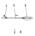
- FIG. 5 shows the same embodiment of the instant invention as FIG. 4, but with the sleeve 520 in a deployed position.
- Stent assembly 500 comprises Y-arm 510, protective sleeve 520, and catheter 530.
- Sleeve 520 is now distal the position illustrated in FIG. 4, and continues to surround catheter 530.
- the sleeve will comprise a guide wire notch, as is illustrated in greater detail below.
- FIG. 6 illustrates an embodiment of the instant invention wherein the sleeve 620 is adapted for use on a zipper delivery system.
- FIG. 6 shows stent assembly 600, comprising vessel port 610, toughy lock 609, protective sleeve 620, and catheter 630.
- FIG. 6A is a cross section of the sleeve 620 taken at line B-B.
- the sleeve 620 when adapted for use on a zipper delivery system, the sleeve 620 comprises an inner shaft 645 and an outer shaft 655. Both the inner shaft 645 and the outer shaft 655 comprise a gap 670 to allow passage of the zipper.
- the zipper extends longitudinally through gap 670. Referring back to FIG.
- toughy lock 609 comprises an o-ring (not shown).
- the o-ring will engage the outer diameter of the protective sleeve 620 and prevent the protective sleeve 620 from entering the vasculature.
- Catheter 630 extends longitudinally from the toughy lock 609, as is known in the art for zipper delivery systems. 610 is a port into a vessel that is not a y-arm.
- the system comprises a guide wire
- the protective sleeve comprises a guide wire notch.
- the guide wire extends longitudinally through the guide wire notch.
- the guide wire notch extends at least part of the distance from an outer surface of the protective sleeve through to the inner surface.
- the protective sleeve slides freely longitudinally along the guide wire riding in the guide wire notch, with substantially no lateral movement.
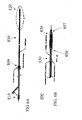
- FIG. 7 illustrates an embodiment of the instant invention for a monorail system.
- FIG. 7 shows stent assembly 700, comprising vessel port 710, hypotube 708, toughy lock 709, protective sleeve 720, and catheter 730.
- Catheter 730 extends longitudinally from the hypotube 708, through the toughy lock 709.
- Protective sleeve 720 is pictured at the distal end of the catheter.
- the close-up view of the protective sleeve 720 shows the sleeve 720 tapering up at the proximal end 756 of the protective sleeve, and tapering down at the distal end 757 of the protective sleeve.
- 710 illustrates a port into a vessel that is not a y-arm.
- the assembly 700 further includes a guidewire (not shown) and the protective sleeve 720 comprises a guidewire notch, wherein the assembly travels longitudinally along the guidewire disposed in the guidewire notch.
- FIGS. 8 and 8A illustrate an embodiment of the instant invention utilizing an over-the-wire (OTW) delivery system.
- OW systems are well known in the art.
- FIG. 8 shows stent assembly 800, comprising vessel port 810, toughy lock 809, protective sleeve 820, and catheter 830.
- FIG. 8A shows close-up view of the protective sleeve 820 shows the protective sleeve 820 tapering up at the proximal end 856 of the protective sleeve, and tapering down at the distal end 857 of the protective sleeve.
- FIG. 8 shows an embodiment of the invention wherein the sleeve travels along the catheter to the stent deployment area, and therefore, the protective sleeve 820 is pictured distal the vessel port 810.
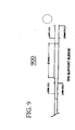
- FIG. 9 is a side view of a sleeve 900 in accordance with the instant invention.
- the proximal end of the sleeve is smaller than the medial and distal ends of the sleeve.
- the proximal end of the sleeve has an inner diameter of .045 centimeters, and an outer diameter of .055 centimeters.
- the medial portion and distal portion have an inner diameter of .071 centimeters and an outer diameter of .0825 centimeters.
- the medial and distal portions of the sleeve are 7.5 centimeters long as shown, but need only be longer than the Y-arm or other port into a vessel.
Landscapes
- Health & Medical Sciences (AREA)
- Engineering & Computer Science (AREA)
- Biomedical Technology (AREA)
- Cardiology (AREA)
- Oral & Maxillofacial Surgery (AREA)
- Transplantation (AREA)
- Heart & Thoracic Surgery (AREA)
- Vascular Medicine (AREA)
- Life Sciences & Earth Sciences (AREA)
- Animal Behavior & Ethology (AREA)
- General Health & Medical Sciences (AREA)
- Public Health (AREA)
- Veterinary Medicine (AREA)
- Media Introduction/Drainage Providing Device (AREA)
- Materials For Medical Uses (AREA)
Abstract
Description
Claims (18)
- A system for treating a vascular condition, comprising:wherein the distal inner diameter is sufficient to encircle an outer diameter of the stent deployment assembly, wherein the medial inner diameter is sufficient to encircle an outer diameter of the catheter, wherein the distal inner diameter is open, and wherein the protective sleeve is removed from covering the stent framework prior to deploying the stent.a catheter (40);a stent deployment assembly coupled to the catheter; the stent deployment assembly comprising a coated stent (20) including a stent framework and a drug coating (30) disposed on at least a portion of the stent framework; anda protective sleeve (10) removably covering the stent deployment assembly and at least a portion of the catheter, wherein said sleeve comprises a hollow tube having a proximal outer diameter, a medial inner diameter, and a distal inner diameter; and
- The system of claim 1 further comprising a port to a vessel, wherein the port (610) comprises a toughy lock (609), wherein the toughy lock further comprises an o-ring having an o-ring inner diameter, wherein the proximal outer diameter of the sleeve is greater than the o-ring inner diameter.
- The system of claim 1 further comprising a port (610) to a vessel, wherein the port comprises a toughy lock (609), wherein the toughy lock further comprises an o-ring that comprises an o-ring inner diameter, wherein the proximal outer diameter of the sleeve is less than the o-ring inner diameter.
- The system of any preceding claim further comprising a guide wire, and wherein the sleeve (10) further comprises a guide wire notch, wherein the guide wire extends longitudinally through the guide wire notch.
- The system of claim 4 wherein the guide wire notch extends at least part of the distance from an outer surface of the sleeve (10) through an inner surface of the sleeve.
- The system of any preceding claim wherein the sleeve (10) comprises a material selected from the group consisting of nylon, polyurethane, polyethylene terephthalate, polyethylene, polytetrafluoroethylene, expanded polytetrafluoroethylene, an elastane, a thermoplastic elastomer, a woven polymeric fabric, or an expandable polymeric sheet.
- The system of any preceding claim wherein the sleeve (10) comprises a material that dissolves while in a vasculature.
- The system of any preceding claim further comprising:a lubricious coating on at least a portion of a surface of the sleeve.
- The system of claim 8 wherein the lubricious coating comprises a material selected from the group consisting of phosphorylcholine, a hydrophilic coating, and a lubricious film.
- The system of any preceding claim wherein the sleeve (10) has a distal inner diameter of substantially .071 centimeters, a distal outer diameter of substantially .0825 centimeters, a medial inner diameter of .045 centimeters, and a medial outer diameter of .055 centimeters.
- A protective sleeve for a stent assembly, comprising:A hollow tube having a proximal outer diameter, a medial inner diameter, and a distal inner diameter, wherein the distal inner diameter is sufficient to encircle an outer diameter of the stent assembly, wherein the distal inner diameter is open, and wherein the sleeve retractably covers the stent deployment assembly.
- The sleeve of claim 11 wherein the sleeve (10) has an outer diameter that is greater than the inner diameter of an o-ring of a toughy lock, and wherein the sleeve can not pass the o-ring of the doughy lock during deployment of the stent assembly.
- The sleeve of claim 11 wherein the sleeve (10) has an outer diameter that is less than the inner diameter of an o-ring of a toughy lock (609), and wherein the sleeve passes the o-ring of the toughy lock during deployment, and wherein the sleeve is removed from the stent assembly at a site where the stent is to be deployed.
- The sleeve of claim 11, 12 or 13 wherein the sleeve (10) has a distal inner diameter of substantially .071 centimeters, a distal outer diameter of substantially .0825 centimeters, a medial inner diameter of .045 centimeters, and a medial outer diameter of .055 centimeters.
- The sleeve of any of claims 11 to 14, further comprising a lubricious coating on at least a portion of a surface of the sleeve (10).
- The sleeve of claim 15 wherein the lubricious coating comprises a material selected from the group consisting of phosphorylcholine, a hydrophilic coating, and a lubricious film.
- The system of any of claims 11 to 16 wherein the sleeve (10) comprises a material selected from the group consisting of nylon, polyurethane, polyethylene terephthalate, polyethylene, polytetrafluoroethylene, expanded polytetrafluoroethylene, an elastane, a thermoplastic elastomer, a woven polymeric fabric, an expandable polymeric sheet and a material that dissolves while in a vasculature.
- A system for treating a vascular condition, comprising:a catheter (40);a stent assembly coupled to the catheter; the stent assembly comprising a coated stent including a stent framework and a drug-polymer coating on at least a portion of the stent framework; andmeans for protecting a surface of the stent framework.
Applications Claiming Priority (2)
| Application Number | Priority Date | Filing Date | Title |
|---|---|---|---|
| US46693503P | 2003-05-01 | 2003-05-01 | |
| US466935P | 2003-05-01 |
Publications (3)
| Publication Number | Publication Date |
|---|---|
| EP1477131A2 true EP1477131A2 (en) | 2004-11-17 |
| EP1477131A3 EP1477131A3 (en) | 2007-05-09 |
| EP1477131B1 EP1477131B1 (en) | 2009-09-16 |
Family
ID=33030117
Family Applications (1)
| Application Number | Title | Priority Date | Filing Date |
|---|---|---|---|
| EP04010120A Expired - Lifetime EP1477131B1 (en) | 2003-05-01 | 2004-04-28 | Protective elongated sleeve for stent systems |
Country Status (3)
| Country | Link |
|---|---|
| US (1) | US20040267347A1 (en) |
| EP (1) | EP1477131B1 (en) |
| DE (1) | DE602004023151D1 (en) |
Families Citing this family (57)
| Publication number | Priority date | Publication date | Assignee | Title |
|---|---|---|---|---|
| DE10105592A1 (en) | 2001-02-06 | 2002-08-08 | Achim Goepferich | Placeholder for drug release in the frontal sinus |
| US8317816B2 (en) | 2002-09-30 | 2012-11-27 | Acclarent, Inc. | Balloon catheters and methods for treating paranasal sinuses |
| US8864787B2 (en) | 2004-04-21 | 2014-10-21 | Acclarent, Inc. | Ethmoidotomy system and implantable spacer devices having therapeutic substance delivery capability for treatment of paranasal sinusitis |
| US8146400B2 (en) | 2004-04-21 | 2012-04-03 | Acclarent, Inc. | Endoscopic methods and devices for transnasal procedures |
| US8894614B2 (en) | 2004-04-21 | 2014-11-25 | Acclarent, Inc. | Devices, systems and methods useable for treating frontal sinusitis |
| US7361168B2 (en) | 2004-04-21 | 2008-04-22 | Acclarent, Inc. | Implantable device and methods for delivering drugs and other substances to treat sinusitis and other disorders |
| US8932276B1 (en) | 2004-04-21 | 2015-01-13 | Acclarent, Inc. | Shapeable guide catheters and related methods |
| US8747389B2 (en) | 2004-04-21 | 2014-06-10 | Acclarent, Inc. | Systems for treating disorders of the ear, nose and throat |
| US20190314620A1 (en) | 2004-04-21 | 2019-10-17 | Acclarent, Inc. | Apparatus and methods for dilating and modifying ostia of paranasal sinuses and other intranasal or paranasal structures |
| US7419497B2 (en) | 2004-04-21 | 2008-09-02 | Acclarent, Inc. | Methods for treating ethmoid disease |
| US20070208252A1 (en) | 2004-04-21 | 2007-09-06 | Acclarent, Inc. | Systems and methods for performing image guided procedures within the ear, nose, throat and paranasal sinuses |
| US8764729B2 (en) | 2004-04-21 | 2014-07-01 | Acclarent, Inc. | Frontal sinus spacer |
| US9554691B2 (en) | 2004-04-21 | 2017-01-31 | Acclarent, Inc. | Endoscopic methods and devices for transnasal procedures |
| US9351750B2 (en) | 2004-04-21 | 2016-05-31 | Acclarent, Inc. | Devices and methods for treating maxillary sinus disease |
| US7803150B2 (en) | 2004-04-21 | 2010-09-28 | Acclarent, Inc. | Devices, systems and methods useable for treating sinusitis |
| US9101384B2 (en) | 2004-04-21 | 2015-08-11 | Acclarent, Inc. | Devices, systems and methods for diagnosing and treating sinusitis and other disorders of the ears, Nose and/or throat |
| US7410480B2 (en) | 2004-04-21 | 2008-08-12 | Acclarent, Inc. | Devices and methods for delivering therapeutic substances for the treatment of sinusitis and other disorders |
| US7462175B2 (en) | 2004-04-21 | 2008-12-09 | Acclarent, Inc. | Devices, systems and methods for treating disorders of the ear, nose and throat |
| US8702626B1 (en) | 2004-04-21 | 2014-04-22 | Acclarent, Inc. | Guidewires for performing image guided procedures |
| US20070167682A1 (en) | 2004-04-21 | 2007-07-19 | Acclarent, Inc. | Endoscopic methods and devices for transnasal procedures |
| US20060063973A1 (en) | 2004-04-21 | 2006-03-23 | Acclarent, Inc. | Methods and apparatus for treating disorders of the ear, nose and throat |
| US7654997B2 (en) | 2004-04-21 | 2010-02-02 | Acclarent, Inc. | Devices, systems and methods for diagnosing and treating sinusitus and other disorders of the ears, nose and/or throat |
| US20060004323A1 (en) | 2004-04-21 | 2006-01-05 | Exploramed Nc1, Inc. | Apparatus and methods for dilating and modifying ostia of paranasal sinuses and other intranasal or paranasal structures |
| US9399121B2 (en) | 2004-04-21 | 2016-07-26 | Acclarent, Inc. | Systems and methods for transnasal dilation of passageways in the ear, nose or throat |
| US7559925B2 (en) | 2006-09-15 | 2009-07-14 | Acclarent Inc. | Methods and devices for facilitating visualization in a surgical environment |
| US9089258B2 (en) | 2004-04-21 | 2015-07-28 | Acclarent, Inc. | Endoscopic methods and devices for transnasal procedures |
| US10188413B1 (en) | 2004-04-21 | 2019-01-29 | Acclarent, Inc. | Deflectable guide catheters and related methods |
| EP3556319A1 (en) | 2005-05-24 | 2019-10-23 | Inspire M.D Ltd. | Stent apparatuses for treatment via body lumens |
| US8043323B2 (en) | 2006-10-18 | 2011-10-25 | Inspiremd Ltd. | In vivo filter assembly |
| US8961586B2 (en) * | 2005-05-24 | 2015-02-24 | Inspiremd Ltd. | Bifurcated stent assemblies |
| US8951225B2 (en) | 2005-06-10 | 2015-02-10 | Acclarent, Inc. | Catheters with non-removable guide members useable for treatment of sinusitis |
| US8114113B2 (en) | 2005-09-23 | 2012-02-14 | Acclarent, Inc. | Multi-conduit balloon catheter |
| US8900620B2 (en) | 2005-10-13 | 2014-12-02 | DePuy Synthes Products, LLC | Drug-impregnated encasement |
| US8190389B2 (en) | 2006-05-17 | 2012-05-29 | Acclarent, Inc. | Adapter for attaching electromagnetic image guidance components to a medical device |
| US8034287B2 (en) * | 2006-06-01 | 2011-10-11 | Abbott Cardiovascular Systems Inc. | Radiation sterilization of medical devices |
| US9820688B2 (en) | 2006-09-15 | 2017-11-21 | Acclarent, Inc. | Sinus illumination lightwire device |
| WO2008047369A2 (en) | 2006-10-18 | 2008-04-24 | Inspiremd Ltd. | Knitted stent jackets |
| EP2088962B1 (en) | 2006-11-22 | 2017-10-11 | Inspiremd Ltd. | Optimized stent jacket |
| US8439687B1 (en) | 2006-12-29 | 2013-05-14 | Acclarent, Inc. | Apparatus and method for simulated insertion and positioning of guidewares and other interventional devices |
| US8118757B2 (en) | 2007-04-30 | 2012-02-21 | Acclarent, Inc. | Methods and devices for ostium measurement |
| US8485199B2 (en) | 2007-05-08 | 2013-07-16 | Acclarent, Inc. | Methods and devices for protecting nasal turbinate during surgery |
| US7959857B2 (en) | 2007-06-01 | 2011-06-14 | Abbott Cardiovascular Systems Inc. | Radiation sterilization of medical devices |
| US10206821B2 (en) | 2007-12-20 | 2019-02-19 | Acclarent, Inc. | Eustachian tube dilation balloon with ventilation path |
| US8182432B2 (en) | 2008-03-10 | 2012-05-22 | Acclarent, Inc. | Corewire design and construction for medical devices |
| ES2700863T3 (en) | 2008-07-30 | 2019-02-19 | Acclarent Inc | Devices for localization of the paranasal ostium |
| EP2323724A1 (en) | 2008-09-18 | 2011-05-25 | Acclarent, Inc. | Methods and apparatus for treating disorders of the ear nose and throat |
| US20100241155A1 (en) | 2009-03-20 | 2010-09-23 | Acclarent, Inc. | Guide system with suction |
| US7978742B1 (en) | 2010-03-24 | 2011-07-12 | Corning Incorporated | Methods for operating diode lasers |
| US8435290B2 (en) | 2009-03-31 | 2013-05-07 | Acclarent, Inc. | System and method for treatment of non-ventilating middle ear by providing a gas pathway through the nasopharynx |
| US20100312338A1 (en) * | 2009-06-05 | 2010-12-09 | Entrigue Surgical, Inc. | Systems, devices and methods for providing therapy to an anatomical structure |
| EP2361651B1 (en) * | 2010-02-25 | 2016-04-27 | Biotronik AG | System comprising a protective sleeve and a medical device, and method for the production thereof |
| US9155492B2 (en) | 2010-09-24 | 2015-10-13 | Acclarent, Inc. | Sinus illumination lightwire device |
| TWI590843B (en) | 2011-12-28 | 2017-07-11 | 信迪思有限公司 | Films and methods of manufacture |
| US9629684B2 (en) | 2013-03-15 | 2017-04-25 | Acclarent, Inc. | Apparatus and method for treatment of ethmoid sinusitis |
| US9433437B2 (en) | 2013-03-15 | 2016-09-06 | Acclarent, Inc. | Apparatus and method for treatment of ethmoid sinusitis |
| AU2014281010B2 (en) | 2013-06-21 | 2018-05-10 | DePuy Synthes Products, Inc. | Films and methods of manufacture |
| JP7457137B2 (en) | 2020-01-27 | 2024-03-27 | ボストン サイエンティフィック サイムド,インコーポレイテッド | Stent deployment system |
Family Cites Families (12)
| Publication number | Priority date | Publication date | Assignee | Title |
|---|---|---|---|---|
| WO1994023786A1 (en) * | 1993-04-13 | 1994-10-27 | Boston Scientific Corporation | Prosthesis delivery system |
| US5571135A (en) * | 1993-10-22 | 1996-11-05 | Scimed Life Systems Inc. | Stent delivery apparatus and method |
| US5643278A (en) * | 1995-04-06 | 1997-07-01 | Leocor, Inc. | Stent delivery system |
| ATE232067T1 (en) * | 1995-04-14 | 2003-02-15 | Boston Scient Ltd | STENT DELIVERY DEVICE WITH ROLLING MEMBRANE |
| US5534007A (en) * | 1995-05-18 | 1996-07-09 | Scimed Life Systems, Inc. | Stent deployment catheter with collapsible sheath |
| FR2742994B1 (en) * | 1995-12-28 | 1998-04-03 | Sgro Jean-Claude | INTRACORPOREAL LIGHT SURGICAL TREATMENT ASSEMBLY |
| DE69723137T2 (en) * | 1996-03-18 | 2004-05-27 | Ashiya, Hiroaki | Catheteranordnung |
| US5776140A (en) * | 1996-07-16 | 1998-07-07 | Cordis Corporation | Stent delivery system |
| US5817101A (en) * | 1997-03-13 | 1998-10-06 | Schneider (Usa) Inc | Fluid actuated stent delivery system |
| US6425898B1 (en) * | 1998-03-13 | 2002-07-30 | Cordis Corporation | Delivery apparatus for a self-expanding stent |
| US6270521B1 (en) * | 1999-05-21 | 2001-08-07 | Cordis Corporation | Stent delivery catheter system for primary stenting |
| WO2002028319A2 (en) * | 2000-10-05 | 2002-04-11 | Boston Scientific Limited | Stent delivery system with membrane |
-
2004
- 2004-04-22 US US10/829,506 patent/US20040267347A1/en not_active Abandoned
- 2004-04-28 EP EP04010120A patent/EP1477131B1/en not_active Expired - Lifetime
- 2004-04-28 DE DE602004023151T patent/DE602004023151D1/en not_active Expired - Lifetime
Also Published As
| Publication number | Publication date |
|---|---|
| US20040267347A1 (en) | 2004-12-30 |
| DE602004023151D1 (en) | 2009-10-29 |
| EP1477131A3 (en) | 2007-05-09 |
| EP1477131B1 (en) | 2009-09-16 |
Similar Documents
| Publication | Publication Date | Title |
|---|---|---|
| EP1477131B1 (en) | Protective elongated sleeve for stent systems | |
| US7169170B2 (en) | Self-expanding stent delivery system | |
| US20060015170A1 (en) | Contrast coated stent and method of fabrication | |
| EP1520555B1 (en) | Balloonless catheter for inserting a stent | |
| CA2458107C (en) | Friction reducing agent for loading a self-expanding stent | |
| CA2455671C (en) | Friction reducing lubricant for stent loading and stent delivery systems | |
| EP2627395B1 (en) | Hydrogel jacketed stents | |
| US20050187609A1 (en) | Devices and methods for treatment of stenotic regions | |
| US20030153901A1 (en) | Drug delivery panel | |
| US20050180919A1 (en) | Stent with radiopaque and encapsulant coatings | |
| EP1025813B2 (en) | A delivery apparatus for a self-expanding stent | |
| US20080243234A1 (en) | Magnesium Alloy Stent | |
| EP2178579B1 (en) | Drug eluting medical device and method | |
| US20030187493A1 (en) | Coated stent with protective assembly and method of using same | |
| US20110137395A1 (en) | Catheter system | |
| WO2010093799A1 (en) | Method of treating vascular disease at a bifurcated vessel using a coated balloon | |
| EP2244775A1 (en) | Deployment catheter | |
| US7682388B2 (en) | Stent with longitudinal groove | |
| US20080077223A1 (en) | Stent delivery system with improved deliverabilty features | |
| US20060079951A1 (en) | Guide catheter with attached stent delivery system | |
| US20230302263A1 (en) | Removable dual function loading tool & protector for drug coated medical devices |
Legal Events
| Date | Code | Title | Description |
|---|---|---|---|
| PUAI | Public reference made under article 153(3) epc to a published international application that has entered the european phase |
Free format text: ORIGINAL CODE: 0009012 |
|
| AK | Designated contracting states |
Kind code of ref document: A2 Designated state(s): AT BE BG CH CY CZ DE DK EE ES FI FR GB GR HU IE IT LI LU MC NL PL PT RO SE SI SK TR |
|
| AX | Request for extension of the european patent |
Extension state: AL HR LT LV MK |
|
| PUAL | Search report despatched |
Free format text: ORIGINAL CODE: 0009013 |
|
| AK | Designated contracting states |
Kind code of ref document: A3 Designated state(s): AT BE BG CH CY CZ DE DK EE ES FI FR GB GR HU IE IT LI LU MC NL PL PT RO SE SI SK TR |
|
| AX | Request for extension of the european patent |
Extension state: AL HR LT LV MK |
|
| 17P | Request for examination filed |
Effective date: 20071030 |
|
| AKX | Designation fees paid |
Designated state(s): DE FR GB IE |
|
| 17Q | First examination report despatched |
Effective date: 20080421 |
|
| GRAP | Despatch of communication of intention to grant a patent |
Free format text: ORIGINAL CODE: EPIDOSNIGR1 |
|
| GRAS | Grant fee paid |
Free format text: ORIGINAL CODE: EPIDOSNIGR3 |
|
| GRAA | (expected) grant |
Free format text: ORIGINAL CODE: 0009210 |
|
| AK | Designated contracting states |
Kind code of ref document: B1 Designated state(s): DE FR GB IE |
|
| REG | Reference to a national code |
Ref country code: GB Ref legal event code: FG4D |
|
| REG | Reference to a national code |
Ref country code: IE Ref legal event code: FG4D |
|
| REF | Corresponds to: |
Ref document number: 602004023151 Country of ref document: DE Date of ref document: 20091029 Kind code of ref document: P |
|
| PLBE | No opposition filed within time limit |
Free format text: ORIGINAL CODE: 0009261 |
|
| STAA | Information on the status of an ep patent application or granted ep patent |
Free format text: STATUS: NO OPPOSITION FILED WITHIN TIME LIMIT |
|
| 26N | No opposition filed |
Effective date: 20100617 |
|
| PGFP | Annual fee paid to national office [announced via postgrant information from national office to epo] |
Ref country code: GB Payment date: 20150427 Year of fee payment: 12 |
|
| REG | Reference to a national code |
Ref country code: FR Ref legal event code: PLFP Year of fee payment: 13 |
|
| GBPC | Gb: european patent ceased through non-payment of renewal fee |
Effective date: 20160428 |
|
| PG25 | Lapsed in a contracting state [announced via postgrant information from national office to epo] |
Ref country code: GB Free format text: LAPSE BECAUSE OF NON-PAYMENT OF DUE FEES Effective date: 20160428 |
|
| REG | Reference to a national code |
Ref country code: FR Ref legal event code: PLFP Year of fee payment: 14 |
|
| REG | Reference to a national code |
Ref country code: FR Ref legal event code: PLFP Year of fee payment: 15 |
|
| PGFP | Annual fee paid to national office [announced via postgrant information from national office to epo] |
Ref country code: IE Payment date: 20180323 Year of fee payment: 15 Ref country code: FR Payment date: 20180322 Year of fee payment: 15 |
|
| PGFP | Annual fee paid to national office [announced via postgrant information from national office to epo] |
Ref country code: DE Payment date: 20180320 Year of fee payment: 15 |
|
| REG | Reference to a national code |
Ref country code: DE Ref legal event code: R119 Ref document number: 602004023151 Country of ref document: DE |
|
| PG25 | Lapsed in a contracting state [announced via postgrant information from national office to epo] |
Ref country code: DE Free format text: LAPSE BECAUSE OF NON-PAYMENT OF DUE FEES Effective date: 20191101 |
|
| PG25 | Lapsed in a contracting state [announced via postgrant information from national office to epo] |
Ref country code: IE Free format text: LAPSE BECAUSE OF NON-PAYMENT OF DUE FEES Effective date: 20190428 |
|
| PG25 | Lapsed in a contracting state [announced via postgrant information from national office to epo] |
Ref country code: FR Free format text: LAPSE BECAUSE OF NON-PAYMENT OF DUE FEES Effective date: 20190430 |