EP1476709B1 - Heat exchanger tube with tumbling toy-shaped passages and heat exchanger using the same - Google Patents
Heat exchanger tube with tumbling toy-shaped passages and heat exchanger using the same Download PDFInfo
- Publication number
- EP1476709B1 EP1476709B1 EP02741495A EP02741495A EP1476709B1 EP 1476709 B1 EP1476709 B1 EP 1476709B1 EP 02741495 A EP02741495 A EP 02741495A EP 02741495 A EP02741495 A EP 02741495A EP 1476709 B1 EP1476709 B1 EP 1476709B1
- Authority
- EP
- European Patent Office
- Prior art keywords
- heat exchanger
- passages
- thickness
- curved portion
- equal
- Prior art date
- Legal status (The legal status is an assumption and is not a legal conclusion. Google has not performed a legal analysis and makes no representation as to the accuracy of the status listed.)
- Expired - Lifetime
Links
Images



Classifications
-
- F—MECHANICAL ENGINEERING; LIGHTING; HEATING; WEAPONS; BLASTING
- F28—HEAT EXCHANGE IN GENERAL
- F28F—DETAILS OF HEAT-EXCHANGE AND HEAT-TRANSFER APPARATUS, OF GENERAL APPLICATION
- F28F1/00—Tubular elements; Assemblies of tubular elements
- F28F1/02—Tubular elements of cross-section which is non-circular
- F28F1/04—Tubular elements of cross-section which is non-circular polygonal, e.g. rectangular
-
- F—MECHANICAL ENGINEERING; LIGHTING; HEATING; WEAPONS; BLASTING
- F28—HEAT EXCHANGE IN GENERAL
- F28D—HEAT-EXCHANGE APPARATUS, NOT PROVIDED FOR IN ANOTHER SUBCLASS, IN WHICH THE HEAT-EXCHANGE MEDIA DO NOT COME INTO DIRECT CONTACT
- F28D1/00—Heat-exchange apparatus having stationary conduit assemblies for one heat-exchange medium only, the media being in contact with different sides of the conduit wall, in which the other heat-exchange medium is a large body of fluid, e.g. domestic or motor car radiators
- F28D1/02—Heat-exchange apparatus having stationary conduit assemblies for one heat-exchange medium only, the media being in contact with different sides of the conduit wall, in which the other heat-exchange medium is a large body of fluid, e.g. domestic or motor car radiators with heat-exchange conduits immersed in the body of fluid
- F28D1/04—Heat-exchange apparatus having stationary conduit assemblies for one heat-exchange medium only, the media being in contact with different sides of the conduit wall, in which the other heat-exchange medium is a large body of fluid, e.g. domestic or motor car radiators with heat-exchange conduits immersed in the body of fluid with tubular conduits
- F28D1/053—Heat-exchange apparatus having stationary conduit assemblies for one heat-exchange medium only, the media being in contact with different sides of the conduit wall, in which the other heat-exchange medium is a large body of fluid, e.g. domestic or motor car radiators with heat-exchange conduits immersed in the body of fluid with tubular conduits the conduits being straight
- F28D1/0535—Heat-exchange apparatus having stationary conduit assemblies for one heat-exchange medium only, the media being in contact with different sides of the conduit wall, in which the other heat-exchange medium is a large body of fluid, e.g. domestic or motor car radiators with heat-exchange conduits immersed in the body of fluid with tubular conduits the conduits being straight the conduits having a non-circular cross-section
- F28D1/05366—Assemblies of conduits connected to common headers, e.g. core type radiators
- F28D1/05383—Assemblies of conduits connected to common headers, e.g. core type radiators with multiple rows of conduits or with multi-channel conduits
-
- F—MECHANICAL ENGINEERING; LIGHTING; HEATING; WEAPONS; BLASTING
- F28—HEAT EXCHANGE IN GENERAL
- F28F—DETAILS OF HEAT-EXCHANGE AND HEAT-TRANSFER APPARATUS, OF GENERAL APPLICATION
- F28F1/00—Tubular elements; Assemblies of tubular elements
- F28F1/02—Tubular elements of cross-section which is non-circular
-
- F—MECHANICAL ENGINEERING; LIGHTING; HEATING; WEAPONS; BLASTING
- F28—HEAT EXCHANGE IN GENERAL
- F28F—DETAILS OF HEAT-EXCHANGE AND HEAT-TRANSFER APPARATUS, OF GENERAL APPLICATION
- F28F1/00—Tubular elements; Assemblies of tubular elements
- F28F1/02—Tubular elements of cross-section which is non-circular
- F28F1/022—Tubular elements of cross-section which is non-circular with multiple channels
-
- F—MECHANICAL ENGINEERING; LIGHTING; HEATING; WEAPONS; BLASTING
- F28—HEAT EXCHANGE IN GENERAL
- F28D—HEAT-EXCHANGE APPARATUS, NOT PROVIDED FOR IN ANOTHER SUBCLASS, IN WHICH THE HEAT-EXCHANGE MEDIA DO NOT COME INTO DIRECT CONTACT
- F28D21/00—Heat-exchange apparatus not covered by any of the groups F28D1/00 - F28D20/00
- F28D2021/0019—Other heat exchangers for particular applications; Heat exchange systems not otherwise provided for
- F28D2021/0068—Other heat exchangers for particular applications; Heat exchange systems not otherwise provided for for refrigerant cycles
- F28D2021/007—Condensers
Definitions
- the present invention relates to a heat exchanger tube with a plurality of tumbling toy-shaped passages US-B1-6 192 978 discloses such a heat exchanger tube and a heat exchanger using the heat exchanger tube as defined in the preamble of claim 1.
- an air conditioning device for a vehicle includes a heat exchanger that is provided with a condenser exchanging refrigerant being at high temperature and pressure delivered from a compressor with an external air to thereby make the heat-exchanged refrigerant liquefied, and with an evaporator that enables the liquefied refrigerant to be varied into air being at a low temperature such that the air around the low temperature air becomes cool.
- Each of the condenser and evaporator includes a plurality of tubes, each of which has a plurality of refrigerant passages through which the refrigerant is passed, a plurality of corrugated fins placed between the tubes in a form of wave, a pair of header tanks that connect the both ends of each of the tubes in such a manner as to communicate with the tubes, and inlet and outlet pipes disposed in each of the header tanks, to and from which the refrigerant flows.
- the condenser of the heat exchanger as mentioned above is provided with the plurality of flat-shaped tubes, each of which has a multipassage formed therein. This is disclosed in Japanese Patent Publication No. 11-159985 .
- the above-mentioned conventional heat exchanger is provided with a plurality of heat exchanger tubes 11, each of which forms a plurality of refrigerant passages 15 or 21 therein, wherein the refrigerant passages 15 or 21 with a polygonal or circular section are connected with each other, disposed in the same direction.
- the plurality of refrigerant passages 15 or 21 are disposed in the width direction of the heat exchanger tube 11, and if the ratio of the width w of each of the refrigerant passages 15 or 21 to the height h is set higher than 1 (that is, w/h>1), a wall thickness t becomes increase as the hydraulic diameter is set relatively low in the heat exchanger provided with the heat exchanger tube 11 having the same size.
- FIG. 3 shows another conventional heat exchanger, which is disclosed in Japanese Patent Publication No. 2000-111290 .
- the above-mentioned conventional heat exchanger is provided with a multipassage type of flat tube 5 in which a plurality of generally oval refrigerant passages 2a that are spaced apart equally, inclined by a predetermined angle ⁇ against the direction of an axis y.
- Document US-B 6,289,981 similarly to document EP-A 0 881 448 , relates to a multi-bored flat tube has two outermost unit passages located at both ends of the tube and has several intermediate unit passages between the two outermost unit passages.
- the outermost unit passages may have an inner surface having a cross-section based on a circle, such as a circumferentially smoothly curved shaped cross-section, of which a perfect circular shape or elliptical shape are shown (see, for example, Figures 10A and 10B ), or may have an inner surface having a cross-section based on a circle and having a plurality of inner fins extending in a longitudinal direction of the tube.
- the intermediate unit passages may have a non-circular based cross-sectional shape, such as rectangular, triangular, trapezoidal shape, or may have a circular based shape, said shapes all including a plurality of inner fins.
- the major advantage resulting from such a structure is that the tube has a considerable strength against being hit by a stone and has a high heat exchanging performance.
- Document US-B 6,192,978 relates to a process for making micro-multiport tubing for use in automobile air conditioner heat exchangers which tubing is a flat body with a row of side-by-side passageways, which are separated by upright webs. Ports are formed in the tubing during extrusion. These ports are separated by webs, and the webs are extruded so that they have a reduced thickness at their centers ("hour glass shape"; see Figures 2 and 2 of said document). In response to successive cold working of the body, the webs are changed in shape to a more uniform thickness state (see Figure 4 of said document). Hence, before cold working, the strain is concentrated at the center of the web. With fifteen percent cold work or more, the amount of grain growth is controlled and the improvement in the metallurgical strength is achieved.
- the conventional heat exchangers as mentioned above has failed to improve the heat transfer efficiency thereof.
- the above-mentioned conventional type of the heat exchangers undesirably form a pin hole on the external side of each of the tubes such that the pin hole is not filled even in the brazing process thereof, which results in the increment of the generation of the defective heat exchanger.
- the tube should be manufactured only at the predetermined extruding speed, which of course will cause the productivity thereof to be undesirably low.
- the present invention is directed to a heat exchanger tube with a plurality of tumbling toy-shaped passages that has a generally flat body having predetermined values in length, height and width directions, said plurality of refrigerant passages formed passed through the interior of said flat body in the length direction thereof, said heat exchanger tube comprising: said refrigerant passages provided with a plurality of inside passages, each of which has a first curved portion that is made by connecting a plurality of parts of a circle or of an oval to make a slope of tangent in the connection portion thereof change abruptly to form a curve changing point protruding in the direction of said refrigerant passage which is the width direction of said body, by which turbulence activating part are formed, and has a second curved portion that is formed opposite to said first curved portion and is connected slowly to said first curved portion to thereby form single circular or oval convex surfaces, respectively, on the upper and lower sides thereof in the direction of said tube; and a pair of outside passages disposed on the
- the invention is also directed to a heat exchanger comprising: a plurality of tubes as described above, said plurality of tubes being spaced apart equally through which a heat exchanging medium flows; a plurality of corrugated fins disposed between said tubes; and a pair of header tanks spaced apart equally in parallel relation with each other such that the both ends of each of said tubes communicate with each other, through which said heat exchanging medium flows.
- the present invention is directed to a heat exchanger tube with a tumbling toy-shaped passage and a heat exchanger using the heat exchanger tube that substantially obviates one or more problems due to limitations and disadvantages of the related art.
- An object of the present invention is to provide a heat exchanger tube with a tumbling toy-shaped passage and a heat exchanger using the heat exchanger tube that can maintain a tube thickness at a predetermined value, even when a hydraulic diameter is set low such that a heat transfer area increases so as to improve the performance of a heat exchanger, thereby allowing the weight of the tube and the production cost thereof to be reduced, that can evenly distribute the stress caused by the operating pressure of a heat exchanging medium onto a plurality of refrigerant passages, not gathered partially on the refrigerant passages, such that a resistant pressure strength is substantially enough, thereby allowing the heat exchanging medium to be substantially replaced with carbon dioxide, that can make, in case where the tube is applied in a condenser, the film of a condensed liquid substantially thin in thickness by means of turbulence activating parts that face with each other in each of the refrigerant passages, thereby allowing a heat transfer efficiency to be enhanced, and that can make the refrigerant passing through
- a heat exchanger tube with a plurality of tumbling toy-shaped passages that has a generally flat body having predetermined values in length, height and width directions, the plurality of refrigerant passages formed passed through the interior of the flat body in the length direction thereof, the heat exchanger tube including: each of the plurality of refrigerant passages is provided with a plurality of inside passages, each of which has a first curved portion that is made by changing a predetermined curve over at least a time or more to form a curve changing point protruding in the width direction of the body by which turbulence activating parts are formed, and has a second curved portion that is formed opposite to the first curved portion and is connected slowly to the first curved portion to thereby form a curve closed face, and with a pair of outside passages disposed on the outermost both ends of the plurality of inside passages.
- a heat exchanger including: a plurality of tubes, each of which is comprised of a plurality of inside passages, each of which has a first curved portion that is made by changing a predetermined curve over at least a time or more to form a curve changing point protruding in the width direction of a body, by which turbulence activating parts are formed, and has a second curved portion that is formed opposite to the first curved portion and is connected slowly to the first curved portion to thereby form a curve closed face, and a pair of outside passages disposed on the outermost both ends of the plurality of inside passages, the plurality of tubes spaced apart equally through each of which a heat exchanging medium flows; and a pair of header tanks that are spaced apart equally in parallel relation with each other such that the both ends of each of the tubes communicate with each other, through which the heat exchanging medium flows.
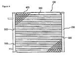
- the condenser 100 includes, as shown in FIG. 4 , a pair of header tanks 200, each of which has a passage through which a heat exchanging medium is passed therein, a plurality of tubes 300 through each of which the heat exchanging medium flows, and a plurality of corrugated fins 400 placed between the tubes 300.
- each of the plurality of tubes 300 are connected to the header tanks 200, and each of the header tanks 200 includes at least one or more baffles 500 therein such that it forms a plurality of passages by the plurality of tubes 300.
- the present invention is directed to the plurality of tubes 300, each of which includes a generally flat body 350, as shown in FIG. 5 , that has predetermined values in length (an axis X), height (an axis Y) and width (an axis Z) directions thereof.
- the body 350 is provided with a plurality of refrigerant passages 340, each of which is passed through the interior thereof in the length direction thereof (along the axis X).
- Each of the refrigerant passages 340 includes a plurality of inside passages 320 and a pair of outside passages 330 provided on the outermost both ends of the body 350.
- each of the inside passages 320 has a first curved portion 321 that is made by changing a predetermined curve 321a over at least a time or more to form a curve changing point protruding in the width direction of the body 350, thereby forming a turbulence activating part 321b thereon, and a second curved portion 322 that is formed opposite to the first curved portion 321 in the width direction thereof and is connected slowly to the first curved portion 321 to thereby form a curve closed face.
- the second curved portion 322 is made by changing a predetermined curve 322a over at least a time or more to form a curve changing point protruding in the width direction of the body 350, thereby forming a turbulence activating part 322b thereon.
- each of the curves 321a and 322a constituting the first and second curved portions 321 and 322 is formed in the same curvature as a circle.
- each of the curves 321a and 322a constituting the first and second curved portions 321 and 322 is formed in the same curvature as an oval, as shown in FIGS. 8 and 9 .
- the curves 321a and 322a constituting the first and second curved portions 321 and 322 are connected in such a fashion that the curve having the curvature of the circle and the curve having the curvature of the oval are arranged in an arbitrary order, as shown in FIGS. 10 and 11 .
- the inside passages 320 are formed in the height direction (along the axis y) of the body 350, on condition that the ratio of the width W1 to the height H1 is less than 1 (that is, W1/H1 ⁇ 1).
- the wall thickness can be maintained at a predetermined value even when a hydraulic diameter is set small so as to increase the heat transfer area for improving the performance of the heat exchanger.
- the problem as arisen conventionally that the wall thickness increases as the hydraulic diameter is set small which causes the weight of the heat exchanger tubes 11 to undesirably increase and causes the consumption of the material to be made, thereby rendering the production cost become high, can be fundamentally eliminated.
- the pair of outside passages 330 are disposed on the outermost both ends of the inside passages 320, each of which includes a third curved portion 331 that is formed in such a manner that a part of the curve close to the outermost end of the body 350 has a roughly same shape as the section of the both ends of the body 350, and a fourth curved portion 332 that is formed by connecting the both end points of the third curved portion 331 to thereby form a closed curved face.
- the fourth curved portion 332 is formed in the same shape as any of the first and second curved portions 321 and 322 of each of the inside passages 320, as shown in FIGS. 6 and 7 .
- the third curved portion 331 and the fourth curved portion 332 are disposed in symmetrical relation with each other and the fourth curved portion 332 is of a desirable circular arc shape.
- the fourth curved portion 332 is of a generally straight line shape, as shown in FIG. 13 .
- the turbulence activating parts 321b and 322b are formed in such a manner that a plurality of imaginary lines I2 connecting the turbulence activating parts 321b and 322b of the plurality of inside passages 320 correspond to an imaginary line I1 dividing said body 350 into two equal parts in the height direction of the body 350.
- the turbulence activating parts 321b and 322b are formed in such a manner that a plurality of imaginary lines I3 connecting the turbulence activating parts 321b and 322b of the plurality of inside passages 320 are alternated at a predetermined angle with the imaginary line I1 dividing said body 350 into two equal parts in the height direction of the body 350.
- the turbulence activating parts 321b and 322b are formed in such a manner that a plurality of imaginary lines I2 connecting the turbulence activating parts 321b and 322b of the plurality of inside passages 320 are disposed upwardly and downwardly around the imaginary line I1 dividing said body 350 into two equal parts in the height direction of the body 350.
- the refrigerant that is passed through the inside passages 320 are activated to be turbulent, thereby improving heat transfer performance.
- the hydraulic diameter Dh of each of the inside and outside passages 320 and 330 is equal to or larger than 0.55 mm, and smaller than or equal to 1.55 mm, which is set to satisfy the condition that 0.55 mm ⁇ Dh ⁇ 1.55 mm.
- the shortest thickness t1 in the height direction of the body 350 of the thickness from the inner surface of each of the inside passages 320 to the outer surface of the body 350 can be maintained constantly without any increment.
- a value that is obtained by dividing the length L1 of the definite straight line, which connects the center points of the two curves adjacent among the curves 321a constituting the first curved portion 321, into a length L2 of the longest distance between the two curves is equal to or larger than 0.3, and smaller than or equal to 0.8, which is set to satisfy the condition that 0.3 ⁇ L1/L2 ⁇ 0.8.
- the angle ⁇ that comes into contact with the curve at the apex of each of the turbulence activating parts 321b and 322b is larger than 80 ° and smaller than 160 °, which is set to satisfy the condition that 80 ° ⁇ ⁇ ⁇ 160 °.
- the shortest thickness t in the width direction of the body 350 among the thickness from the inner surface of each of the outside passages 330 to the outer surface of the body 350 should be set larger by 1.25 times than the shortest thickness t1 in the height direction of the body 350 among the thickness from the inner surface of each of the inside passages 320 to the outer surface of the body 350, which is set to satisfy the condition that t ⁇ 1.25 t1.
- the plurality of imaginary lines I2 connecting the turbulence activating parts 321b and 322b of each of the inside passages 320 are placed perpendicularly to an imaginary line I5 in the height direction of the body 350.
- a shortest thickness t2 in the width direction of the body 350 among the thickness in the width direction between the inside passages 320 should be equal to or larger than 0.15min and equal to or smaller than 0.35mm, which is set to satisfy the condition that 0.15 mm ⁇ t2 ⁇ 0.35 mm.
- the shortest thickness t2 in the width direction of the body 350 of the thickness in the width direction between the inside passages 320 should be equal to or smaller than the shortest thickness t in the width direction of the body 350 of the thickness from the inner surface of each of the outside passages 330 to the outer surface of the body 350, which is set to satisfy the condition that t2 ⁇ t.
- the shortest thickness t2 in the width direction of the body 350 of the thickness in the width direction between the inside passages 320 should be equal to or smaller than the shortest thickness t1 in the height direction of the body 350 of the thickness from the inner surface of each of the inside passages 320 to the outer surface of the body 350, which is set to satisfy the condition that t2 ⁇ t1.
- a Freon refrigerant has been mainly used as a heat exchanging medium that flows within the above-mentioned heat exchanger tube 300.
- the Freon refrigerant is treated as one of causes that make the earth warm, so that the control for use of it becomes gradually strengthened.
- many studies for replacing the Freon refrigerant with a carbon dioxide refrigerant as most worth noticing at next generation have been made all over the world.
- the carbon dioxide has some advantages that the operating compression ratio is low such that the volume efficiency is excellent and the heat transfer characteristic is extremely excellent such that the difference between the temperature on the inlet to which air as a secondary fluid flows and the temperature on the outlet from which refrigerant flows is relatively small when compared with the existing refrigerant. This exhibits many advantages as the refrigerant as well as exhibits a high degree of applicability to a heat pump.
- the carbon dioxide flowing through an inlet 610 is moved to an internal passage 631 of a second header tank 630 from an internal passage 621 of a first header tank 620 and from a first tube 632 that is inserted into the slots (now shown) on the header tanks in such a manner as to be connected to the internal passage 631 of the second header tank 630.
- the carbon dioxide refrigerant flowing into internal passage 631 of the second header tank 630 is returned to an internal passage 631a of the second header tank 630 adjacent thereto through a return hole (which is omitted in the drawing).
- the carbon dioxide refrigerant is returned again to an internal passage 621a of the first header tank 620 from the internal passage 631a of the second header tank 630 and from a second tube 633 that is inserted into the slots (not shown) on the header tanks in such a manner as to be connected to the internal passage 621a of the first header tank 620.
- the temperature on the outlet of the carbon dioxide refrigerant is substantially close to the temperature on the inlet of the external air.
- the carbon dioxide refrigerant flowing into the internal passage 621 of the first header tank 632 is ejected to the outside through an outlet hole 610a.
- Each of the first and second tubes 632 and 633 as the components of the heat exchanger using the carbon dioxide refrigerant 600 is, as shown in FIGS. 4 to 7 and FIGS. 16 and 17 , comprised of the generally flat body 350 that has predetermined values in length (an axis X), height (an axis Y) and width (an axis Z) directions.
- the refrigerant passage 340 is formed passed through the interior of the flat body 350 in the length (the axis X) direction thereof.
- the refrigerant passage 340 is provided with the plurality of inside passages 320, each of which has the first curved portion 321 that is made by changing the predetermined curve 321a over at least a time or more to form the curve changing point protruding in the width direction of the body 350, by which the turbulence activating part 321b is formed, and the second curved portion 322 that is formed opposite to the first curved portion 321 in the width direction thereof and is connected slowly to the first curved portion 321 to thereby form the curve closed face.
- the second curved portion 322 is made by changing the predetermined curve 322a over at least a time or more to form the curve changing point protruding in the width direction of the body 350, by which the turbulence activating part 322b is formed.
- FIGS. 7 to 14 can be of course applied to the tube embodied in the heat exchanger using the carbon dioxide as the heat exchanging medium.
- a stress caused by the pressure of the carbon dioxide refrigerant more specifically, a stensile stress can be prevented from focusing on a certain part of the refrigerant passage 340.
- the resistant pressure strength is enough such that the carbon dioxide refrigerant can be substantially used as the heat exchanging medium.
- the shortest thickness t2 in the width direction of the body 350 of the thickness in the width direction between the inside passages 320 should be equal to or larger than the shortest thickness t1 in the height direction of the body 350 of the thickness from the inner surface of each of the inside passages 320 to the outer surface of the body 350, which is set to satisfy the condition that t2 ⁇ t1.
- the shortest thickness t2 part in the width direction of the body 350 of the thickness in the width direction between the inside passages 320 is first broken off such that the inside passages 320 respectively function as a single passage. That is to say, the tube is deformed to a substantially cylindrical shape and after that, the shortest thickness t1 part in the height direction of the body 350 of the thickness from the inner surface of each of the inside passages 320 to the outer surface of the body 350 is broken off.
- the tube that satisfies the above condition t2 ⁇ t1 is manufactured, it can be applied to the heat exchanger using the carbon oxide as replaceable refrigerant.
- the heat exchanger tube with a plurality of tumbling toy-shaped passages has the following advantages.
- the stress caused by the operating pressure of a heat exchanging medium can be evenly distributed onto the whole refrigerant passages, not gathered partially on the refrigerant passages, such that a resistant pressure strength is enough, thereby allowing the heat exchanging medium to be substantially replaced with carbon dioxide.
- the tube thickness can be maintained at a predetermined value, even when a hydraulic diameter is set low such that a heat transfer area is increased so as to improve the performance of a heat exchanger, thereby allowing the weight thereof and production cost to be reduced.
- the flux of the refrigerant can be increased by means of turbulence activating parts that face with each other in each of the refrigerant passages such that the thickness of the condensed liquid film can be substantially thin according to the acceleration of the turbulence of the refrigerant, thereby allowing a heat transfer efficiency to be enhanced.
- the refrigerant passing through the refrigerant passages is allowed activated to form the turbulence thereof since the turbulence activating parts face with each other in the width direction thereof, thereby allowing the heat transfer performance thereof to be improved.
Landscapes
- Engineering & Computer Science (AREA)
- Physics & Mathematics (AREA)
- Thermal Sciences (AREA)
- Mechanical Engineering (AREA)
- General Engineering & Computer Science (AREA)
- Geometry (AREA)
- Heat-Exchange Devices With Radiators And Conduit Assemblies (AREA)
Description
- The present invention relates to a heat exchanger tube with a plurality of tumbling toy-shaped passages
US-B1-6 192 978 discloses such a heat exchanger tube and a heat exchanger using the heat exchanger tube as defined in the preamble of claim 1. - Generally, an air conditioning device for a vehicle includes a heat exchanger that is provided with a condenser exchanging refrigerant being at high temperature and pressure delivered from a compressor with an external air to thereby make the heat-exchanged refrigerant liquefied, and with an evaporator that enables the liquefied refrigerant to be varied into air being at a low temperature such that the air around the low temperature air becomes cool.
- Each of the condenser and evaporator includes a plurality of tubes, each of which has a plurality of refrigerant passages through which the refrigerant is passed, a plurality of corrugated fins placed between the tubes in a form of wave, a pair of header tanks that connect the both ends of each of the tubes in such a manner as to communicate with the tubes, and inlet and outlet pipes disposed in each of the header tanks, to and from which the refrigerant flows.
- At that time, the condenser of the heat exchanger as mentioned above is provided with the plurality of flat-shaped tubes, each of which has a multipassage formed therein. This is disclosed in Japanese Patent Publication No.
11-159985 - As shown in
FIGS. 1 and 2 , the above-mentioned conventional heat exchanger is provided with a plurality ofheat exchanger tubes 11, each of which forms a plurality ofrefrigerant passages refrigerant passages - The above-discussed conventional heat exchanger has had the following problems.
- So as to improve the performance of the heat exchanger, typically, it is important to increase a heat transfer area where the refrigerant is heat-exchanged. To do this, there has been provided a method in which a hydraulic diameter is reduced.
- Referring to the above-mentioned conventional heat exchanger as shown in
FIGS. 1 and 2 , the plurality ofrefrigerant passages heat exchanger tube 11, and if the ratio of the width w of each of therefrigerant passages heat exchanger tube 11 having the same size. - As the wall thickness t increases, however, the weight of the
heat exchanger tube 11 increases as well as the production cost is raised due to the unnecessary consumption of the material. - On the other hand,
FIG. 3 shows another conventional heat exchanger, which is disclosed in Japanese Patent Publication No.2000-111290 - As shown in
FIG. 3 , the above-mentioned conventional heat exchanger is provided with a multipassage type offlat tube 5 in which a plurality of generallyoval refrigerant passages 2a that are spaced apart equally, inclined by a predetermined angle α against the direction of an axis y. - Document
US-B 6,289,981 , similarly to documentEP-A 0 881 448 , relates to a multi-bored flat tube has two outermost unit passages located at both ends of the tube and has several intermediate unit passages between the two outermost unit passages. The outermost unit passages may have an inner surface having a cross-section based on a circle, such as a circumferentially smoothly curved shaped cross-section, of which a perfect circular shape or elliptical shape are shown (see, for example,Figures 10A and 10B ), or may have an inner surface having a cross-section based on a circle and having a plurality of inner fins extending in a longitudinal direction of the tube. On the other hand, the intermediate unit passages may have a non-circular based cross-sectional shape, such as rectangular, triangular, trapezoidal shape, or may have a circular based shape, said shapes all including a plurality of inner fins. The major advantage resulting from such a structure is that the tube has a considerable strength against being hit by a stone and has a high heat exchanging performance. - Document
US-B 6,192,978 relates to a process for making micro-multiport tubing for use in automobile air conditioner heat exchangers which tubing is a flat body with a row of side-by-side passageways, which are separated by upright webs. Ports are formed in the tubing during extrusion. These ports are separated by webs, and the webs are extruded so that they have a reduced thickness at their centers ("hour glass shape"; seeFigures 2 and 2 of said document). In response to successive cold working of the body, the webs are changed in shape to a more uniform thickness state (seeFigure 4 of said document). Hence, before cold working, the strain is concentrated at the center of the web. With fifteen percent cold work or more, the amount of grain growth is controlled and the improvement in the metallurgical strength is achieved. - The conventional heat exchangers as mentioned above has failed to improve the heat transfer efficiency thereof.
- If an extruding speed increases by a predetermined value more than during the extruding process of the tube manufacturing, in addition, the above-mentioned conventional type of the heat exchangers undesirably form a pin hole on the external side of each of the tubes such that the pin hole is not filled even in the brazing process thereof, which results in the increment of the generation of the defective heat exchanger. To produce a good quality of heat exchanger, therefore, the tube should be manufactured only at the predetermined extruding speed, which of course will cause the productivity thereof to be undesirably low.
- The present invention is directed to a heat exchanger tube with a plurality of tumbling toy-shaped passages that has a generally flat body having predetermined values in length, height and width directions, said plurality of refrigerant passages formed passed through the interior of said flat body in the length direction thereof, said heat exchanger tube comprising: said refrigerant passages provided with a plurality of inside passages, each of which has a first curved portion that is made by connecting a plurality of parts of a circle or of an oval to make a slope of tangent in the connection portion thereof change abruptly to form a curve changing point protruding in the direction of said refrigerant passage which is the width direction of said body, by which turbulence activating part are formed, and has a second curved portion that is formed opposite to said first curved portion and is connected slowly to said first curved portion to thereby form single circular or oval convex surfaces, respectively, on the upper and lower sides thereof in the direction of said tube; and a pair of outside passages disposed on the outermost both ends of said plurality of inside passages.
- The invention is also directed to a heat exchanger comprising: a plurality of tubes as described above, said plurality of tubes being spaced apart equally through which a heat exchanging medium flows; a plurality of corrugated fins disposed between said tubes; and a pair of header tanks spaced apart equally in parallel relation with each other such that the both ends of each of said tubes communicate with each other, through which said heat exchanging medium flows. ]
- Accordingly, the present invention is directed to a heat exchanger tube with a tumbling toy-shaped passage and a heat exchanger using the heat exchanger tube that substantially obviates one or more problems due to limitations and disadvantages of the related art.
- An object of the present invention is to provide a heat exchanger tube with a tumbling toy-shaped passage and a heat exchanger using the heat exchanger tube that can maintain a tube thickness at a predetermined value, even when a hydraulic diameter is set low such that a heat transfer area increases so as to improve the performance of a heat exchanger, thereby allowing the weight of the tube and the production cost thereof to be reduced, that can evenly distribute the stress caused by the operating pressure of a heat exchanging medium onto a plurality of refrigerant passages, not gathered partially on the refrigerant passages, such that a resistant pressure strength is substantially enough, thereby allowing the heat exchanging medium to be substantially replaced with carbon dioxide, that can make, in case where the tube is applied in a condenser, the film of a condensed liquid substantially thin in thickness by means of turbulence activating parts that face with each other in each of the refrigerant passages, thereby allowing a heat transfer efficiency to be enhanced, and that can make the refrigerant passing through the refrigerant passages activated to form the turbulence thereof since the turbulence activating parts face with each other in the width direction thereof, thereby allowing the heat transfer performance thereof to be improved.
- Additional advantages, objects, and features of the invention will be set forth in part in the description which follows and in part will become apparent to those having ordinary skill in the art upon examination of the following or may be learned from practice of the invention. The objectives and other advantages of the invention may be realized and attained by the structure particularly pointed out in the written description and claims hereof as well as the appended drawings.
- According to an aspect of the present invention, there is provided a heat exchanger tube with a plurality of tumbling toy-shaped passages that has a generally flat body having predetermined values in length, height and width directions, the plurality of refrigerant passages formed passed through the interior of the flat body in the length direction thereof, the heat exchanger tube including: each of the plurality of refrigerant passages is provided with a plurality of inside passages, each of which has a first curved portion that is made by changing a predetermined curve over at least a time or more to form a curve changing point protruding in the width direction of the body by which turbulence activating parts are formed, and has a second curved portion that is formed opposite to the first curved portion and is connected slowly to the first curved portion to thereby form a curve closed face, and with a pair of outside passages disposed on the outermost both ends of the plurality of inside passages.
- According to another aspect of the present invention, there is provided a heat exchanger including: a plurality of tubes, each of which is comprised of a plurality of inside passages, each of which has a first curved portion that is made by changing a predetermined curve over at least a time or more to form a curve changing point protruding in the width direction of a body, by which turbulence activating parts are formed, and has a second curved portion that is formed opposite to the first curved portion and is connected slowly to the first curved portion to thereby form a curve closed face, and a pair of outside passages disposed on the outermost both ends of the plurality of inside passages, the plurality of tubes spaced apart equally through each of which a heat exchanging medium flows; and a pair of header tanks that are spaced apart equally in parallel relation with each other such that the both ends of each of the tubes communicate with each other, through which the heat exchanging medium flows.
- In the drawings;
-
FIG.1 is a sectional view of the prior art heat exchanger tube; -
FIG.2 is a sectional view of another type of the prior art heat exchanger tube; -
FIG.3 is a sectional view of still another type of the prior art heat exchanger tube; -
FIG. 4 is a top view of the condenser of a heat exchanger to which a heat exchanger tube according to one embodiment of the present invention is applied; -
FIG. 5 is a perspective view of the external appearance of the heat exchanger tube according to the one embodiment of the present invention; -
FIG. 6 is a sectional view taken along the line "A-A" inFIG. 4 ; -
FIG. 7 is a sectional view of a heat exchanger tube according to another embodiment of the present invention wherein two turbulence activating parts are provided each curved portion; -
FIGS. 8 to 14 are partly sectional views of the heat exchanger tube according to another embodiment of the present invention; -
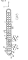
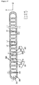
FIG. 15 is a perspective view of the external appearance of the heat exchanger to which the heat exchanger tube according to the present invention is applied, wherein a heat exchanging medium is used with carbon dioxide; and -
FIGS. 16 and17 are sectional views of the embodiments of the heat exchanger tube inFIG. 15 . - Reference will now be made in detail to the preferred embodiments of the present invention, examples of which are illustrated in the accompanying drawings.
- First, an explanation of the condenser of a heat exchanger to which the principles of the present invention are applied will be given before the configuration of a heat exchanger tube according to the present invention is discussed.
- The
condenser 100 includes, as shown inFIG. 4 , a pair ofheader tanks 200, each of which has a passage through which a heat exchanging medium is passed therein, a plurality oftubes 300 through each of which the heat exchanging medium flows, and a plurality ofcorrugated fins 400 placed between thetubes 300. - The both ends of each of the plurality of
tubes 300 are connected to theheader tanks 200, and each of theheader tanks 200 includes at least one ormore baffles 500 therein such that it forms a plurality of passages by the plurality oftubes 300. - The present invention is directed to the plurality of
tubes 300, each of which includes a generallyflat body 350, as shown inFIG. 5 , that has predetermined values in length (an axis X), height (an axis Y) and width (an axis Z) directions thereof. - The
body 350 is provided with a plurality ofrefrigerant passages 340, each of which is passed through the interior thereof in the length direction thereof (along the axis X). - Each of the
refrigerant passages 340 includes a plurality ofinside passages 320 and a pair ofoutside passages 330 provided on the outermost both ends of thebody 350. - As shown in
FIGS. 6 and7 , each of theinside passages 320 has a firstcurved portion 321 that is made by changing apredetermined curve 321a over at least a time or more to form a curve changing point protruding in the width direction of thebody 350, thereby forming aturbulence activating part 321b thereon, and a secondcurved portion 322 that is formed opposite to the firstcurved portion 321 in the width direction thereof and is connected slowly to the firstcurved portion 321 to thereby form a curve closed face. - In the same manner as the first
curved portion 321, the secondcurved portion 322 is made by changing apredetermined curve 322a over at least a time or more to form a curve changing point protruding in the width direction of thebody 350, thereby forming aturbulence activating part 322b thereon. - As shown in
FIG. 12 , each of thecurves curved portions - In another preferred embodiment of the present invention, each of the
curves curved portions FIGS. 8 and 9 . - In still another preferred embodiment of the present invention, the
curves curved portions FIGS. 10 and11 . - The
inside passages 320 are formed in the height direction (along the axis y) of thebody 350, on condition that the ratio of the width W1 to the height H1 is less than 1 (that is, W1/H1<1). - Under the above-mentioned condition, the wall thickness can be maintained at a predetermined value even when a hydraulic diameter is set small so as to increase the heat transfer area for improving the performance of the heat exchanger.
- That is to say, the problem as arisen conventionally that the wall thickness increases as the hydraulic diameter is set small which causes the weight of the
heat exchanger tubes 11 to undesirably increase and causes the consumption of the material to be made, thereby rendering the production cost become high, can be fundamentally eliminated. - On the other hand, the pair of
outside passages 330 are disposed on the outermost both ends of theinside passages 320, each of which includes a thirdcurved portion 331 that is formed in such a manner that a part of the curve close to the outermost end of thebody 350 has a roughly same shape as the section of the both ends of thebody 350, and a fourthcurved portion 332 that is formed by connecting the both end points of the thirdcurved portion 331 to thereby form a closed curved face. - In this case, the fourth
curved portion 332 is formed in the same shape as any of the first and secondcurved portions inside passages 320, as shown inFIGS. 6 and7 . - And, as shown in
Fig.12 , the thirdcurved portion 331 and the fourthcurved portion 332 are disposed in symmetrical relation with each other and the fourthcurved portion 332 is of a desirable circular arc shape. - The fourth
curved portion 332 is of a generally straight line shape, as shown inFIG. 13 . - On the other hand, as shown in
FIGS. 8 and12 , theturbulence activating parts turbulence activating parts inside passages 320 correspond to an imaginary line I1 dividing saidbody 350 into two equal parts in the height direction of thebody 350. - And, as shown in
FIG. 14 , theturbulence activating parts turbulence activating parts inside passages 320 are alternated at a predetermined angle with the imaginary line I1 dividing saidbody 350 into two equal parts in the height direction of thebody 350. - And, as shown in
FIG. 10 , theturbulence activating parts turbulence activating parts inside passages 320 are disposed upwardly and downwardly around the imaginary line I1 dividing saidbody 350 into two equal parts in the height direction of thebody 350. - Since the
turbulence activating parts inside passages 320 are activated to be turbulent, thereby improving heat transfer performance. - On the other hand, the hydraulic diameter Dh of each of the inside and
outside passages - Even when the above-mentioned hydraulic diameter is set, the shortest thickness t1 in the height direction of the
body 350 of the thickness from the inner surface of each of theinside passages 320 to the outer surface of thebody 350 can be maintained constantly without any increment. - As shown in
FIGS. 6 and7 , a value that is obtained by dividing the length L1 of the definite straight line, which connects the center points of the two curves adjacent among thecurves 321a constituting the firstcurved portion 321, into a length L2 of the longest distance between the two curves is equal to or larger than 0.3, and smaller than or equal to 0.8, which is set to satisfy the condition that 0.3 ≤ L1/L2 ≤ 0.8. - The reason why the above condition is satisfied is that if the longest distance value L2 is over a predetermined value, the protruding height of each of the
turbulence activating parts - To the contrary, if the longest distance value L2 is under the predetermined value, the protruding height of each of the
turbulence activating parts - As shown in
Fig. 6 , the angle α that comes into contact with the curve at the apex of each of theturbulence activating parts - In the above embodiment of the present invention, the shortest thickness t in the width direction of the
body 350 among the thickness from the inner surface of each of theoutside passages 330 to the outer surface of thebody 350 should be set larger by 1.25 times than the shortest thickness t1 in the height direction of thebody 350 among the thickness from the inner surface of each of theinside passages 320 to the outer surface of thebody 350, which is set to satisfy the condition that t ≥ 1.25 t1. - As shown in
FIG. 8 , on the other hand, the plurality of imaginary lines I2 connecting theturbulence activating parts inside passages 320 are placed perpendicularly to an imaginary line I5 in the height direction of thebody 350. - In the above embodiment of the present invention, a shortest thickness t2 in the width direction of the
body 350 among the thickness in the width direction between theinside passages 320 should be equal to or larger than 0.15min and equal to or smaller than 0.35mm, which is set to satisfy the condition that 0.15 mm ≤ t2 ≤ 0.35 mm. - On the other hand, the shortest thickness t2 in the width direction of the
body 350 of the thickness in the width direction between theinside passages 320 should be equal to or smaller than the shortest thickness t in the width direction of thebody 350 of the thickness from the inner surface of each of theoutside passages 330 to the outer surface of thebody 350, which is set to satisfy the condition that t2 ≤ t. - And, the shortest thickness t2 in the width direction of the
body 350 of the thickness in the width direction between theinside passages 320 should be equal to or smaller than the shortest thickness t1 in the height direction of thebody 350 of the thickness from the inner surface of each of theinside passages 320 to the outer surface of thebody 350, which is set to satisfy the condition that t2 ≤ t1. - If the above-mentioned conditions are satisfied, even when the extruding speed increases during the extruding process of the tube manufacturing work there is no the pin hole on the outer side of each of the tubes.
- Since no pin hole is formed, therefore, the extruding speed can increase to thereby improve the productivity thereof.
- The preferred embodiments of the heat exchanger tube and the heat exchanger using the heat exchanger tube have been described until now.
- On the other hand, a Freon refrigerant has been mainly used as a heat exchanging medium that flows within the above-mentioned
heat exchanger tube 300. However, the Freon refrigerant is treated as one of causes that make the earth warm, so that the control for use of it becomes gradually strengthened. Under the above situation, many studies for replacing the Freon refrigerant with a carbon dioxide refrigerant as most worth noticing at next generation have been made all over the world. - The carbon dioxide has some advantages that the operating compression ratio is low such that the volume efficiency is excellent and the heat transfer characteristic is extremely excellent such that the difference between the temperature on the inlet to which air as a secondary fluid flows and the temperature on the outlet from which refrigerant flows is relatively small when compared with the existing refrigerant. This exhibits many advantages as the refrigerant as well as exhibits a high degree of applicability to a heat pump.
- As described above, an explanation of the heat exchanger using the
carbon dioxide 600 as a heat exchanging medium will be discussed on the basis of the flowing process of the refrigerant with reference toFIG. 16 . - As shown in
FIG. 16 , first, the carbon dioxide flowing through aninlet 610 is moved to aninternal passage 631 of asecond header tank 630 from aninternal passage 621 of afirst header tank 620 and from afirst tube 632 that is inserted into the slots (now shown) on the header tanks in such a manner as to be connected to theinternal passage 631 of thesecond header tank 630. - In the process where the carbon dioxide refrigerant flows to the
internal passage 631 of thesecond header tank 630, it is thermally exchanged with the external air through thefirst tube 632 andcorrugated fins 634. On the other hand, the carbon dioxide refrigerant flowing intointernal passage 631 of thesecond header tank 630 is returned to aninternal passage 631a of thesecond header tank 630 adjacent thereto through a return hole (which is omitted in the drawing). Next, the carbon dioxide refrigerant is returned again to aninternal passage 621a of thefirst header tank 620 from theinternal passage 631a of thesecond header tank 630 and from asecond tube 633 that is inserted into the slots (not shown) on the header tanks in such a manner as to be connected to theinternal passage 621a of thefirst header tank 620. - In the process where the carbon dioxide refrigerant flows to the
internal passage 621a of thefirst header tank 620, it is thermally exchanged again with the external air through thesecond tube 633 and thecorrugated fins 634. - Through the above-mentioned process, the temperature on the outlet of the carbon dioxide refrigerant is substantially close to the temperature on the inlet of the external air.
- On the other hand, the carbon dioxide refrigerant flowing into the
internal passage 621 of thefirst header tank 632 is ejected to the outside through anoutlet hole 610a. - Each of the first and
second tubes carbon dioxide refrigerant 600 is, as shown inFIGS. 4 to 7 andFIGS. 16 and17 , comprised of the generallyflat body 350 that has predetermined values in length (an axis X), height (an axis Y) and width (an axis Z) directions. Therefrigerant passage 340 is formed passed through the interior of theflat body 350 in the length (the axis X) direction thereof. - The
refrigerant passage 340 is provided with the plurality ofinside passages 320, each of which has the firstcurved portion 321 that is made by changing thepredetermined curve 321a over at least a time or more to form the curve changing point protruding in the width direction of thebody 350, by which theturbulence activating part 321b is formed, and the secondcurved portion 322 that is formed opposite to the firstcurved portion 321 in the width direction thereof and is connected slowly to the firstcurved portion 321 to thereby form the curve closed face. - In the same manner as the first
curved portion 321, the secondcurved portion 322 is made by changing thepredetermined curve 322a over at least a time or more to form the curve changing point protruding in the width direction of thebody 350, by which theturbulence activating part 322b is formed. - The preferred embodiments of the present invention as illustrated in
FIGS. 7 to 14 can be of course applied to the tube embodied in the heat exchanger using the carbon dioxide as the heat exchanging medium. - By adopting the heat exchanger tube according to the present invention, a stress caused by the pressure of the carbon dioxide refrigerant, more specifically, a stensile stress can be prevented from focusing on a certain part of the
refrigerant passage 340. - In addition, the resistant pressure strength is enough such that the carbon dioxide refrigerant can be substantially used as the heat exchanging medium.
- Moreover, as shown in
FIGS. 16 and17 , the shortest thickness t2 in the width direction of thebody 350 of the thickness in the width direction between theinside passages 320 should be equal to or larger than the shortest thickness t1 in the height direction of thebody 350 of the thickness from the inner surface of each of theinside passages 320 to the outer surface of thebody 350, which is set to satisfy the condition that t2 ≥ t1. - High pressure and durability tests are carried out for the tube manufactured under the above condition, and as a result, the shortest thickness t2 part in the width direction of the
body 350 of the thickness in the width direction between theinside passages 320 is first broken off such that theinside passages 320 respectively function as a single passage. That is to say, the tube is deformed to a substantially cylindrical shape and after that, the shortest thickness t1 part in the height direction of thebody 350 of the thickness from the inner surface of each of theinside passages 320 to the outer surface of thebody 350 is broken off. - If the tube that satisfies the above condition t2 ≥ t1 is manufactured, it can be applied to the heat exchanger using the carbon oxide as replaceable refrigerant.
- As clearly understood from the foregoing, the heat exchanger tube with a plurality of tumbling toy-shaped passages according to the present invention has the following advantages.
- First, the stress caused by the operating pressure of a heat exchanging medium can be evenly distributed onto the whole refrigerant passages, not gathered partially on the refrigerant passages, such that a resistant pressure strength is enough, thereby allowing the heat exchanging medium to be substantially replaced with carbon dioxide.
- Second, the tube thickness can be maintained at a predetermined value, even when a hydraulic diameter is set low such that a heat transfer area is increased so as to improve the performance of a heat exchanger, thereby allowing the weight thereof and production cost to be reduced.
- Third, in case where the tube is applied in a condenser, the flux of the refrigerant can be increased by means of turbulence activating parts that face with each other in each of the refrigerant passages such that the thickness of the condensed liquid film can be substantially thin according to the acceleration of the turbulence of the refrigerant, thereby allowing a heat transfer efficiency to be enhanced.
- Finally, the refrigerant passing through the refrigerant passages is allowed activated to form the turbulence thereof since the turbulence activating parts face with each other in the width direction thereof, thereby allowing the heat transfer performance thereof to be improved.
- The forgoing embodiments are merely exemplary and are not to be construed as limiting the present invention. The present teachings can be readily applied to other types of apparatuses. The description of the present invention is intended to be illustrative, and not to limit the scope of the claims. Many alternatives, modifications, and variations will be apparent to those skilled in the art.
Claims (37)
- A heat exchanger tube (300) with a plurality of tumbling toy-shaped passages that has a generally flat body (350) having predetermined values in length, height and width directions, said plurality of refrigerant passages (340) formed passed through the interior of said flat body (350) in the length direction thereof, said heat exchanger tube comprising:said refrigerant passages (340) provided with a plurality of inside passages (320) and a pair of outside passages (330) disposed on the outermost both ends of said plurality of inside passages (320), characterised in that each of the inside passasges (320) has a first curved portion (321) that is made by connecting a plurality of parts (321 a) of a circle or of an oval to make a slope of tangent in the connection portion thereof change abruptly to form a curve changing point protruding in the direction of said refrigerant passage (340) which is the width direction of said body (350), by which turbulence activating parts (321b) are formed, and has a second curved portion (322) that is formed opposite to said first curved portion (321) and is connected slowly to said first curved portion (321) to thereby form single circular or oval convex surfaces, respectively, on the upper and lower sides thereof in the direction of said tube.
- The heat exchanger tube according to claim 1, wherein each of said outside passages (330) comprises a third curved portion (331) formed in such a manner that a part of the curve close to the outermost end of said body (350) has a roughly same shape as the section of the both ends of said body, and a fourth curved portion (332) formed by connecting the both end points of said third curved portion (331) to thereby form a closed curved face.
- The heat exchanger tube according to claim 2, wherein said fourth curved portion (332) is formed in the same shape as any of said first and second curved portions (321 and 322) of each of said inside passages (320).
- The heat exchanger tube according to claim 2, wherein said third curved portion (331) and said fourth curved portion (332) are disposed in symmetrical relation with each other.
- The heat exchanger tube according to claim 2, wherein said fourth curved portion (332) is of a generally circular arc shape.
- The heat exchanger tube according to claim 2, wherein said fourth curved portion (332) is of a generally straight-line shape.
- The heat exchanger tube according to claim 1, wherein said curves (321a and 322a) constituting said first and second curved portions (321 and 322) are connected in such a fashion that said curve having the curvature of a circle and said curve having the curvature of an oval are arranged in an arbitrary order.
- The heat exchanger tube according to claim 1, wherein said turbulence activating parts (321b and 322b) are formed in such a manner that a plurality of second imaginary lines (I2) connecting said turbulence activating parts (321b and 322b) of said plurality of inside passages (320) correspond to a first imaginary line (I1) dividing said body 350 into two equal parts in the height direction of the body 350.
- The heat exchanger tube according to claim 1, wherein said turbulence activating parts (321b and 322b) are formed in such a manner that a plurality of third imaginary lines (I3) connecting said turbulence activating parts (321b and 322b) of said plurality of inside passages (320) are alternated at a predetermined angle with said first imaginary line (I1) dividing said body 350 into two equal parts in the height direction of the body 350.
- The heat exchanger tube according to claim 1, wherein said turbul-ence activating parts (321b and 322b) are formed in such a manner that a plurality of third imaginary lines (I3) connecting said turbulence activating parts (321b and 322b) of said plurality of inside passages (320) are disposed upwardly and downwardly around said first imaginary line (I1) dividing said body 350 into two equal parts in the height direction of the body 350.
- The heat exchanger tube according to claim 5, wherein a value that is obtained by dividing a length (L1) of the definite straight line, which connects the center points of the two curves adjacent among said curves constituting said first curved portion (321), into a length (L2) of the longest distance between the two curves is equal to or larger than 0.3, and smaller than or equal to 0.8, which is set to satisfy the condition 0.3 ≤ L1/L2 ≤ 0.8.
- The heat exchanger tube according to claim 1, wherein said inside and outside passages (320 and 330) have hydraulic diameters (Dh) those are equal to or larger than 0.55 mm, and smaller than or equal to 1.55 mm, which is set to satisfy the condition that 0.55 mm ≤ Dh ≤ 1.55 mm.
- The heat exchanger tube according to claim 1, wherein an angle α that comes into contact with the curve at the apex of each of said turbulence activating parts (321b and 322b) is larger than 80 ° and smaller than 160 °, which is set to satisfy the condition that 80 ° < α < 160 °.
- The heat exchanger tube according to claim 13, wherein a shortest thickness (t) in the width direction of said body of the thickness from the inner surface of each of said outside passages (330) to the outer surface of said body (350) is set larger by 1.25 times than the shortest thickness (t1) in the height direction of said body of the thickness from the inner surface of each of said inside passages (320) to the outer surface of said body (350), which is set to satisfy the condition that t ≥ 1.25 t1.
- The heat exchanger tube according to claim 1, wherein said plurality of second imaginary lines (I2) connecting said turbulence activating parts (321 b and 322b) of each of said inside passages (320) are placed perpendicularly to said fifth imaginary line (I5) in the height direction of said body (350).
- The heat exchanger tube according to claim 15, wherein a shortest thickness (t2) in the width direction of said body of the thickness in the width direction between said inside passages (320) is equal to or larger than 0. 15 mm, and equal to or smaller than 0.35 mm, which is represented by the following inequality: 0.15 mm ≤ t2 ≤ 0.35 mm.
- The heat exchanger tube according to claim 1, wherein said shortest thickness (t2) in the width direction of said body of the thickness in the width direction between said inside passages (320) is equal to or smaller than said shortest thickness (t) in the width direction of said body of the thickness from the inner surface of each of said outside passages (330) to the outer surface of said body (350), which is set to satisfy the condition that t2 ≤ t.
- The heat exchanger tube according to claim 1, wherein said shortest thickness (t2) in the width direction of said body of the thickness in the width direction between said inside passages (320) is equal to or smaller than said shortest thickness (t1) in the height direction of said body of the thickness from the inner surface of each of said inside passages (320) to the outer surface of said body (350), which is set to satisfy the condition that t2 ≤ t1.
- A heat exchanger comprising:a plurality of tubes (300) as claimed in claim 1, said plurality of tubes (300) being spaced apart equally through which a heat exchanging medium flows;a plurality of corrugated fins (400 and 634) disposed between said tubes (300); anda pair of header tanks (200) spaced apart equally in parallel relation with each other such that the both ends of each of said tubes (300) communicate with each other, through which said heat exchanging medium flows.
- The heat exchanger according to claim 19, wherein said heat exchanging medium is carbon dioxide.
- The heat exchanger according to claim 19 or claim 20, wherein each of said outside passages (330) comprises a third curved portion (331) formed in such a manner that a part of the curve close to the outermost end of said body (350) has a roughly same shape as the section of the both ends of said body, and a fourth curved portion (332) formed by connecting the both end points of said third curved portion (331) to thereby form a closed curved face.
- The heat exchanger according to claim 21, wherein said fourth curved portion (332) is formed in the same shape as any of said first and second curved portions (321 and 322) of each of said inside passages (320).
- The heat exchanger according to claim 21, wherein said third curved portion (331) and said fourth curved portion (332) are disposed in symmetrical relation with each other.
- The heat exchanger according to claim 21, wherein said fourth curved portion (332) is of a generally circular arc shape.
- The heat exchanger according to claim 21, wherein said fourth curved portion (332) is of a generally straight-line shape.
- The heat exchanger according to claim 19 or claim 20, wherein said curves. (321 a and 322a) constituting said first and second curved portions (321 and 322) are connected in such a fashion that said curves having the curvature of a circle and said curves having the curvature of an oval are arranged in an arbitrary order.
- The heat exchanger according to claim 19 or claim 20, wherein said turbulence activating parts (321b and 322b) are formed in such a manner that a plurality of second imaginary lines (I2) connecting said turbulence activating parts of said plurality of inside passages (320) correspond to the first imaginary line (I1) dividing said body 350 into two equal parts in the height direction of the body 350.
- The heat exchanger according to claim 19 or claim 20, wherein said turbulence activating parts (321b and 322b) are formed in such a manner that a plurality of third imaginary lines (I3) connecting said turbulence activating parts (321 and 322) of said plurality of inside passages (320) are alternated at a predetermined angle with said first imaginary line (I1) dividing said body 350 into two equal parts in the height direction of the body 350.
- The heat exchanger according to claim 19 or claim 20, wherein said turbulence activating parts (321b and 322b) are formed in such a manner that a plurality of fourth imaginary lines (I2) connecting said turbulence activating parts (321b and 322b) of said plurality of inside passages (320) are disposed upwardly and downwardly around said first imaginary line (I1) dividing said body 350 into two equal parts in the height direction of the body 350.
- The heat exchanger according to claim 24, wherein a value that is obtained by dividing a length (L1) of the definite straight line, which connects the center points of the two curves adjacent among said curves constituting said first curved portion (321), into a length (L2) of the longest distance between the two curves is equal to or larger than 0.3, and smaller than or equal to 0.8, which is set to satisfy the condition that 0.3 ≤ L1/L2 ≤ 0.8.
- The heat exchanger according to claim 19 or claim 20, wherein said inside and outside passages (320 and 330) have hydraulic diameters (Dh) those are equal to or larger than 0.55 mm, and smaller than or equal to 1.55 mm, which is set to satisfy the condition that 0.55 mm ≤ Dh ≤ 1.55 mm.
- The heat exchanger according to claim 19 or claim 20, wherein an angle α that comes into contact with the curve at the apex of each of said turbulence activating parts (321b and 322b) is larger than 80 ° and smaller than 160°, which is set to satisfy the condition that 80 ° < α < 160 °.
- The heat exchanger according to claim 32, wherein a shortest thickness (t) in the width direction of said body of the thickness from the inner surface of each of said outside passages (330) to the outer surface of said body (350) is set larger by 1.25 times than the shortest thickness (t1) in the height direction of said body of the thickness from the inner surface of each of said inside passages (320) to the outer surface of said body (350), which is set to satisfy the condition that t ≥ 1.25 t1.
- The heat exchanger according to claim 19 or claim 20, wherein said plurality of second imaginary lines (I2) connecting said turbulence activating parts (321b and 322b) of each of said inside passages (320) are placed perpendicularly to said fifth imaginary line (I5) in the height direction of said body (350).
- The heat exchanger according to claim 34, wherein a shortest thickness (t2) in the width direction of said body among the thickness in the width direction between said inside passages (320) is equal to or larger than 0.15mm and equal to or smaller than 0.35 mm, which is set to satisfy the condition that 0.15 mm ≤ t2 ≤ 0.35 mm.
- The heat exchanger according to claim 19 or claim 20, wherein said shortest thickness (t2) in the width direction of said body of the thickness in the width direction between said inside passages (320) is equal to or smaller than said shortest thickness (t) in the width direction of said body (350) of the thickness from the inner surface of each of said outside passages (330) to the outer surface of said body, which is set to satisfy the condition that t2 ≤ t.
- The heat exchanger according to claim 20, wherein said shortest thickness (t2) in the width direction of said body of the thickness in the width direction between said inside passages (320) is equal to or larger than said shortest thickness (t1) in the height direction of said body of the thickness from the inner surface of each of said inside passages (320) to the outer surface of said body (350), which is set to satisfy the condition that t2 ≥ t1.
Applications Claiming Priority (3)
| Application Number | Priority Date | Filing Date | Title |
|---|---|---|---|
| KR20020005595 | 2002-01-31 | ||
| KR2002005595 | 2002-01-31 | ||
| PCT/KR2002/001217 WO2003064952A1 (en) | 2002-01-31 | 2002-06-26 | Heat exchanger tube with tumbling toy-shaped passages and heat exchanger using the same |
Publications (3)
| Publication Number | Publication Date |
|---|---|
| EP1476709A1 EP1476709A1 (en) | 2004-11-17 |
| EP1476709A4 EP1476709A4 (en) | 2006-04-19 |
| EP1476709B1 true EP1476709B1 (en) | 2010-06-23 |
Family
ID=27607055
Family Applications (1)
| Application Number | Title | Priority Date | Filing Date |
|---|---|---|---|
| EP02741495A Expired - Lifetime EP1476709B1 (en) | 2002-01-31 | 2002-06-26 | Heat exchanger tube with tumbling toy-shaped passages and heat exchanger using the same |
Country Status (7)
| Country | Link |
|---|---|
| US (1) | US6854512B2 (en) |
| EP (1) | EP1476709B1 (en) |
| JP (1) | JP3962798B2 (en) |
| KR (1) | KR100906769B1 (en) |
| CN (1) | CN100338425C (en) |
| DE (1) | DE60236816D1 (en) |
| WO (1) | WO2003064952A1 (en) |
Families Citing this family (38)
| Publication number | Priority date | Publication date | Assignee | Title |
|---|---|---|---|---|
| AU2003272090B2 (en) * | 2002-10-02 | 2008-08-07 | Showa Denko K.K. | Heat exchanging tube and heat exchanger |
| JP4213496B2 (en) * | 2003-03-26 | 2009-01-21 | カルソニックカンセイ株式会社 | Heat exchanger |
| US7559355B2 (en) * | 2003-06-20 | 2009-07-14 | Halla Climate Control Corporation | Tube for heat exchanger |
| US7080683B2 (en) * | 2004-06-14 | 2006-07-25 | Delphi Technologies, Inc. | Flat tube evaporator with enhanced refrigerant flow passages |
| BRPI0519937A2 (en) * | 2005-02-02 | 2009-09-08 | Carrier Corp | heat exchanger and refrigerant vapor compression system |
| DE102005016540A1 (en) * | 2005-04-08 | 2006-10-12 | Behr Gmbh & Co. Kg | Multichannel flat tube |
| DE102005048227A1 (en) * | 2005-10-07 | 2007-04-12 | Behr Gmbh & Co. Kg | Radiator, cooling circuit, air conditioner for a motor vehicle air conditioning system and air conditioning for a motor vehicle |
| JP4898300B2 (en) * | 2006-05-30 | 2012-03-14 | 昭和電工株式会社 | Evaporator |
| CN101454559B (en) * | 2006-06-01 | 2012-07-18 | 贝洱两合公司 | Heat exchanger |
| WO2008131732A1 (en) * | 2007-04-25 | 2008-11-06 | Wolfgang Feldmann | Heat transfer unit for heating systems and surfaces and railway point heater |
| WO2008141626A1 (en) * | 2007-05-22 | 2008-11-27 | Institut Für Luft- Und Kältetechnik Gemeinnützige Gmbh | Rear wall condenser for domestic refrigerators and freezers |
| JP2009063228A (en) * | 2007-09-06 | 2009-03-26 | Showa Denko Kk | Flat heat transfer tube |
| US20090159253A1 (en) * | 2007-12-21 | 2009-06-25 | Zaiqian Hu | Heat exchanger tubes and combo-coolers including the same |
| US8776874B2 (en) * | 2007-12-30 | 2014-07-15 | Valeo, Inc. | Heat exchanger tubes and methods for enhancing thermal performance and reducing flow passage plugging |
| WO2009086894A1 (en) * | 2008-01-10 | 2009-07-16 | Behr Gmbh & Co. Kg | Extruded tube for a heat exchanger |
| CN101776357B (en) * | 2009-01-09 | 2011-12-28 | 三花丹佛斯(杭州)微通道换热器有限公司 | Heat exchanger |
| JP2011153814A (en) * | 2009-09-30 | 2011-08-11 | Daikin Industries Ltd | Heat exchanging flat tube |
| JP5562769B2 (en) * | 2010-09-01 | 2014-07-30 | 三菱重工業株式会社 | Heat exchanger and vehicle air conditioner equipped with the same |
| CN102269536A (en) * | 2011-08-17 | 2011-12-07 | 三花丹佛斯(杭州)微通道换热器有限公司 | Flat tube used for heat exchanger and heat exchanger with same |
| US9500413B1 (en) | 2012-06-14 | 2016-11-22 | Google Inc. | Thermosiphon systems with nested tubes |
| US9869519B2 (en) * | 2012-07-12 | 2018-01-16 | Google Inc. | Thermosiphon systems for electronic devices |
| US20150101361A1 (en) * | 2013-10-10 | 2015-04-16 | General Electric Company | Sealed system for an appliance |
| JP6262770B2 (en) | 2013-12-21 | 2018-01-17 | 京セラ株式会社 | Heat exchange member and heat exchanger |
| DE102014206612A1 (en) * | 2014-04-04 | 2015-10-29 | Mahle International Gmbh | heat exchangers |
| FR3020670B1 (en) * | 2014-05-05 | 2019-03-22 | Valeo Systemes Thermiques | FLAT TUBE FOR HEAT EXCHANGER |
| CN103968700B (en) * | 2014-05-26 | 2016-08-24 | 赵耀华 | A kind of high efficient heat exchanging water pipe and heat pipe radiant heating/refrigeration system |
| JP6395863B2 (en) * | 2015-01-09 | 2018-09-26 | 三菱電機株式会社 | Heat exchanger and refrigeration cycle apparatus having the heat exchanger |
| US10527362B2 (en) * | 2015-09-21 | 2020-01-07 | Lockheed Martin Corporation | Integrated multi-chamber heat exchanger |
| US10371462B2 (en) | 2015-09-21 | 2019-08-06 | Lockheed Martin Corporation | Integrated multi-chamber heat exchanger |
| KR102634151B1 (en) * | 2015-10-29 | 2024-02-06 | 가부시키가이샤 유에이씨제이 | Aluminum extruded flat perforated tube and heat exchanger |
| DE102017201081A1 (en) * | 2016-01-25 | 2017-07-27 | Hanon Systems | Pipe for a heat exchanger |
| US10451360B2 (en) * | 2016-10-24 | 2019-10-22 | Hamilton Sundstrand Corporation | Heat exchanger with integral anti-icing |
| CN106767013A (en) * | 2016-12-29 | 2017-05-31 | 上海德朗汽车零部件制造有限公司 | A kind of peanut tubular type automobile radiators |
| JP6704361B2 (en) * | 2017-01-13 | 2020-06-03 | 日立ジョンソンコントロールズ空調株式会社 | Air conditioner |
| CN109990507B (en) * | 2018-01-02 | 2024-09-24 | 佛山市顺德区美的饮水机制造有限公司 | Heat exchange device and water dispenser having the same |
| FR3101139B1 (en) * | 2019-09-24 | 2022-03-18 | Safran | HEAT EXCHANGER FOR TURBOMACHINE, TURBOMACHINE AND METHOD FOR MANUFACTURING THE EXCHANGER |
| JP7496832B2 (en) * | 2019-10-10 | 2024-06-07 | 三菱電機株式会社 | HEAT EXCHANGER, HEAT EXCHANGER UNIT, REFRIGERATION CYCLE DEVICE, AND METHOD FOR MANUFACTURING HEAT EXCHANGE MEMBER |
| US20250052503A1 (en) * | 2023-08-08 | 2025-02-13 | Bradley John Klein | Microchannel heat exchanger |
Family Cites Families (19)
| Publication number | Priority date | Publication date | Assignee | Title |
|---|---|---|---|---|
| US4512069A (en) * | 1983-02-04 | 1985-04-23 | Motoren-Und Turbinen-Union Munchen Gmbh | Method of manufacturing hollow flow profiles |
| JPS60196181U (en) * | 1984-05-30 | 1985-12-27 | 三菱マテリアル株式会社 | heat exchanger tube |
| JPS6233288A (en) * | 1985-08-02 | 1987-02-13 | Showa Alum Corp | Heat exchanger in automobile cooling and heating unit |
| JPH02230091A (en) * | 1989-03-01 | 1990-09-12 | Hitachi Ltd | Serpentine heat exchanger |
| JP2935071B2 (en) * | 1991-01-23 | 1999-08-16 | 昭和アルミニウム株式会社 | Flat tubes for heat exchangers |
| JPH06300473A (en) * | 1993-04-19 | 1994-10-28 | Sanden Corp | Flat refrigerant pipe |
| JPH0875384A (en) * | 1994-07-01 | 1996-03-19 | Hitachi Ltd | Heat transfer tube for non-azeotropic mixed refrigerant, heat exchanger using the heat transfer tube, assembling method, and refrigeration / air conditioner using the heat exchanger |
| DE19719263C2 (en) * | 1997-05-07 | 2002-04-25 | Valeo Klimatech Gmbh & Co Kg | Flat tube evaporator with vertical longitudinal direction of the flat tubes in motor vehicles |
| JPH1144498A (en) * | 1997-05-30 | 1999-02-16 | Showa Alum Corp | Flat perforated tube for heat exchanger and heat exchanger using the tube |
| JPH11159985A (en) * | 1997-11-28 | 1999-06-15 | Mitsubishi Heavy Ind Ltd | Heat exchanger |
| US6216776B1 (en) * | 1998-02-16 | 2001-04-17 | Denso Corporation | Heat exchanger |
| US5904206A (en) * | 1998-02-25 | 1999-05-18 | General Motors Corporation | Heat exchanger flow tube with improved header to tube end stress resistance |
| JP2000018867A (en) * | 1998-06-23 | 2000-01-18 | Mitsubishi Heavy Ind Ltd | Tube material for heat exchanger and heat exchanger |
| DE19845336A1 (en) | 1998-10-01 | 2000-04-06 | Behr Gmbh & Co | Multi-channel flat tube |
| KR100522668B1 (en) * | 1998-11-14 | 2005-12-30 | 한라공조주식회사 | Heat exchanger tube |
| JP4018279B2 (en) * | 1999-01-19 | 2007-12-05 | カルソニックカンセイ株式会社 | Flat tube for heat exchanger |
| JP4026277B2 (en) * | 1999-05-25 | 2007-12-26 | 株式会社デンソー | Heat exchanger |
| JP3313086B2 (en) | 1999-06-11 | 2002-08-12 | 昭和電工株式会社 | Tube for heat exchanger |
| US6192978B1 (en) * | 1999-10-27 | 2001-02-27 | Brazeway, Inc. | Micro-multiport (MMP) tubing with improved metallurgical strength and method for making said tubing |
-
2002
- 2002-06-25 KR KR1020020035530A patent/KR100906769B1/en not_active Expired - Fee Related
- 2002-06-26 EP EP02741495A patent/EP1476709B1/en not_active Expired - Lifetime
- 2002-06-26 JP JP2003564505A patent/JP3962798B2/en not_active Expired - Fee Related
- 2002-06-26 WO PCT/KR2002/001217 patent/WO2003064952A1/en not_active Ceased
- 2002-06-26 DE DE60236816T patent/DE60236816D1/en not_active Expired - Lifetime
- 2002-06-26 CN CNB02827721XA patent/CN100338425C/en not_active Expired - Fee Related
- 2002-08-13 US US10/217,902 patent/US6854512B2/en not_active Expired - Lifetime
Also Published As
| Publication number | Publication date |
|---|---|
| KR20030065269A (en) | 2003-08-06 |
| WO2003064952A1 (en) | 2003-08-07 |
| CN100338425C (en) | 2007-09-19 |
| KR100906769B1 (en) | 2009-07-10 |
| CN1618003A (en) | 2005-05-18 |
| JP2005516176A (en) | 2005-06-02 |
| DE60236816D1 (en) | 2010-08-05 |
| JP3962798B2 (en) | 2007-08-22 |
| US20030141048A1 (en) | 2003-07-31 |
| US6854512B2 (en) | 2005-02-15 |
| EP1476709A1 (en) | 2004-11-17 |
| EP1476709A4 (en) | 2006-04-19 |
Similar Documents
| Publication | Publication Date | Title |
|---|---|---|
| US6854512B2 (en) | Heat exchanger tube and heat exchanger using the same | |
| US6289981B1 (en) | Multi-bored flat tube for use in a heat exchanger and heat exchanger including said tubes | |
| US6523603B2 (en) | Double heat exchanger with condenser and radiator | |
| US6125922A (en) | Refrigerant condenser | |
| JP4347961B2 (en) | Multiway flat tube | |
| US6209202B1 (en) | Folded tube for a heat exchanger and method of making same | |
| US7219716B2 (en) | Heat exchanger | |
| EP2175223A1 (en) | Refrigerant evaporator | |
| WO2004099695A1 (en) | Heat exchanger | |
| JPH0587752B2 (en) | ||
| US10267573B2 (en) | Polyhedral array heat transfer tube | |
| US20020011332A1 (en) | Refrigerant tube for heat exchangers | |
| US7174953B2 (en) | Stacking-type, multi-flow, heat exchanger | |
| US5934365A (en) | Heat exchanger | |
| EP1703245B1 (en) | Heat exchanger | |
| AU1373000A (en) | Regulating device for a coolant circuit of an air conditioning system | |
| US6612367B2 (en) | Heat exchanger and method of making same | |
| US20070144719A1 (en) | Heat exchanger | |
| WO2001061263A1 (en) | Heat exchanger | |
| KR101062652B1 (en) | Tube for heat exchanger | |
| KR100998955B1 (en) | Tube for heat exchanger | |
| JP2001263976A (en) | Heat exchanger | |
| KR100509638B1 (en) | tube element for laminated type heat exchanger | |
| JP2002062062A (en) | Heat exchanger | |
| WO2025201489A1 (en) | Fin, and heat exchanger and heat exchange system having same |
Legal Events
| Date | Code | Title | Description |
|---|---|---|---|
| PUAI | Public reference made under article 153(3) epc to a published international application that has entered the european phase |
Free format text: ORIGINAL CODE: 0009012 |
|
| 17P | Request for examination filed |
Effective date: 20040823 |
|
| AK | Designated contracting states |
Kind code of ref document: A1 Designated state(s): AT BE CH CY DE DK ES FI FR GB GR IE IT LI LU MC NL PT SE TR |
|
| AX | Request for extension of the european patent |
Extension state: AL LT LV MK RO SI |
|
| A4 | Supplementary search report drawn up and despatched |
Effective date: 20060302 |
|
| 17Q | First examination report despatched |
Effective date: 20090205 |
|
| GRAP | Despatch of communication of intention to grant a patent |
Free format text: ORIGINAL CODE: EPIDOSNIGR1 |
|
| GRAS | Grant fee paid |
Free format text: ORIGINAL CODE: EPIDOSNIGR3 |
|
| GRAA | (expected) grant |
Free format text: ORIGINAL CODE: 0009210 |
|
| AK | Designated contracting states |
Kind code of ref document: B1 Designated state(s): DE FR GB IT PT SE |
|
| REF | Corresponds to: |
Ref document number: 60236816 Country of ref document: DE Date of ref document: 20100805 Kind code of ref document: P |
|
| PG25 | Lapsed in a contracting state [announced via postgrant information from national office to epo] |
Ref country code: SE Free format text: LAPSE BECAUSE OF FAILURE TO SUBMIT A TRANSLATION OF THE DESCRIPTION OR TO PAY THE FEE WITHIN THE PRESCRIBED TIME-LIMIT Effective date: 20100623 |
|
| PG25 | Lapsed in a contracting state [announced via postgrant information from national office to epo] |
Ref country code: PT Free format text: LAPSE BECAUSE OF FAILURE TO SUBMIT A TRANSLATION OF THE DESCRIPTION OR TO PAY THE FEE WITHIN THE PRESCRIBED TIME-LIMIT Effective date: 20101025 |
|
| PG25 | Lapsed in a contracting state [announced via postgrant information from national office to epo] |
Ref country code: IT Free format text: LAPSE BECAUSE OF FAILURE TO SUBMIT A TRANSLATION OF THE DESCRIPTION OR TO PAY THE FEE WITHIN THE PRESCRIBED TIME-LIMIT Effective date: 20100623 |
|
| PLBE | No opposition filed within time limit |
Free format text: ORIGINAL CODE: 0009261 |
|
| STAA | Information on the status of an ep patent application or granted ep patent |
Free format text: STATUS: NO OPPOSITION FILED WITHIN TIME LIMIT |
|
| GBPC | Gb: european patent ceased through non-payment of renewal fee |
Effective date: 20100923 |
|
| 26N | No opposition filed |
Effective date: 20110324 |
|
| REG | Reference to a national code |
Ref country code: DE Ref legal event code: R097 Ref document number: 60236816 Country of ref document: DE Effective date: 20110323 |
|
| PG25 | Lapsed in a contracting state [announced via postgrant information from national office to epo] |
Ref country code: GB Free format text: LAPSE BECAUSE OF NON-PAYMENT OF DUE FEES Effective date: 20100923 |
|
| REG | Reference to a national code |
Ref country code: DE Ref legal event code: R082 Ref document number: 60236816 Country of ref document: DE Representative=s name: KOEPE & PARTNER PATENTANWAELTE, DE |
|
| REG | Reference to a national code |
Ref country code: FR Ref legal event code: CD Owner name: HALLA VISTEON CLIMATE CONTROL CORPORATION Effective date: 20130827 |
|
| REG | Reference to a national code |
Ref country code: DE Ref legal event code: R082 Ref document number: 60236816 Country of ref document: DE Representative=s name: SCHWABE SANDMAIR MARX PATENTANWAELTE RECHTSANW, DE Effective date: 20130910 Ref country code: DE Ref legal event code: R081 Ref document number: 60236816 Country of ref document: DE Owner name: HANON SYSTEMS, KR Free format text: FORMER OWNER: HALLA CLIMATE CONTROL CORP., DAEJEON, KR Effective date: 20130910 Ref country code: DE Ref legal event code: R082 Ref document number: 60236816 Country of ref document: DE Representative=s name: KOEPE & PARTNER PATENTANWAELTE, DE Effective date: 20130910 Ref country code: DE Ref legal event code: R081 Ref document number: 60236816 Country of ref document: DE Owner name: HALLA VISTEON CLIMATE CONTROL CORP., KR Free format text: FORMER OWNER: HALLA CLIMATE CONTROL CORP., DAEJEON, KR Effective date: 20130910 |
|
| REG | Reference to a national code |
Ref country code: FR Ref legal event code: PLFP Year of fee payment: 15 |
|
| REG | Reference to a national code |
Ref country code: DE Ref legal event code: R082 Ref document number: 60236816 Country of ref document: DE Representative=s name: SSM SANDMAIR PATENTANWAELTE RECHTSANWALT PARTN, DE Ref country code: DE Ref legal event code: R082 Ref document number: 60236816 Country of ref document: DE Representative=s name: SCHWABE SANDMAIR MARX PATENTANWAELTE RECHTSANW, DE |
|
| REG | Reference to a national code |
Ref country code: DE Ref legal event code: R082 Ref document number: 60236816 Country of ref document: DE Representative=s name: SSM SANDMAIR PATENTANWAELTE RECHTSANWALT PARTN, DE Ref country code: DE Ref legal event code: R082 Ref document number: 60236816 Country of ref document: DE Representative=s name: SCHWABE SANDMAIR MARX PATENTANWAELTE RECHTSANW, DE Ref country code: DE Ref legal event code: R081 Ref document number: 60236816 Country of ref document: DE Owner name: HANON SYSTEMS, KR Free format text: FORMER OWNER: HALLA VISTEON CLIMATE CONTROL CORP., DAEJEON, KR |
|
| REG | Reference to a national code |
Ref country code: FR Ref legal event code: CD Owner name: HANON SYSTEMS Effective date: 20161212 |
|
| REG | Reference to a national code |
Ref country code: FR Ref legal event code: PLFP Year of fee payment: 16 |
|
| REG | Reference to a national code |
Ref country code: FR Ref legal event code: PLFP Year of fee payment: 17 |
|
| PGFP | Annual fee paid to national office [announced via postgrant information from national office to epo] |
Ref country code: DE Payment date: 20190612 Year of fee payment: 18 |
|
| PGFP | Annual fee paid to national office [announced via postgrant information from national office to epo] |
Ref country code: FR Payment date: 20200512 Year of fee payment: 19 |
|
| REG | Reference to a national code |
Ref country code: DE Ref legal event code: R119 Ref document number: 60236816 Country of ref document: DE |
|
| PG25 | Lapsed in a contracting state [announced via postgrant information from national office to epo] |
Ref country code: DE Free format text: LAPSE BECAUSE OF NON-PAYMENT OF DUE FEES Effective date: 20210101 |
|
| PG25 | Lapsed in a contracting state [announced via postgrant information from national office to epo] |
Ref country code: FR Free format text: LAPSE BECAUSE OF NON-PAYMENT OF DUE FEES Effective date: 20210630 |