EP1475855A1 - Secondary battery-use pole plate material - Google Patents
Secondary battery-use pole plate material Download PDFInfo
- Publication number
- EP1475855A1 EP1475855A1 EP03705150A EP03705150A EP1475855A1 EP 1475855 A1 EP1475855 A1 EP 1475855A1 EP 03705150 A EP03705150 A EP 03705150A EP 03705150 A EP03705150 A EP 03705150A EP 1475855 A1 EP1475855 A1 EP 1475855A1
- Authority
- EP
- European Patent Office
- Prior art keywords
- electrode
- sheet
- punched
- embossing
- projections
- Prior art date
- Legal status (The legal status is an assumption and is not a legal conclusion. Google has not performed a legal analysis and makes no representation as to the accuracy of the status listed.)
- Withdrawn
Links
Images

Classifications
-
- H—ELECTRICITY
- H01—ELECTRIC ELEMENTS
- H01M—PROCESSES OR MEANS, e.g. BATTERIES, FOR THE DIRECT CONVERSION OF CHEMICAL ENERGY INTO ELECTRICAL ENERGY
- H01M4/00—Electrodes
- H01M4/02—Electrodes composed of, or comprising, active material
- H01M4/64—Carriers or collectors
- H01M4/70—Carriers or collectors characterised by shape or form
- H01M4/72—Grids
- H01M4/74—Meshes or woven material; Expanded metal
- H01M4/742—Meshes or woven material; Expanded metal perforated material
-
- H—ELECTRICITY
- H01—ELECTRIC ELEMENTS
- H01M—PROCESSES OR MEANS, e.g. BATTERIES, FOR THE DIRECT CONVERSION OF CHEMICAL ENERGY INTO ELECTRICAL ENERGY
- H01M4/00—Electrodes
- H01M4/02—Electrodes composed of, or comprising, active material
- H01M4/36—Selection of substances as active materials, active masses, active liquids
- H01M4/58—Selection of substances as active materials, active masses, active liquids of inorganic compounds other than oxides or hydroxides, e.g. sulfides, selenides, tellurides, halogenides or LiCoFy; of polyanionic structures, e.g. phosphates, silicates or borates
-
- H—ELECTRICITY
- H01—ELECTRIC ELEMENTS
- H01M—PROCESSES OR MEANS, e.g. BATTERIES, FOR THE DIRECT CONVERSION OF CHEMICAL ENERGY INTO ELECTRICAL ENERGY
- H01M4/00—Electrodes
- H01M4/02—Electrodes composed of, or comprising, active material
- H01M4/64—Carriers or collectors
-
- H—ELECTRICITY
- H01—ELECTRIC ELEMENTS
- H01M—PROCESSES OR MEANS, e.g. BATTERIES, FOR THE DIRECT CONVERSION OF CHEMICAL ENERGY INTO ELECTRICAL ENERGY
- H01M4/00—Electrodes
- H01M4/02—Electrodes composed of, or comprising, active material
- H01M4/64—Carriers or collectors
- H01M4/66—Selection of materials
- H01M4/661—Metal or alloys, e.g. alloy coatings
-
- H—ELECTRICITY
- H01—ELECTRIC ELEMENTS
- H01M—PROCESSES OR MEANS, e.g. BATTERIES, FOR THE DIRECT CONVERSION OF CHEMICAL ENERGY INTO ELECTRICAL ENERGY
- H01M4/00—Electrodes
- H01M4/02—Electrodes composed of, or comprising, active material
- H01M4/64—Carriers or collectors
- H01M4/70—Carriers or collectors characterised by shape or form
- H01M4/72—Grids
- H01M4/74—Meshes or woven material; Expanded metal
-
- Y—GENERAL TAGGING OF NEW TECHNOLOGICAL DEVELOPMENTS; GENERAL TAGGING OF CROSS-SECTIONAL TECHNOLOGIES SPANNING OVER SEVERAL SECTIONS OF THE IPC; TECHNICAL SUBJECTS COVERED BY FORMER USPC CROSS-REFERENCE ART COLLECTIONS [XRACs] AND DIGESTS
- Y02—TECHNOLOGIES OR APPLICATIONS FOR MITIGATION OR ADAPTATION AGAINST CLIMATE CHANGE
- Y02E—REDUCTION OF GREENHOUSE GAS [GHG] EMISSIONS, RELATED TO ENERGY GENERATION, TRANSMISSION OR DISTRIBUTION
- Y02E60/00—Enabling technologies; Technologies with a potential or indirect contribution to GHG emissions mitigation
- Y02E60/10—Energy storage using batteries
Definitions
- the present invention relates to an electrode sheet material for use in secondary batteries. More specifically, the present invention relates to a sheet material for secondary battery electrodes having a three-dimensional structure with an increased surface area.
- Some examples of electrode components of a secondary battery include negative or positive electrodes of Ni-molecular hydrogen batteries and substrate plates of Ni-Cd batteries.
- Such an electrode of a secondary battery can be explained as follows by taking as an example a positive electrode of Ni-molecular hydrogen battery.
- Sintered electrodes are electrodes comprising a punched metal plate with a sintered layer of a nickel powder. An active material predominantly comprised of nickel hydroxide is coated onto the sintered layer.
- a sintered electrode is prepared by mixing nickel powder with water, applying the resulting slurry onto both surfaces of a punched metal plate, and performing sintering at 1000° C.
- the resulting electrode having a sintered layer is immersed in an aqueous solution of nickel salt and then in an alkaline aqueous solution to convert the nickel into nickel hydroxide.
- the pore size of the sintered layer is about 10 microns, and the layer has superior ability to collect electric currents. However, since the porosity thereof is as low as about 75%, it is difficult to achieve a high density of active materials in the layer.
- a non-sintered electrode is an electrode in which an active material (nickel hydroxide) is applied to a substrate which is comprised of a sponge-like nickel structure (a foamed nickel body).
- an active material nickel hydroxide
- a substrate which is comprised of a sponge-like nickel structure (a foamed nickel body).
- a non-sintered electrode is manufactured by mixing an active material mainly comprising nickel hydroxide to form a paste, applying the resulting paste to the substrate, drying the paste, and then performing pressing of the substrate to obtain a predetermined size.
- the foamed nickel body is prepared by forming foamed polyurethane into the form of a plate or sheet, immersing the foamed polyurethane plate (sheet) in a carbon powder suspension, and drying the body to deposit on it an electrically conductive carbon on which it is possible to carry out electroplating of the body. After completion of electroplating with nickel, the polyurethane plate (sheet) is burned off, and if necessary, the resulting foamed nickel body is subjected to annealing to prepare a porous nickel substrate. Although the porous nickel substrate has a porosity of as high as 95%, its mechanical properties are degraded due to its high porosity.
- the porous nickel substrate has a porosity of as high as about 95% but its pore diameter is as large as 100 - 500 microns, it is necessary to collect electric currents effectively through an active material.
- non-sintered, i.e., paste-type electrodes are mainly used as high capacity electrodes.
- An object of the present invention is to provide an electrode sheet material for secondary batteries from which a battery having a higher level of output and a higher level of capacity than those prepared from electrode sheet materials of the prior art can be manufactured.
- Another object of the present invention is to provide an electrode sheet material which can be produced easily at a low cost and is superior in mechanical strength to those of the prior art.
- Efficiency means the ratio with respect to a theoretical value of 289 mAh/g which is a value which assumes that electronic reactions have occurred.
- the efficiency is almost 100%, but the efficiency is as low as about 65% in the case of a non-sintered electrode in which only an active material powder is applied to the electrode substrate.
- the inventors manufactured a positive electrode component using a sheet material prepared from a punched plate which has been subjected to pressing, and they found that such a positive electrode could exhibit a great degree of improvement in properties and thereby accomplished the present invention.
- An electrode sheet material of the present invention can be used not only as a positive electrode component but also as a negative electrode component.
- the electrode can be used as a negative electrode of Ni-hydrogen secondary batteries, for example.
- An electrode in the form of a copper foil is preferred as a negative electrode. Namely, a hydrogen-storing alloy powder was mixed with an electrically conductive agent and a binding agent to prepare a paste. The resulting paste was applied to a punched plate, which was then formed by pressing. The thus-prepared negative electrode was used to prepare a battery which was determined to have a capacity of about 300 - 330 mAh/g, which is 80 - 90% of the theoretical value of 372 mAh/g.
- the present inventors achieved the present invention based on the recognition that battery properties are much improved by increasing the surface area of the above-mentioned punched plate.
- the present invention can be summarized as follows:
- Figure 1 is a flow diagram which shows a manufacturing process for an electrode sheet material for use in secondary batteries of the present invention.
- a mother sheet (a SPCC sheet, for example), preferably with a thickness of 0.035 - 0.1mm, is punched with a press.
- a mother sheet a SPCC sheet, for example
- the ratio of the punched area / the area before punching can be in the range of 30 - 50%.
- the thus-prepared punched sheet may be a steel sheet (foil) or a copper sheet (foil), It is also conceivable to use a sheet (foil) of another suitable metal or other material.
- Nickel plating is then applied to the sheet.
- the nickel plating may be carried out by electroplating or spraying, or sputtering, and the like. From the view point of economy, electroplating is preferable.
- a clad material of a steel or copper sheet (or foil) with a nickel foil may be used.
- the formation of a clad embodiment will also be called "plating", Since such nickel plating is already known in the art, a further detailed explanation will be omitted.
- Nickel plating can be carried out before punching. However, from a practical standpoint, it is preferable to carry out nickel plating on a punched sheet.
- the thickness of the plating layer Since the purpose of providing a plating layer is to improve corrosion resistance, electrical conductivity, and uniformity of surface properties, there is no limit on the thickness of the plating layer so long as such a purpose can be achieved. Usually, the thickness may be about 1.5 - 5.0 ⁇ m.
- the resulting punched sheet is transferred to a press- forming step to form projections on either a single side or on both sides.
- the illustrated embodiment shows forming by embossing.
- Such press-forming is carried out as shown in Figure 1 by embossing. Sometimes it is preferable to carry out embossing when an electrode sheet of a high strength is necessary. On the other hand, in order to utilize work-hardening during press-forming, it is desirable in some cases to employ the later-described break-through forming which can achieve a large working ratio.
- Figures 2(a) and 2(b) show sectional views of other types of projections, which can be shaped by press-forming into corrugated sections (Fig.2(a)), convex-concave sections (Fig. 2(b), and the like.
- the sectional shape of the projections can be a corrugated shape or a convex-concave shape, etc., and either one can be selected in view of the properties to be obtained when the electrode sheet is incorporated into a secondary battery.
- press-forming followed by break-through may be carried out.
- This type of forming does not increase the surface area so much as does embossing, but it increases the ability to hold an active material on an electrode.
- Figures 3 (a) and (b) show sectional views of a projection subjected to breaking-through. Comparing Figure 3(a), which shows a mere projection, with Figure 3(b), which shows a projection which has been subjected to breaking-through, a projection which has been broken through has a greater degree of work hardening than a mere projection, providing the punched sheet with a greater degree of stiffness. However, when burrs remain after forming, it is thought be troublesome to treat them at a later stage of manufacturing.
- Such projections may be provided in either one of the surfaces of a punched sheet.
- projections formed by embossing may be provided on both surfaces thereof so that effect of enlarging the surface area can be utilized more efficiently.
- the effectiveness of the projections as a three-dimensional structure is more marked.
- the electrode sheet material of the present invention is employed as electrodes, due to the facts that a punched sheet can be used and projections can be provided on the surface, and the surface area can be increased, especially by means of embossing, the following advantages can be obtained.
- Japanese Patent Application Unexamined Laid-Open Specification Hei 10-106580 discloses an electrode sheet material produced just by embossing. It is stated therein that the ability to hold an active material is poor for punched metals, laths, and metallic screens. It is also stated that since the porosity of punched metals is 50% at most, the ability to hold active material is not enough even if burrs are provided around the punched holes.
- a previously prepared base sheet was subjected to press-forming by punching as shown in the flow diagram of Figure 1.
- Nickel plating was carried out by electrical plating. After plating and annealing, the resulting punched sheet was subjected to press-forming by embossing.
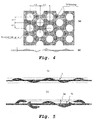
- Figure 4(a) is a plan view of the resulting electrode sheet
- Figure 4(b) is a sectional view thereof. It is noted therefrom that embossing was applied to both surfaces of the sheet, and the punched areas were also subjected to embossing. In the figures, the units of measure are mm.
- the surface area of the electrode sheet was increased by about 12% in comparison with the case in which just punching was performed. Since battery properties such as battery capacity and power density are determined by surface reactions of electrode sheets, an increase in surface area can be expected to result in an increase in capacity and power output. Based on a simple calculation, it is expected that these properties can be increased by about 12%.
- Figure 5 (a) is a sectional view of a punched sheet which was subjected to press-forming by embossing. As shown therein, height h is the embossed depth (mm). As shown in Figure 5(b), when the embossed depth is enlarged beyond a certain depth, i.e., a critical depth (hc), some of the foot portions formed by embossing are locally broken through. The depth of the embossed projections when the foot portion is broken through is the maximum depth (hm).
- an electrode sheet material with an increased surface area i.e., improved battery properties
- a nickel plating material can be employed in place of nickel, the material costs of the electrode of the present invention can be reduced markedly.
- the present invention is particularly advantageous in the industry in view of improvements with respect to battery properties and its economy.
Landscapes
- Chemical & Material Sciences (AREA)
- Chemical Kinetics & Catalysis (AREA)
- Electrochemistry (AREA)
- General Chemical & Material Sciences (AREA)
- Inorganic Chemistry (AREA)
- Engineering & Computer Science (AREA)
- Materials Engineering (AREA)
- Cell Electrode Carriers And Collectors (AREA)
- Secondary Cells (AREA)
- Battery Electrode And Active Subsutance (AREA)
Abstract
An electrode sheet material for use in secondary batteries is provided.
According to the present invention, battery properties can be improved and its
economy is excellent. Punching is carried out on steel or copper sheet (foil), and
after nickel plating, press-forming to form projections on the surface, e.g.,
embossing is carried out so that a three-dimensional structure is prepared.
Optionally, broken-through portions may be provided in the foot portion.
Description
The present invention relates to an electrode sheet material for use in
secondary batteries. More specifically, the present invention relates to a sheet
material for secondary battery electrodes having a three-dimensional structure
with an increased surface area.
In recent years, electrical equipment, and particularly, small-sized
electronic equipment such as mobile phones, have come to be widely used. The
demand for electric power sources therefor has also been increasing, while an
improvement in the performance of secondary batteries is also required.
Intensive research for improved secondary batteries is being carried out. More
recently, a variety of materials for use in a secondary battery with a high level of
output and a high level of capacity are under development.
Some examples of electrode components of a secondary battery include
negative or positive electrodes of Ni-molecular hydrogen batteries and substrate
plates of Ni-Cd batteries. Such an electrode of a secondary battery can be
explained as follows by taking as an example a positive electrode of Ni-molecular
hydrogen battery. There are two types of electrodes; one is a sintered electrode
and the other is non-sintered one, i.e., a paste electrode. There is room for further
research on a positive electrode in order to increase the capacity of a battery
because a positive electrode has a lower filling density of active material but
occupies a larger percent of the volume within a battery than a negative electrode.
Sintered electrodes are electrodes comprising a punched metal plate with a
sintered layer of a nickel powder. An active material predominantly comprised
of nickel hydroxide is coated onto the sintered layer.
In general, a sintered electrode is prepared by mixing nickel powder with
water, applying the resulting slurry onto both surfaces of a punched metal plate,
and performing sintering at 1000° C. The resulting electrode having a sintered
layer is immersed in an aqueous solution of nickel salt and then in an alkaline
aqueous solution to convert the nickel into nickel hydroxide.
The pore size of the sintered layer is about 10 microns, and the layer has
superior ability to collect electric currents. However, since the porosity thereof is
as low as about 75%, it is difficult to achieve a high density of active materials in
the layer.
A non-sintered electrode is an electrode in which an active material (nickel
hydroxide) is applied to a substrate which is comprised of a sponge-like nickel
structure (a foamed nickel body).
A non-sintered electrode is manufactured by mixing an active material
mainly comprising nickel hydroxide to form a paste, applying the resulting paste
to the substrate, drying the paste, and then performing pressing of the substrate to
obtain a predetermined size.
The foamed nickel body is prepared by forming foamed polyurethane into
the form of a plate or sheet, immersing the foamed polyurethane plate (sheet) in a
carbon powder suspension, and drying the body to deposit on it an electrically
conductive carbon on which it is possible to carry out electroplating of the body.
After completion of electroplating with nickel, the polyurethane plate (sheet) is
burned off, and if necessary, the resulting foamed nickel body is subjected to
annealing to prepare a porous nickel substrate. Although the porous nickel
substrate has a porosity of as high as 95%, its mechanical properties are degraded
due to its high porosity.
Thus, since the porous nickel substrate has a porosity of as high as about
95% but its pore diameter is as large as 100 - 500 microns, it is necessary to
collect electric currents effectively through an active material.
Presently, therefore, non-sintered, i.e., paste-type electrodes are mainly
used as high capacity electrodes.
An object of the present invention is to provide an electrode sheet material
for secondary batteries from which a battery having a higher level of output and a
higher level of capacity than those prepared from electrode sheet materials of the
prior art can be manufactured.
Another object of the present invention is to provide an electrode sheet
material which can be produced easily at a low cost and is superior in mechanical
strength to those of the prior art.
In order to achieve such objects of the present invention, the present
inventors have listed the problems in the art as follows.
First, "efficiency" is considered. Efficiency means the ratio with respect to
a theoretical value of 289 mAh/g which is a value which assumes that electronic
reactions have occurred.
In the case of a sintered electrode, the efficiency is almost 100%, but the
efficiency is as low as about 65% in the case of a non-sintered electrode in which
only an active material powder is applied to the electrode substrate.
There are many proposals to improve efficiency, such as applying Co
compounds as an additive to a substrate, or increasing electrical conductivity by
coating nickel hydroxide powder with a Co(OH)2 layer so as to further increase
electrical conductivity of the oxide layer. According to these prior art methods,
an efficiency of 100% or more has been achieved. However, it is highly desired
to further improve efficiency.
Next, it is also a problem whether charging and discharging are carried out
efficiently using an active material held on a substrate of an electrode. It is
supposed that the charging and discharging are influenced by the contact surface
area between an electrical current collector and an active material on the electrical
current collector interface and by the distance between the collector and the
active material. Thus, the following countermeasures are conceivable.
On the basis of the above findings, the inventors manufactured a positive
electrode component using a sheet material prepared from a punched plate which
has been subjected to pressing, and they found that such a positive electrode
could exhibit a great degree of improvement in properties and thereby
accomplished the present invention.
An electrode sheet material of the present invention can be used not only
as a positive electrode component but also as a negative electrode component.
The electrode can be used as a negative electrode of Ni-hydrogen secondary
batteries, for example. An electrode in the form of a copper foil is preferred as a
negative electrode. Namely, a hydrogen-storing alloy powder was mixed with an
electrically conductive agent and a binding agent to prepare a paste. The
resulting paste was applied to a punched plate, which was then formed by
pressing. The thus-prepared negative electrode was used to prepare a battery
which was determined to have a capacity of about 300 - 330 mAh/g, which is 80
- 90% of the theoretical value of 372 mAh/g.
The present inventors achieved the present invention based on the
recognition that battery properties are much improved by increasing the surface
area of the above-mentioned punched plate.
The present invention can be summarized as follows:
Figure 1 is a flow diagram which shows a manufacturing process for an
electrode sheet material for use in secondary batteries of the present invention.
As shown therein, a mother sheet (a SPCC sheet, for example), preferably
with a thickness of 0.035 - 0.1mm, is punched with a press. There are no limits
with respect to the shape, number, and size of the punched portions so long as
they can exhibit properties which are required for an electrode plate. In general,
the ratio of the punched area / the area before punching can be in the range of 30
- 50%.
The thus-prepared punched sheet may be a steel sheet (foil) or a copper
sheet (foil), It is also conceivable to use a sheet (foil) of another suitable metal or
other material.
Nickel plating is then applied to the sheet. The nickel plating may be
carried out by electroplating or spraying, or sputtering, and the like. From the
view point of economy, electroplating is preferable. In another embodiment, a
clad material of a steel or copper sheet (or foil) with a nickel foil may be used. In
this specification, for ease of explanation, the formation of a clad embodiment
will also be called "plating", Since such nickel plating is already known in the
art, a further detailed explanation will be omitted.
Nickel plating can be carried out before punching. However, from a practical
standpoint, it is preferable to carry out nickel plating on a punched sheet.
Since the purpose of providing a plating layer is to improve corrosion
resistance, electrical conductivity, and uniformity of surface properties, there is
no limit on the thickness of the plating layer so long as such a purpose can be
achieved. Usually, the thickness may be about 1.5 - 5.0 µm.
After plating, the resulting punched sheet is transferred to a press- forming
step to form projections on either a single side or on both sides. The illustrated
embodiment shows forming by embossing.
There is no limit on the shape, number, and size of the projections. If
possible, it is desirable to provide such projections in the un-punched areas.
However, if it is necessary to further increase the surface area, in order to make it
easy to design dies therefor, such projections may be provided without restricting
them to punched areas.
Such press-forming is carried out as shown in Figure 1 by embossing.
Sometimes it is preferable to carry out embossing when an electrode sheet of a
high strength is necessary. On the other hand, in order to utilize work-hardening
during press-forming, it is desirable in some cases to employ the later-described
break-through forming which can achieve a large working ratio.
Figures 2(a) and 2(b) show sectional views of other types of projections,
which can be shaped by press-forming into corrugated sections (Fig.2(a)),
convex-concave sections (Fig. 2(b), and the like. Thus, the sectional shape of the
projections can be a corrugated shape or a convex-concave shape, etc., and either
one can be selected in view of the properties to be obtained when the electrode
sheet is incorporated into a secondary battery. In this embodiment, it is possible
to increase the surface area per unit length, but the forming operation is unstable
because it does not involve drawing, which is involved in press-forming by
embossing.
In another embodiment, instead of the embossing shown in Figure 1, press-forming
followed by break-through may be carried out. This type of forming
does not increase the surface area so much as does embossing, but it increases the
ability to hold an active material on an electrode.
Figures 3 (a) and (b) show sectional views of a projection subjected to
breaking-through. Comparing Figure 3(a), which shows a mere projection, with
Figure 3(b), which shows a projection which has been subjected to breaking-through,
a projection which has been broken through has a greater degree of
work hardening than a mere projection, providing the punched sheet with a
greater degree of stiffness. However, when burrs remain after forming, it is
thought be troublesome to treat them at a later stage of manufacturing.
Such projections may be provided in either one of the surfaces of a
punched sheet. In general, projections formed by embossing may be provided on
both surfaces thereof so that effect of enlarging the surface area can be utilized
more efficiently. In addition, when such projections have broken-through
portions, the effectiveness of the projections as a three-dimensional structure is
more marked.
When the electrode sheet material of the present invention is employed as
electrodes, due to the facts that a punched sheet can be used and projections can
be provided on the surface, and the surface area can be increased, especially by
means of embossing, the following advantages can be obtained.
Japanese Patent Application Unexamined Laid-Open Specification Hei 10-106580
discloses an electrode sheet material produced just by embossing. It is
stated therein that the ability to hold an active material is poor for punched
metals, laths, and metallic screens. It is also stated that since the porosity of
punched metals is 50% at most, the ability to hold active material is not enough
even if burrs are provided around the punched holes.
The effectiveness of the present invention will be explained more
specifically in conjunction with working examples thereof.
In this example, as a positive electrode sheet material for a Ni-hydrogen
battery, punched sheets having a three-dimensional structure with the following
characteristics were manufactured.
Characteristics of punched sheets which were subjected to embossing in
this example are as follows:
| 1) Base Sheet | SPCC Sheet |
| 2) Thickness of the Sheet | 0.035 mm |
| 3) Thickness of Ni Plating | 2.5 micrometers |
| 4) Punching Die | 1.0 mm in diameter |
| 5) Embossing Die | 1.0 mm in diameter |
A previously prepared base sheet was subjected to press-forming by
punching as shown in the flow diagram of Figure 1.
Nickel plating was carried out by electrical plating. After plating and
annealing, the resulting punched sheet was subjected to press-forming by
embossing.
Figure 4(a) is a plan view of the resulting electrode sheet, and Figure 4(b)
is a sectional view thereof. It is noted therefrom that embossing was applied to
both surfaces of the sheet, and the punched areas were also subjected to
embossing. In the figures, the units of measure are mm.
In the illustrated example, it was confirmed that the surface area of the
electrode sheet was increased by about 12% in comparison with the case in which
just punching was performed. Since battery properties such as battery capacity
and power density are determined by surface reactions of electrode sheets, an
increase in surface area can be expected to result in an increase in capacity and
power output. Based on a simple calculation, it is expected that these properties
can be increased by about 12%.
By varying the embossing depth in the embossing, the effect of an increase
in surface area was evaluated.
The results are summarized in Table 1. When the embossing depth was
0.52 mm, the resulting projection was not broken through. However, some of the
samples had projections, after embossing, with broken-through portions
appearing on the side walls (also referred to as "foot portions") of the projections.
| Sample No. | Embossing Depth (mm) | Increase in Surface Area (%) |
| 1 | 0.20 | 8.77 |
| 2 | 0.40 | 16.92 |
| 3 | 0.52 | 23.71 |
| (Note): An increase in surface area is based on the increase with respect to a punched sheet before embossing. |
Figure 5 (a) is a sectional view of a punched sheet which was subjected to
press-forming by embossing. As shown therein, height h is the embossed depth
(mm). As shown in Figure 5(b), when the embossed depth is enlarged beyond a
certain depth, i.e., a critical depth (hc), some of the foot portions formed by
embossing are locally broken through. The depth of the embossed projections
when the foot portion is broken through is the maximum depth (hm).
Since such local broken-through portions are formed in the foot portion
during embossing, the height and waviness of the projections are increased and
the shapes thereof become complicated. Thus, the effectiveness as a three-dimensional
structure becomes marked, i.e., the surface area of the thus-formed
punched sheet is markedly increased, and not only the density of an active
material on the surface thereof but also the holding strength can be increased.
Similar operations were repeated on steel foils (cold rolled steel sheet) and
copper foils to prepare electrode sheet materials, although the characteristics were
a little changed. The results are summarized in Tables 2 and 3.
It is apparent from the results shown therein that even though the structure
of a secondary battery is the same as in the prior art, e.g., as a conventional Ni-hydrogen
secondary battery, or a Ni-Cd secondary battery, a secondary battery
using an electrode sheet material of the present invention can exhibit a markedly
improved level of battery properties.
| Characteristics | Embossed Depth 0,40mm | Embossed Depth 0.20 mm |
| Sheet thickness (mm) | 0,035 | 0.035 |
| Plating thickness (mm) | 0.005 | 0.0025 |
| Porosity | 43.12% | |
| (i)Surface area after punching (mm2) | 5027.86 | 5027.86 |
| (ii) Increase in surface area by punching (mm2) | 292.69 | 260.17 |
| (iii)Increase in surface area by embossing (mm2) | 558.31 | 148.30 |
| (iv) =(ii) + (iii) Increase in Surface area (mm2) | 851.00 | 408.47 |
| (v) = (i) + (iv) Total surface area (mm2) | 3967.16 | 3524.63 |
| Increase in surface area [(iv)/(i)] ×100(%) | 21.45 | 11.59 |
| Electrical Resistance before embossing (O/m) | 0.10979 | 0.14437 |
| Electrical Resistance after embossing (O/m) | 0.12216 | 0.15412 |
| Increase in electrical resistance | 10.21% | 6.75% |
| (note): Width of sample was 42.0-43.0mm. |
| Characteristics | Embossed Depth 0.15-0.20 mm |
| Thickness of Sheet (mm) | 0.035 |
| Plating thickness (mm) | 0.005 |
| Porosity | 57.91% |
| Electrical Resistance before embossing (O/m) | 0.03906 |
| Electrical Resistance after embossing (O/m) | 0.04063 |
| Increase in electrical resistance | 4.02% |
| (note): Width of sample was 46.78mm. |
According to the present invention, therefore, an electrode sheet material
with an increased surface area, i.e., improved battery properties can be provided.
In addition, since a nickel plating material can be employed in place of nickel, the
material costs of the electrode of the present invention can be reduced markedly.
Thus, the present invention is particularly advantageous in the industry in view of
improvements with respect to battery properties and its economy.
Claims (8)
- An electrode sheet material for use in secondary batteries, which comprises a punched sheet having projections on a surface thereof.
- An electrode sheet material for use in secondary batteries as set forth in claim 1 wherein the projections are provided only on one surface of the punched sheet.
- An electrode sheet material for use in secondary batteries as set forth in claim 1 wherein the projections are provided on both surfaces of the punched sheet.
- An electrode sheet material for use in secondary batteries as set forth in any one of claims 1 through 3 wherein the punched sheet is made of a steel sheet having a nickel plating layer on a surface thereof.
- An electrode sheet material for use in secondary batteries as set forth in any one of claims 1 through 3 wherein the punched sheet is made of a copper sheet having a nickel plating layer on a surface thereof.
- An electrode sheet material for use in secondary batteries as set forth in any one of claims 1 through 5 wherein the projections are formed by embossing.
- An electrode sheet material for use in secondary batteries as set forth in claim 6 wherein the projections provided by embossing have at least one broken-through portion.
- A secondary battery comprising an electrode as ser forth in any one of claims 1 through 7.
Applications Claiming Priority (5)
| Application Number | Priority Date | Filing Date | Title |
|---|---|---|---|
| JP2002037749 | 2002-02-15 | ||
| JP2002037749 | 2002-02-15 | ||
| JP2002150688 | 2002-05-24 | ||
| JP2002150688 | 2002-05-24 | ||
| PCT/JP2003/001538 WO2003069704A1 (en) | 2002-02-15 | 2003-02-14 | Secondary battery-use pole plate material |
Publications (2)
| Publication Number | Publication Date |
|---|---|
| EP1475855A1 true EP1475855A1 (en) | 2004-11-10 |
| EP1475855A4 EP1475855A4 (en) | 2007-10-17 |
Family
ID=27736504
Family Applications (1)
| Application Number | Title | Priority Date | Filing Date |
|---|---|---|---|
| EP03705150A Withdrawn EP1475855A4 (en) | 2002-02-15 | 2003-02-14 | Secondary battery-use pole plate material |
Country Status (6)
| Country | Link |
|---|---|
| US (1) | US20050164088A1 (en) |
| EP (1) | EP1475855A4 (en) |
| JP (1) | JP3582524B2 (en) |
| CN (1) | CN1202582C (en) |
| AU (1) | AU2003211979A1 (en) |
| WO (1) | WO2003069704A1 (en) |
Families Citing this family (7)
| Publication number | Priority date | Publication date | Assignee | Title |
|---|---|---|---|---|
| DE10361360A1 (en) * | 2003-12-18 | 2005-07-14 | Varta Microbattery Gmbh | Galvanic element |
| US20080206631A1 (en) * | 2007-02-27 | 2008-08-28 | 3M Innovative Properties Company | Electrolytes, electrode compositions and electrochemical cells made therefrom |
| US20080206641A1 (en) * | 2007-02-27 | 2008-08-28 | 3M Innovative Properties Company | Electrode compositions and electrodes made therefrom |
| US20080248386A1 (en) * | 2007-04-05 | 2008-10-09 | Obrovac Mark N | Electrodes with raised patterns |
| CN108711606B (en) * | 2009-09-04 | 2021-09-10 | Cps科技控股有限公司 | Secondary battery with improved acid stratification |
| US9941548B2 (en) * | 2013-06-20 | 2018-04-10 | Landmark Battery Innovations, Inc. | Nickel iron battery |
| CN219286444U (en) * | 2023-02-06 | 2023-06-30 | 惠州亿纬锂能股份有限公司 | button battery |
Family Cites Families (9)
| Publication number | Priority date | Publication date | Assignee | Title |
|---|---|---|---|---|
| JPS59130072A (en) * | 1983-01-18 | 1984-07-26 | Fuji Elelctrochem Co Ltd | Manufacturing method of collector for battery |
| DE3922425A1 (en) * | 1989-07-07 | 1991-01-17 | Hoechst Ag | ELECTRODE FOR GALVANIC PRIMARY AND SECONDARY ELEMENTS |
| JPH07130370A (en) * | 1993-10-29 | 1995-05-19 | Matsushita Electric Ind Co Ltd | Coated electrode and method for manufacturing the same |
| DE19503447A1 (en) * | 1995-02-03 | 1996-08-08 | Hoechst Trevira Gmbh & Co Kg | Mass carriers and electrodes for galvanic primary and secondary elements |
| JPH09259866A (en) * | 1996-03-15 | 1997-10-03 | Fuji Elelctrochem Co Ltd | Lithium secondary battery |
| JPH10112326A (en) * | 1996-10-04 | 1998-04-28 | Furukawa Battery Co Ltd:The | Electrode for alkaline secondary battery |
| JPH11191418A (en) * | 1997-10-22 | 1999-07-13 | Nippon Foil Mfg Co Ltd | Plate current collector and its manufacture |
| US6444366B1 (en) * | 1998-05-29 | 2002-09-03 | Matsushita Electric Industrial Co., Ltd. | Non-sintered electrode and method of manufacturing same |
| JP2001035499A (en) * | 1999-05-19 | 2001-02-09 | Toshiba Battery Co Ltd | Current collecting substrate for electrode for alkaline secondary battery, electrode using the same, and alkaline secondary battery incorporating the electrode |
-
2002
- 2002-06-28 CN CNB021402183A patent/CN1202582C/en not_active Expired - Fee Related
-
2003
- 2003-02-13 JP JP2003035187A patent/JP3582524B2/en not_active Expired - Fee Related
- 2003-02-14 EP EP03705150A patent/EP1475855A4/en not_active Withdrawn
- 2003-02-14 AU AU2003211979A patent/AU2003211979A1/en not_active Abandoned
- 2003-02-14 WO PCT/JP2003/001538 patent/WO2003069704A1/en not_active Ceased
- 2003-02-14 US US10/504,481 patent/US20050164088A1/en not_active Abandoned
Also Published As
| Publication number | Publication date |
|---|---|
| CN1438721A (en) | 2003-08-27 |
| JP2004047424A (en) | 2004-02-12 |
| US20050164088A1 (en) | 2005-07-28 |
| CN1202582C (en) | 2005-05-18 |
| EP1475855A4 (en) | 2007-10-17 |
| WO2003069704A1 (en) | 2003-08-21 |
| AU2003211979A1 (en) | 2003-09-04 |
| JP3582524B2 (en) | 2004-10-27 |
Similar Documents
| Publication | Publication Date | Title |
|---|---|---|
| EP0710995B1 (en) | Electrode plate for battery and process for producing the same | |
| EP1054464A2 (en) | Current collector substrate in electrode for use in alkaline secondary battery, electrode using the same, and alkaline secondary battery having incorporated thereinto the electrode | |
| EP1184922A2 (en) | Non-sintered type thin electrode for battery, battery using same and process for same | |
| JP3191752B2 (en) | Nickel-hydrogen secondary battery and method for manufacturing electrode thereof | |
| JPH07130370A (en) | Coated electrode and method for manufacturing the same | |
| JP2002015741A (en) | Electrode plate for battery and method of manufacturing the same | |
| EP1478037A2 (en) | Secondary battery using non-sintered thin electrode and process for same | |
| JP4342160B2 (en) | Storage battery and manufacturing method thereof | |
| EP1475855A1 (en) | Secondary battery-use pole plate material | |
| US20030180621A1 (en) | Non-sintered type thin electrode for battery, battery using same and process for same | |
| JP2005032642A (en) | Nickel electrode for secondary battery and its manufacturing method | |
| JP2000048823A (en) | Non-sintered electrode and method of manufacturing the same | |
| JP2002198055A (en) | Paste-type thin electrode for battery, method for producing the same, and secondary battery | |
| JP3402335B2 (en) | Nickel electrode | |
| JP2002222653A (en) | Positive electrode current collector for alkaline secondary battery, method for producing the same, and positive electrode using the same | |
| JP3402333B2 (en) | Nickel electrode for alkaline storage battery | |
| JP4016703B2 (en) | Electrode substrate and electrode | |
| JPH11288710A (en) | Foam-less nickel positive electrode and its manufacture | |
| JP2001093520A (en) | Hydrogen storage alloy electrode and preparation thereof | |
| JP3759589B2 (en) | Method for producing alkaline storage battery | |
| JP2000077064A (en) | Hydrogen storage electrode and its manufacture | |
| JP2008218429A (en) | Nickel foil for secondary battery current collector | |
| JP4168578B2 (en) | Square alkaline storage battery and manufacturing method thereof | |
| JPH11297315A (en) | Manufacture of long electrode plate, and cylindrical secondary battery having the plate | |
| JPH10116621A (en) | Electrode substrate |
Legal Events
| Date | Code | Title | Description |
|---|---|---|---|
| PUAI | Public reference made under article 153(3) epc to a published international application that has entered the european phase |
Free format text: ORIGINAL CODE: 0009012 |
|
| 17P | Request for examination filed |
Effective date: 20040816 |
|
| AK | Designated contracting states |
Kind code of ref document: A1 Designated state(s): AT BE BG CH CY CZ DE DK EE ES FI FR GB GR HU IE IT LI LU MC NL PT SE SI SK TR |
|
| AX | Request for extension of the european patent |
Extension state: AL LT LV MK RO |
|
| A4 | Supplementary search report drawn up and despatched |
Effective date: 20070914 |
|
| 17Q | First examination report despatched |
Effective date: 20090923 |
|
| STAA | Information on the status of an ep patent application or granted ep patent |
Free format text: STATUS: THE APPLICATION IS DEEMED TO BE WITHDRAWN |
|
| 18D | Application deemed to be withdrawn |
Effective date: 20100204 |