EP1475570A2 - Oven door with window - Google Patents
Oven door with window Download PDFInfo
- Publication number
- EP1475570A2 EP1475570A2 EP03257459A EP03257459A EP1475570A2 EP 1475570 A2 EP1475570 A2 EP 1475570A2 EP 03257459 A EP03257459 A EP 03257459A EP 03257459 A EP03257459 A EP 03257459A EP 1475570 A2 EP1475570 A2 EP 1475570A2
- Authority
- EP
- European Patent Office
- Prior art keywords
- window
- oven
- inner cover
- transparent window
- supporting member
- Prior art date
- Legal status (The legal status is an assumption and is not a legal conclusion. Google has not performed a legal analysis and makes no representation as to the accuracy of the status listed.)
- Withdrawn
Links
Images


Classifications
-
- F—MECHANICAL ENGINEERING; LIGHTING; HEATING; WEAPONS; BLASTING
- F24—HEATING; RANGES; VENTILATING
- F24C—DOMESTIC STOVES OR RANGES ; DETAILS OF DOMESTIC STOVES OR RANGES, OF GENERAL APPLICATION
- F24C15/00—Details
- F24C15/02—Doors specially adapted for stoves or ranges
- F24C15/04—Doors specially adapted for stoves or ranges with transparent panels
-
- F—MECHANICAL ENGINEERING; LIGHTING; HEATING; WEAPONS; BLASTING
- F24—HEATING; RANGES; VENTILATING
- F24C—DOMESTIC STOVES OR RANGES ; DETAILS OF DOMESTIC STOVES OR RANGES, OF GENERAL APPLICATION
- F24C7/00—Stoves or ranges heated by electric energy
-
- F—MECHANICAL ENGINEERING; LIGHTING; HEATING; WEAPONS; BLASTING
- F24—HEATING; RANGES; VENTILATING
- F24C—DOMESTIC STOVES OR RANGES ; DETAILS OF DOMESTIC STOVES OR RANGES, OF GENERAL APPLICATION
- F24C15/00—Details
- F24C15/02—Doors specially adapted for stoves or ranges
Definitions
- the present invention relates to ovens, and to methods of assembling oven doors and more particularly, though not exclusively, to ovens improved in a combining structure of a transparent window.
- an oven refers to an apparatus such as an electric oven or a bread maker.
- An oven typically comprises a main body forming an oven compartment to put foods therein; a door combined with the main body to open and close the oven compartment; and a heating means to heat foods.
- the door of a conventional oven comprises an inner cover provided facing the oven compartment and formed with a through opening to show the inside of the oven compartment; and a transparent window provided in the through opening.
- the transparent window is made of materials such as glass, so that the inside of the oven compartment can be shown.
- the process of providing the transparent window in the inner cover is to be described as follows: At first, the transparent window is placed in the through opening of the inner cover. Then, the transparent window is fixed by using a fixing means such as a jig so as to prevent the transparent window from being not movable against the through opening. Thereafter, edges of the transparent window and the through opening are applied with liquid sealant so that the transparent window is adhered to the through opening.
- a fixing means such as a jig
- the fixing means such as a jig and liquid sealant have to be used for fixing the transparent window to the through opening of the inner cover.
- the sealant needs a long time to be solidified, thereby causing problems that an assembling process gets longer and the productivity is reduced.
- an oven provided with a main body forming an oven compartment, and a door in contact with the main body to close and open the main body, the door comprising: an inner cover provided facing the oven compartment and formed with a through opening to show the oven compartment; a transparent window provided in the through opening of the inner cover; and a supporting member supporting the transparent window against the inner cover, wherein a window accommodating part is extended toward the inside of the oven compartment from the periphery of the through opening for accommodating the transparent window.
- the window accommodating part is bended so that the section thereof is of an "L" shape.
- the supporting member includes: a plate part which is combined with the inner cover and has an opening part corresponding to the transparent window; a supporter which is extended from the periphery of the opening part of the plate part toward the inside of the oven compartment and supports the transparent window against the window accommodating part of the inner cover.
- the supporter gives a predetermined pressure to periphery of the transparent window.
- heat-resisting elastic materials are provided between the window accommodating part and the transparent window and between the supporter and the transparent window.
- the door further comprises an outer cover which forms an outward appearance of the door outside of the supporting member and provided with an observation window placed corresponding to the transparent window.
- the supporting member is combined with the inner cover and the outer cover, respectively.
- a method of assembling an oven door comprising: placing a window of an inner cover into a window accommodating part of an inner cover; attaching a supporting member to the inner cover; adhering the window to the window accommodating part with a supporter of the supporting member being in contact with the periphery of the window; and combining an outer cover with the supporting member and the inner cover, respectively.
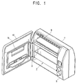
- an oven according to an embodiment of the present invention comprises: a main body 1 including an oven compartment 3 and a component compartment (not shown); a door 10 provided in the front of the main body 1 to open and close a front opening of the oven compartment 3 pivotally; an operation display panel 5 provided at a side of the front of the main body 1 to display an operation state of the main body 1; a pair of kneading drums 9 which is disposed in parallel each other in upper and lower parts of the oven compartment 3 which wind opposite ends of a mixing bag (not shown) filled with raw materials for bread in clockwise and counter-clockwise directions; and a baking tray 7 put in the oven compartment 3.
- the door 10 comprises: an inner cover 20 which is provided facing the oven compartment 3 and formed with a through opening 21 to show the oven compartment 3 therethrough; a transparent window 15 mounted in the through opening 21; a supporting member 30 supporting the transparent window 15 to the inner cover 20; and an outer cover 40 which is provided outside of the supporting member 31 and forms an outward appearance of the door 10.
- the transparent window 15 is preferably of a rectangular shape for being put in a window accommodating part 23 provided in the through opening 21 of the inner cover 20, but it may be of various shapes such as a circular, an oval or a polygonal shape according as designed.
- the transparent window 15 is preferably made of transparent or semitransparent glass which is capable of resisting heat of high temperature generated from the oven compartment 3, but it may be made of materials such as plastics.
- the inner cover 20 forms an inner part of the door 10 and is preferably made of metal plate resisting heat of high temperature, but it may be made of heat-resisting materials such as plastics.
- the through opening 21 formed in the inner cover 20 is of a rectangular shape.
- the through opening 21 may be of various shapes such as a circular or a polygonal shape according to the shape of the through opening 15.
- the window accommodating part 23 is provided in the through opening 21.
- the window accommodating part 23 is as shown in Figure 3, formed by being bent from the periphery of the through opening 21 toward the oven compartment 3 and then bent toward the center of the through opening 21, so that the transparent window 15 can be put in the bent part. That is, the window accommodating part 23 is preferably of an "L" shape (as shown).
- the supporting member 30 comprises preferably a plate part 31, which is combined with the inner cover 20 and the outer cover 40, respectively, through engaging means such as screws 35 and 45 and whose middle part is opened corresponding to the transparent window 15; a supporter 33 which is formed by being bended from the periphery of the opened middle part of the plate part 31 toward the inside of the oven compartment 3 and supports the transparent window 15 by contacting with the periphery of the transparent window 15 put in the window accommodating part 23; and a plurality of bosses 37 which project from the outer surface of the supporting member 30 and through which the screws 35 pass toward the outer cover 40.
- the supporter 33 supports the transparent window 15 by contacting the periphery of the transparent window 15 put in the window accommodating part 23, thereby preventing the transparent window 15 from being detached from the window accommodating part 23. It is preferable that the supporter 33 gives a predetermined pressure to the transparent window 15 against the window accommodating part 23 such that the transparent window 15 may not be broken.
- the pressure given to the transparent window 15 may be generated when the plate part 31 is combined with the inner cover 20 through the screws 35. Further, the intensity of the pressure can be controlled by controlling the intensity of the engaging force of the screw 35.
- the outer cover 40 forms an outward appearance of the door 10 and is provided with an observation window 41 placed corresponding to the transparent window 15.
- the outer cover 40 is preferably combined with the supporting member 30 by the screws 45.
- the outer cover 40 may be combined with the inner cover 20 by the screws 45. In this case, because the screws 45 are engaged with the inner cover 20 through the bosses 37 of the supporting member 30, the screws 35 are not necessary.
- the observation window 41 is preferably is made of transparent materials, so that the inside of the oven compartment 3 can be shown therethrough. Further, the observation window 41 may be made of the same material as that of the outer cover 40. Accordingly, the observation window 41 may be made of different material from that of the outer cover 40.
- the assembling process of the door 10 according to this embodiment of the present invention is to be described as follows: at first, the transparent window 15 of the inner cover 20 is put into the window accommodating part 23. Then, the supporting member 40 is combined with the inner cover 20, so that the transparent window 15 can be adhered to the window accommodating part 23 with the supporter 33 of the supporting member 31 being contacted with the periphery of the transparent window 15. Thereafter, the outer cover 40 is combined with the supporting member 30 so that the observation window 41 is placed corresponding to the transparent window 15.
- Heat-resisting elastic materials are preferably provided between the window accommodating part 23 and the transparent window 15 and between the supporter 33 and the transparent window 15.
- These heat-resisting elastic materials are preferably made of rubber, etc. which is capable of resisting heat of the high temperature generated from the oven compartment 3.
- the transparent window 15 given pressure by the supporter 33 can be prevented from being broken by means of the heat-resisting elastic materials provided between the window accommodating part 23 and the transparent window 15 and between the supporter 33 and the transparent window 15. Further, the leakage of heat generated from the oven compartment 3 can be reduced, by being sealed between the transparent window 15 and the through opening 21 of the inner cover 20 by means of the heat-resisting elastic materials.
- the door connected with the main body to open and close the oven compartment and comprises: the inner cover which is provided facing the oven compartment and formed with the through opening to show the oven compartment therethrough; the transparent window provided in the through opening of the inner cover; and the supporting member supporting the transparent window against the inner cover. Further, the window accommodating part is extended from the periphery of the through opening for putting the transparent window therein.
- a fixing means such as a jig and liquid sealant used for providing the transparent window to the door of the conventional oven are not necessary in the oven according to preferred embodiments of the present invention.
- assembly of the oven can be simplified, thereby enhancing the productivity.
Landscapes
- Engineering & Computer Science (AREA)
- Chemical & Material Sciences (AREA)
- Combustion & Propulsion (AREA)
- Mechanical Engineering (AREA)
- General Engineering & Computer Science (AREA)
- Baking, Grill, Roasting (AREA)
- Electric Ovens (AREA)
- Electric Stoves And Ranges (AREA)
- Food-Manufacturing Devices (AREA)
Abstract
- an inner cover (20) provided facing the oven compartment (3) and formed with a through opening to show the oven compartment (3) therethrough. The edges of the inner cover (20) in the periphery of the through opening are extended towards the inside of the oven compartment, thus forming a window accommodating part (23);
- a transparent window (15) provided in the through opening of the inner cover (20), bedded in said window accommodating part (23);
- and a supporting member (30) supporting the transparent window
(15) against the inner cover (20).
Thus, a fixing means such as a jig and liquid sealant used for providing the transparent window to the door during assembly of the conventional oven are not necessary according to the present invention.
Description
Claims (13)
- An oven provided with a main body (1) forming an oven compartment (3), and a door (10) in contact with the main body (1) to close and open the main body (1), the door (10) comprising:an inner cover (20) provided facing the oven compartment (3) and formed with a through opening (21) to show the oven compartment (3) therethrough; a transparent window (15) provided in the through opening (21) of the inner cover (20); and a supporting member (30) supporting the transparent window (15) against the inner cover (20), wherein a window accommodating part (23) is extended toward the inside of the oven compartment (3) from the periphery of the through opening (21) for accommodating the transparent window (15).
- The oven according to claim 1, wherein the window accommodating part (23) is bent so that the section thereof is of an "L" shape.
- The oven according to claim 1 or claim 2, wherein the supporting member (30) includes: a plate part (31) which is combined with the inner cover (20) and has an opening part corresponding to the transparent window (15); a supporter (33) which is extended from the periphery of the opening part of the plate part (31) toward the inside of the oven compartment (3) and supports the transparent window (15) against the window accommodating part (23) of the inner cover (20).
- The oven according to claim 3, wherein the supporter (33) gives a predetermined pressure to periphery of the transparent window (15).
- The oven according to claim 3 or claim 4, wherein heat-resisting elastic materials are provided between the window accommodating part (23) and the transparent window (15) and between the supporter (33) and the transparent window (15).
- The oven according to any preceding claims, wherein the door (10) further comprises an outer cover (40) which forms an outward appearance of the door (10) outside of the supporting member (30) and provided with an observation window placed in the accommodating part (23) corresponding to the inner cover (20).
- The oven according to claim 6, wherein the supporting member (30) is combined with the inner cover (20) and the outer cover (40), respectively.
- The oven of any preceding claims, wherein the window (15) comprises transparent or semi-transparent material.
- The oven of any preceding claims, wherein the window (15) is a rectangular shape.
- The oven of any preceding claims, wherein the supporting member (30) further comprises a plurality of bosses (37) which project from the outer surface of the supporting member (30) and through which screws (35,45) pass toward the inner cover (20).
- The oven of claim 4, wherein the pressure given to the window (15) is generated when the plate part (31) is combined with the inner cover (20) through screws.
- The oven of claim 6, wherein the outer cover (40) is combined with the inner cover (20) by screws.
- A method of assembling an oven door (10) comprising: placing a window (15) of an inner cover (20) into a window accommodating part (23) of an inner cover (20); attaching a supporting member (30) to the inner cover (20); adhering the window (15) to the window accommodating part (23) with a supporter (33) of the supporting member (30) being in contact with the periphery of the window (15); and combining an outer cover (40) with the supporting member (30) and the inner cover (20), respectively.
Applications Claiming Priority (2)
| Application Number | Priority Date | Filing Date | Title |
|---|---|---|---|
| KR1020030028987A KR20040096140A (en) | 2003-05-07 | 2003-05-07 | Oven |
| KR2003028987 | 2003-05-07 |
Publications (2)
| Publication Number | Publication Date |
|---|---|
| EP1475570A2 true EP1475570A2 (en) | 2004-11-10 |
| EP1475570A3 EP1475570A3 (en) | 2005-01-26 |
Family
ID=32985970
Family Applications (1)
| Application Number | Title | Priority Date | Filing Date |
|---|---|---|---|
| EP03257459A Withdrawn EP1475570A3 (en) | 2003-05-07 | 2003-11-26 | Oven door with window |
Country Status (5)
| Country | Link |
|---|---|
| US (1) | US20040226552A1 (en) |
| EP (1) | EP1475570A3 (en) |
| JP (2) | JP2004333113A (en) |
| KR (1) | KR20040096140A (en) |
| CN (1) | CN1547919A (en) |
Families Citing this family (3)
| Publication number | Priority date | Publication date | Assignee | Title |
|---|---|---|---|---|
| US8578925B2 (en) * | 2005-07-27 | 2013-11-12 | Whirlpool Corporation | Oven door assembly incorporating overlay member |
| KR102527643B1 (en) * | 2016-08-22 | 2023-05-03 | 삼성전자주식회사 | Cooking appliance, door for cooking appliance and method for manufacturing door of cooking appliance |
| USD980013S1 (en) * | 2019-06-28 | 2023-03-07 | Whirlpool Corporation | Cooking appliance |
Family Cites Families (10)
| Publication number | Priority date | Publication date | Assignee | Title |
|---|---|---|---|---|
| CA1070200A (en) * | 1968-02-07 | 1980-01-22 | Gsw Limited - Gsw Limitee | Shuttered oven-door window |
| US3881462A (en) * | 1974-05-01 | 1975-05-06 | Westinghouse Electric Corp | Windowed door for a heat cleaning oven |
| US3996710A (en) * | 1975-04-11 | 1976-12-14 | General Electric Company | Simplified oven door window |
| US4207863A (en) * | 1977-01-06 | 1980-06-17 | Les Industries Bfg Limitee | Door for pyrolytic range |
| US4127101A (en) * | 1977-05-23 | 1978-11-28 | GSW Limited -- GSW Limitee | Windowed oven door having shield raising and door locking system |
| US4390767A (en) * | 1981-01-28 | 1983-06-28 | Amana Refrigeration, Inc. | Windowed and choked combination oven door |
| US4606324A (en) * | 1984-12-28 | 1986-08-19 | Mills Products, Inc. | Oven door |
| US5881710A (en) * | 1998-05-21 | 1999-03-16 | Whirlpool Corporation | Oven door and method of assembly therefor |
| DE19853758C2 (en) * | 1998-11-21 | 2001-10-18 | Ege Elektro Gmbh | Oven door with window and operating handle |
| EP1106932B1 (en) * | 1999-11-30 | 2004-04-28 | AEG Hausgeräte GmbH | Oven door with supporting elements made of plastic material |
-
2003
- 2003-05-07 KR KR1020030028987A patent/KR20040096140A/en not_active Withdrawn
- 2003-11-14 CN CNA2003101162005A patent/CN1547919A/en active Pending
- 2003-11-26 EP EP03257459A patent/EP1475570A3/en not_active Withdrawn
-
2004
- 2004-03-19 US US10/804,012 patent/US20040226552A1/en not_active Abandoned
- 2004-03-30 JP JP2004101448A patent/JP2004333113A/en active Pending
- 2004-03-30 JP JP2004101342A patent/JP3792233B2/en not_active Expired - Fee Related
Also Published As
| Publication number | Publication date |
|---|---|
| KR20040096140A (en) | 2004-11-16 |
| CN1547919A (en) | 2004-11-24 |
| JP2004333113A (en) | 2004-11-25 |
| JP3792233B2 (en) | 2006-07-05 |
| EP1475570A3 (en) | 2005-01-26 |
| US20040226552A1 (en) | 2004-11-18 |
| JP2004329891A (en) | 2004-11-25 |
Similar Documents
| Publication | Publication Date | Title |
|---|---|---|
| US7819113B2 (en) | Door assembly for a cooking apparatus | |
| KR101206813B1 (en) | Metal panel and the manufacturing method thereof and cooking Device using the metal panel | |
| US10801732B2 (en) | Control console assembly for a cooking appliance | |
| EP2868981B1 (en) | A door for a domestic appliance | |
| EP3404332B1 (en) | Cooking appliance | |
| EP1475570A2 (en) | Oven door with window | |
| EP1503613A1 (en) | Microwave oven | |
| WO2020133251A1 (en) | Transparent lcd solution for microwave oven | |
| JP2000274694A (en) | Cooking device | |
| KR100641433B1 (en) | Electric oven | |
| EP1489362A2 (en) | Door for household appliance | |
| EP1369645B1 (en) | Microwave oven with saucer holders | |
| EP1474977A1 (en) | Bread maker and oven for bread maker | |
| JP7713501B2 (en) | heating cooker | |
| KR100485575B1 (en) | Microwave Oven | |
| CN208463641U (en) | Cooking apparatus | |
| CN211533884U (en) | Control assembly and cooking utensil with same | |
| US20040031792A1 (en) | Microwave oven | |
| EP1474975A2 (en) | Bread maker | |
| KR200349861Y1 (en) | Door for microwave oven | |
| KR200262394Y1 (en) | Microwave oven | |
| KR20070053927A (en) | Electric oven | |
| KR20010056763A (en) | structure for oven-door in gas oven range | |
| KR20040096136A (en) | Oven for baking bread | |
| WO2006090347A2 (en) | A cooking device |
Legal Events
| Date | Code | Title | Description |
|---|---|---|---|
| PUAI | Public reference made under article 153(3) epc to a published international application that has entered the european phase |
Free format text: ORIGINAL CODE: 0009012 |
|
| 17P | Request for examination filed |
Effective date: 20031208 |
|
| AK | Designated contracting states |
Kind code of ref document: A2 Designated state(s): AT BE BG CH CY CZ DE DK EE ES FI FR GB GR HU IE IT LI LU MC NL PT RO SE SI SK TR |
|
| AX | Request for extension of the european patent |
Extension state: AL LT LV MK |
|
| PUAL | Search report despatched |
Free format text: ORIGINAL CODE: 0009013 |
|
| AK | Designated contracting states |
Kind code of ref document: A3 Designated state(s): AT BE BG CH CY CZ DE DK EE ES FI FR GB GR HU IE IT LI LU MC NL PT RO SE SI SK TR |
|
| AX | Request for extension of the european patent |
Extension state: AL LT LV MK |
|
| AKX | Designation fees paid |
Designated state(s): DE FR GB SE |
|
| 17Q | First examination report despatched |
Effective date: 20080117 |
|
| STAA | Information on the status of an ep patent application or granted ep patent |
Free format text: STATUS: THE APPLICATION IS DEEMED TO BE WITHDRAWN |
|
| 18D | Application deemed to be withdrawn |
Effective date: 20080528 |