EP1475521A1 - Exhaust gas decontamination system and method of exhaust gas decontamination - Google Patents
Exhaust gas decontamination system and method of exhaust gas decontamination Download PDFInfo
- Publication number
- EP1475521A1 EP1475521A1 EP03703302A EP03703302A EP1475521A1 EP 1475521 A1 EP1475521 A1 EP 1475521A1 EP 03703302 A EP03703302 A EP 03703302A EP 03703302 A EP03703302 A EP 03703302A EP 1475521 A1 EP1475521 A1 EP 1475521A1
- Authority
- EP
- European Patent Office
- Prior art keywords
- exhaust gas
- control operation
- rich
- catalyst
- nox
- Prior art date
- Legal status (The legal status is an assumption and is not a legal conclusion. Google has not performed a legal analysis and makes no representation as to the accuracy of the status listed.)
- Granted
Links
Images







Classifications
-
- F—MECHANICAL ENGINEERING; LIGHTING; HEATING; WEAPONS; BLASTING
- F01—MACHINES OR ENGINES IN GENERAL; ENGINE PLANTS IN GENERAL; STEAM ENGINES
- F01N—GAS-FLOW SILENCERS OR EXHAUST APPARATUS FOR MACHINES OR ENGINES IN GENERAL; GAS-FLOW SILENCERS OR EXHAUST APPARATUS FOR INTERNAL-COMBUSTION ENGINES
- F01N3/00—Exhaust or silencing apparatus having means for purifying, rendering innocuous, or otherwise treating exhaust
- F01N3/08—Exhaust or silencing apparatus having means for purifying, rendering innocuous, or otherwise treating exhaust for rendering innocuous
- F01N3/0807—Exhaust or silencing apparatus having means for purifying, rendering innocuous, or otherwise treating exhaust for rendering innocuous by using absorbents or adsorbents
- F01N3/0814—Exhaust or silencing apparatus having means for purifying, rendering innocuous, or otherwise treating exhaust for rendering innocuous by using absorbents or adsorbents combined with catalytic converters, e.g. NOx absorption/storage reduction catalysts
-
- F—MECHANICAL ENGINEERING; LIGHTING; HEATING; WEAPONS; BLASTING
- F01—MACHINES OR ENGINES IN GENERAL; ENGINE PLANTS IN GENERAL; STEAM ENGINES
- F01N—GAS-FLOW SILENCERS OR EXHAUST APPARATUS FOR MACHINES OR ENGINES IN GENERAL; GAS-FLOW SILENCERS OR EXHAUST APPARATUS FOR INTERNAL-COMBUSTION ENGINES
- F01N3/00—Exhaust or silencing apparatus having means for purifying, rendering innocuous, or otherwise treating exhaust
- F01N3/08—Exhaust or silencing apparatus having means for purifying, rendering innocuous, or otherwise treating exhaust for rendering innocuous
- F01N3/0807—Exhaust or silencing apparatus having means for purifying, rendering innocuous, or otherwise treating exhaust for rendering innocuous by using absorbents or adsorbents
- F01N3/0828—Exhaust or silencing apparatus having means for purifying, rendering innocuous, or otherwise treating exhaust for rendering innocuous by using absorbents or adsorbents characterised by the absorbed or adsorbed substances
- F01N3/0842—Nitrogen oxides
-
- F—MECHANICAL ENGINEERING; LIGHTING; HEATING; WEAPONS; BLASTING
- F01—MACHINES OR ENGINES IN GENERAL; ENGINE PLANTS IN GENERAL; STEAM ENGINES
- F01N—GAS-FLOW SILENCERS OR EXHAUST APPARATUS FOR MACHINES OR ENGINES IN GENERAL; GAS-FLOW SILENCERS OR EXHAUST APPARATUS FOR INTERNAL-COMBUSTION ENGINES
- F01N3/00—Exhaust or silencing apparatus having means for purifying, rendering innocuous, or otherwise treating exhaust
- F01N3/08—Exhaust or silencing apparatus having means for purifying, rendering innocuous, or otherwise treating exhaust for rendering innocuous
- F01N3/10—Exhaust or silencing apparatus having means for purifying, rendering innocuous, or otherwise treating exhaust for rendering innocuous by thermal or catalytic conversion of noxious components of exhaust
- F01N3/24—Exhaust or silencing apparatus having means for purifying, rendering innocuous, or otherwise treating exhaust for rendering innocuous by thermal or catalytic conversion of noxious components of exhaust characterised by constructional aspects of converting apparatus
- F01N3/28—Construction of catalytic reactors
- F01N3/2803—Construction of catalytic reactors characterised by structure, by material or by manufacturing of catalyst support
- F01N3/2825—Ceramics
- F01N3/2828—Ceramic multi-channel monoliths, e.g. honeycombs
-
- F—MECHANICAL ENGINEERING; LIGHTING; HEATING; WEAPONS; BLASTING
- F02—COMBUSTION ENGINES; HOT-GAS OR COMBUSTION-PRODUCT ENGINE PLANTS
- F02D—CONTROLLING COMBUSTION ENGINES
- F02D41/00—Electrical control of supply of combustible mixture or its constituents
- F02D41/0002—Controlling intake air
-
- F—MECHANICAL ENGINEERING; LIGHTING; HEATING; WEAPONS; BLASTING
- F02—COMBUSTION ENGINES; HOT-GAS OR COMBUSTION-PRODUCT ENGINE PLANTS
- F02D—CONTROLLING COMBUSTION ENGINES
- F02D41/00—Electrical control of supply of combustible mixture or its constituents
- F02D41/02—Circuit arrangements for generating control signals
- F02D41/021—Introducing corrections for particular conditions exterior to the engine
- F02D41/0235—Introducing corrections for particular conditions exterior to the engine in relation with the state of the exhaust gas treating apparatus
- F02D41/024—Introducing corrections for particular conditions exterior to the engine in relation with the state of the exhaust gas treating apparatus to increase temperature of the exhaust gas treating apparatus
- F02D41/0245—Introducing corrections for particular conditions exterior to the engine in relation with the state of the exhaust gas treating apparatus to increase temperature of the exhaust gas treating apparatus by increasing temperature of the exhaust gas leaving the engine
-
- F—MECHANICAL ENGINEERING; LIGHTING; HEATING; WEAPONS; BLASTING
- F02—COMBUSTION ENGINES; HOT-GAS OR COMBUSTION-PRODUCT ENGINE PLANTS
- F02D—CONTROLLING COMBUSTION ENGINES
- F02D41/00—Electrical control of supply of combustible mixture or its constituents
- F02D41/02—Circuit arrangements for generating control signals
- F02D41/021—Introducing corrections for particular conditions exterior to the engine
- F02D41/0235—Introducing corrections for particular conditions exterior to the engine in relation with the state of the exhaust gas treating apparatus
- F02D41/027—Introducing corrections for particular conditions exterior to the engine in relation with the state of the exhaust gas treating apparatus to purge or regenerate the exhaust gas treating apparatus
- F02D41/0275—Introducing corrections for particular conditions exterior to the engine in relation with the state of the exhaust gas treating apparatus to purge or regenerate the exhaust gas treating apparatus the exhaust gas treating apparatus being a NOx trap or adsorbent
-
- F—MECHANICAL ENGINEERING; LIGHTING; HEATING; WEAPONS; BLASTING
- F02—COMBUSTION ENGINES; HOT-GAS OR COMBUSTION-PRODUCT ENGINE PLANTS
- F02D—CONTROLLING COMBUSTION ENGINES
- F02D41/00—Electrical control of supply of combustible mixture or its constituents
- F02D41/02—Circuit arrangements for generating control signals
- F02D41/14—Introducing closed-loop corrections
- F02D41/1438—Introducing closed-loop corrections using means for determining characteristics of the combustion gases; Sensors therefor
- F02D41/1439—Introducing closed-loop corrections using means for determining characteristics of the combustion gases; Sensors therefor characterised by the position of the sensor
- F02D41/1441—Plural sensors
-
- F—MECHANICAL ENGINEERING; LIGHTING; HEATING; WEAPONS; BLASTING
- F02—COMBUSTION ENGINES; HOT-GAS OR COMBUSTION-PRODUCT ENGINE PLANTS
- F02D—CONTROLLING COMBUSTION ENGINES
- F02D41/00—Electrical control of supply of combustible mixture or its constituents
- F02D41/02—Circuit arrangements for generating control signals
- F02D41/14—Introducing closed-loop corrections
- F02D41/1438—Introducing closed-loop corrections using means for determining characteristics of the combustion gases; Sensors therefor
- F02D41/1444—Introducing closed-loop corrections using means for determining characteristics of the combustion gases; Sensors therefor characterised by the characteristics of the combustion gases
- F02D41/146—Introducing closed-loop corrections using means for determining characteristics of the combustion gases; Sensors therefor characterised by the characteristics of the combustion gases the characteristics being an NOx content or concentration
-
- F—MECHANICAL ENGINEERING; LIGHTING; HEATING; WEAPONS; BLASTING
- F02—COMBUSTION ENGINES; HOT-GAS OR COMBUSTION-PRODUCT ENGINE PLANTS
- F02D—CONTROLLING COMBUSTION ENGINES
- F02D41/00—Electrical control of supply of combustible mixture or its constituents
- F02D41/30—Controlling fuel injection
- F02D41/38—Controlling fuel injection of the high pressure type
- F02D41/40—Controlling fuel injection of the high pressure type with means for controlling injection timing or duration
- F02D41/402—Multiple injections
-
- F—MECHANICAL ENGINEERING; LIGHTING; HEATING; WEAPONS; BLASTING
- F02—COMBUSTION ENGINES; HOT-GAS OR COMBUSTION-PRODUCT ENGINE PLANTS
- F02M—SUPPLYING COMBUSTION ENGINES IN GENERAL WITH COMBUSTIBLE MIXTURES OR CONSTITUENTS THEREOF
- F02M26/00—Engine-pertinent apparatus for adding exhaust gases to combustion-air, main fuel or fuel-air mixture, e.g. by exhaust gas recirculation [EGR] systems
- F02M26/02—EGR systems specially adapted for supercharged engines
- F02M26/04—EGR systems specially adapted for supercharged engines with a single turbocharger
- F02M26/05—High pressure loops, i.e. wherein recirculated exhaust gas is taken out from the exhaust system upstream of the turbine and reintroduced into the intake system downstream of the compressor
-
- F—MECHANICAL ENGINEERING; LIGHTING; HEATING; WEAPONS; BLASTING
- F02—COMBUSTION ENGINES; HOT-GAS OR COMBUSTION-PRODUCT ENGINE PLANTS
- F02M—SUPPLYING COMBUSTION ENGINES IN GENERAL WITH COMBUSTIBLE MIXTURES OR CONSTITUENTS THEREOF
- F02M26/00—Engine-pertinent apparatus for adding exhaust gases to combustion-air, main fuel or fuel-air mixture, e.g. by exhaust gas recirculation [EGR] systems
- F02M26/13—Arrangement or layout of EGR passages, e.g. in relation to specific engine parts or for incorporation of accessories
- F02M26/22—Arrangement or layout of EGR passages, e.g. in relation to specific engine parts or for incorporation of accessories with coolers in the recirculation passage
- F02M26/23—Layout, e.g. schematics
-
- F—MECHANICAL ENGINEERING; LIGHTING; HEATING; WEAPONS; BLASTING
- F01—MACHINES OR ENGINES IN GENERAL; ENGINE PLANTS IN GENERAL; STEAM ENGINES
- F01N—GAS-FLOW SILENCERS OR EXHAUST APPARATUS FOR MACHINES OR ENGINES IN GENERAL; GAS-FLOW SILENCERS OR EXHAUST APPARATUS FOR INTERNAL-COMBUSTION ENGINES
- F01N2560/00—Exhaust systems with means for detecting or measuring exhaust gas components or characteristics
- F01N2560/02—Exhaust systems with means for detecting or measuring exhaust gas components or characteristics the means being an exhaust gas sensor
- F01N2560/026—Exhaust systems with means for detecting or measuring exhaust gas components or characteristics the means being an exhaust gas sensor for measuring or detecting NOx
-
- F—MECHANICAL ENGINEERING; LIGHTING; HEATING; WEAPONS; BLASTING
- F02—COMBUSTION ENGINES; HOT-GAS OR COMBUSTION-PRODUCT ENGINE PLANTS
- F02B—INTERNAL-COMBUSTION PISTON ENGINES; COMBUSTION ENGINES IN GENERAL
- F02B29/00—Engines characterised by provision for charging or scavenging not provided for in groups F02B25/00, F02B27/00 or F02B33/00 - F02B39/00; Details thereof
- F02B29/04—Cooling of air intake supply
- F02B29/0406—Layout of the intake air cooling or coolant circuit
-
- F—MECHANICAL ENGINEERING; LIGHTING; HEATING; WEAPONS; BLASTING
- F02—COMBUSTION ENGINES; HOT-GAS OR COMBUSTION-PRODUCT ENGINE PLANTS
- F02B—INTERNAL-COMBUSTION PISTON ENGINES; COMBUSTION ENGINES IN GENERAL
- F02B37/00—Engines characterised by provision of pumps driven at least for part of the time by exhaust
-
- F—MECHANICAL ENGINEERING; LIGHTING; HEATING; WEAPONS; BLASTING
- F02—COMBUSTION ENGINES; HOT-GAS OR COMBUSTION-PRODUCT ENGINE PLANTS
- F02D—CONTROLLING COMBUSTION ENGINES
- F02D11/00—Arrangements for, or adaptations to, non-automatic engine control initiation means, e.g. operator initiated
- F02D11/06—Arrangements for, or adaptations to, non-automatic engine control initiation means, e.g. operator initiated characterised by non-mechanical control linkages, e.g. fluid control linkages or by control linkages with power drive or assistance
- F02D11/10—Arrangements for, or adaptations to, non-automatic engine control initiation means, e.g. operator initiated characterised by non-mechanical control linkages, e.g. fluid control linkages or by control linkages with power drive or assistance of the electric type
- F02D11/105—Arrangements for, or adaptations to, non-automatic engine control initiation means, e.g. operator initiated characterised by non-mechanical control linkages, e.g. fluid control linkages or by control linkages with power drive or assistance of the electric type characterised by the function converting demand to actuation, e.g. a map indicating relations between an accelerator pedal position and throttle valve opening or target engine torque
-
- F—MECHANICAL ENGINEERING; LIGHTING; HEATING; WEAPONS; BLASTING
- F02—COMBUSTION ENGINES; HOT-GAS OR COMBUSTION-PRODUCT ENGINE PLANTS
- F02D—CONTROLLING COMBUSTION ENGINES
- F02D2200/00—Input parameters for engine control
- F02D2200/02—Input parameters for engine control the parameters being related to the engine
- F02D2200/08—Exhaust gas treatment apparatus parameters
- F02D2200/0806—NOx storage amount, i.e. amount of NOx stored on NOx trap
-
- F—MECHANICAL ENGINEERING; LIGHTING; HEATING; WEAPONS; BLASTING
- F02—COMBUSTION ENGINES; HOT-GAS OR COMBUSTION-PRODUCT ENGINE PLANTS
- F02D—CONTROLLING COMBUSTION ENGINES
- F02D2250/00—Engine control related to specific problems or objectives
- F02D2250/18—Control of the engine output torque
-
- F—MECHANICAL ENGINEERING; LIGHTING; HEATING; WEAPONS; BLASTING
- F02—COMBUSTION ENGINES; HOT-GAS OR COMBUSTION-PRODUCT ENGINE PLANTS
- F02D—CONTROLLING COMBUSTION ENGINES
- F02D41/00—Electrical control of supply of combustible mixture or its constituents
- F02D41/0025—Controlling engines characterised by use of non-liquid fuels, pluralities of fuels, or non-fuel substances added to the combustible mixtures
- F02D41/0047—Controlling exhaust gas recirculation [EGR]
- F02D41/005—Controlling exhaust gas recirculation [EGR] according to engine operating conditions
- F02D41/0055—Special engine operating conditions, e.g. for regeneration of exhaust gas treatment apparatus
-
- F—MECHANICAL ENGINEERING; LIGHTING; HEATING; WEAPONS; BLASTING
- F02—COMBUSTION ENGINES; HOT-GAS OR COMBUSTION-PRODUCT ENGINE PLANTS
- F02M—SUPPLYING COMBUSTION ENGINES IN GENERAL WITH COMBUSTIBLE MIXTURES OR CONSTITUENTS THEREOF
- F02M26/00—Engine-pertinent apparatus for adding exhaust gases to combustion-air, main fuel or fuel-air mixture, e.g. by exhaust gas recirculation [EGR] systems
- F02M26/13—Arrangement or layout of EGR passages, e.g. in relation to specific engine parts or for incorporation of accessories
- F02M26/14—Arrangement or layout of EGR passages, e.g. in relation to specific engine parts or for incorporation of accessories in relation to the exhaust system
- F02M26/15—Arrangement or layout of EGR passages, e.g. in relation to specific engine parts or for incorporation of accessories in relation to the exhaust system in relation to engine exhaust purifying apparatus
-
- Y—GENERAL TAGGING OF NEW TECHNOLOGICAL DEVELOPMENTS; GENERAL TAGGING OF CROSS-SECTIONAL TECHNOLOGIES SPANNING OVER SEVERAL SECTIONS OF THE IPC; TECHNICAL SUBJECTS COVERED BY FORMER USPC CROSS-REFERENCE ART COLLECTIONS [XRACs] AND DIGESTS
- Y02—TECHNOLOGIES OR APPLICATIONS FOR MITIGATION OR ADAPTATION AGAINST CLIMATE CHANGE
- Y02T—CLIMATE CHANGE MITIGATION TECHNOLOGIES RELATED TO TRANSPORTATION
- Y02T10/00—Road transport of goods or passengers
- Y02T10/10—Internal combustion engine [ICE] based vehicles
- Y02T10/12—Improving ICE efficiencies
-
- Y—GENERAL TAGGING OF NEW TECHNOLOGICAL DEVELOPMENTS; GENERAL TAGGING OF CROSS-SECTIONAL TECHNOLOGIES SPANNING OVER SEVERAL SECTIONS OF THE IPC; TECHNICAL SUBJECTS COVERED BY FORMER USPC CROSS-REFERENCE ART COLLECTIONS [XRACs] AND DIGESTS
- Y02—TECHNOLOGIES OR APPLICATIONS FOR MITIGATION OR ADAPTATION AGAINST CLIMATE CHANGE
- Y02T—CLIMATE CHANGE MITIGATION TECHNOLOGIES RELATED TO TRANSPORTATION
- Y02T10/00—Road transport of goods or passengers
- Y02T10/10—Internal combustion engine [ICE] based vehicles
- Y02T10/40—Engine management systems
Definitions
- the present invention concerns an exhaust gas purifying system for purifying nitrogen oxides in an exhaust gas, provided with a nitrogen oxides occlusion reduction type catalyst in an internal combustion engine such as a diesel engine, and a method of exhaust gas purification.
- NOx nitrogen oxides
- NOx occlusion reduction type catalyst containing NOx occluding substance is used or under consideration to be used for purifying an exhaust gas from a lean-burn gasoline engine or a diesel engine.
- this NOx occlusion reduction type catalyst can purify NOx even if oxygen (O 2 , hereinafter) exists in an exhaust gas.
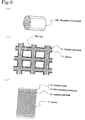
- Fig. 9 shows the structure of the NOx occlusion reduction type catalyst 70, while Fig. 10 and Fig. 11 show the disposition of active metal on the support layer surface and the mechanism of occlusion, release and removal of NOx.
- the NOx occlusion reduction type catalyst 70 shown in Fig. 9 is formed as a monolithic honeycomb 70M provided with a number of polygonal (quadrangular in Fig. 9) cells 70S on a catalyst support 71 of structural material made of codierite, stainless steel and the like.
- the inner wall of the cell 70S presenting a large surface area as a whole is coated with a catalyst coat layer (support layer) 74 formed with a porous coating material such as zeolite or alumina (Al 2 O 3 ) and silica in order to increase the surface area.
- a catalyst coat layer (support layer) 74 formed with a porous coating material such as zeolite or alumina (Al 2 O 3 ) and silica in order to increase the surface area.
- a catalyst metal 72 and a NOx occluding substance (R) 73 are supported by the catalyst coat layer 74.
- This catalyst metal 72 is formed with a precious metal such as platinum (Pt) having an oxidation function, while the NOx occluding substance (R) 33 is formed with one or several of alkali metals such as potassium (K), alkaline-earth metals such as barium (Ba, hereinafter) or rare-earth such as lanthanum (La) having NOx occlusion and release function.
- a precious metal such as platinum (Pt) having an oxidation function
- the NOx occluding substance (R) 33 is formed with one or several of alkali metals such as potassium (K), alkaline-earth metals such as barium (Ba, hereinafter) or rare-earth such as lanthanum (La) having NOx occlusion and release function.
- Fig. 10 shows the mechanism of purification by NOx occlusion with the NOx occlusion reduction type catalyst 70, under an exhaust gas condition where O 2 is contained in the exhaust gas such as the exhaust condition in normal operation of a diesel engine, a lean-burn gasoline engine or the likes.
- a nitrogen monoxide (NO, hereinafter) in the exhaust gas reacts with O 2 in the exhaust gas to be oxidized and turns into nitrogen dioxide (NO 2 , hereinafter) by the catalysis of the catalyst metal 72.
- the NOx occluding substance (R) 73 such as Ba occludes the NO 2 in a form of nitrate (for instance, Ba(NO 3 ) 2 ) and consequently the NOx in the exhaust gas is purified.
- the engine operation condition is changed to generate a rich state exhaust gas (exhaust gas of a rich air/fuel ratio) without O 2 and with a high carbon monoxide (CO, hereinafter) concentration and a high exhaust temperature, then the exhaust gas is sent to the NOx occlusion reduction type catalyst.
- a rich state exhaust gas exhaust gas of a rich air/fuel ratio
- CO carbon monoxide
- the NOx occluding substance (R) 73 that has occluded NOx releases NO 2 , as the nitrite returns into the original form such as Ba.
- the released NO 2 is reduced to water, (H 2 O, hereinafter), carbon dioxide (CO 2 , hereinafter) and nitrogen (N 2 , hereinafter) and purified, reacting with a CO, a hydrocarbon (HC, hereinafter), a hydrogen (H 2 , herein after) and so on in the exhaust gas as the reducer by the catalysis of the catalyst metal 72.
- Fig. 12 shows the NOx purifying performance of a NOx occlusion reduction type catalyst in an exhaust gas purifying system generating an exhaust gas which is in a rich-burn state by using a conventional EGR. According to the Fig. 12, it can be understood that a peak of high NOx concentration appears at the beginning of the regeneration where a rich-burn operation for regenerating a NOx occlusion reduction type catalyst starts by the rich-burn (rich state) accompanied by EGR and that the NOx removal efficiency significantly lowers.
- the present invention is devised to solve the aforementioned problems and the object is to provide an exhaust gas purifying system and a method of an exhaust gas purification capable of removing sufficiently NOx released from a NOx occlusion reduction type catalyst and achieving a high NOx removal efficiency, even in a rich-burn accompanied by EGR by executing a catalyst activation control operation to heat up the catalyst surface immediately before the rich-burn accompanied by EGR starts when regenerating a NOx occlusion reduction type catalyst.
- the exhaust gas purifying system for achieving the aforementioned object is composed as follows.
- An exhaust gas purifying system provided with a NOx occlusion reduction type catalyst having a catalyst metal and a NOx occluding substance in an exhaust passage of an engine and a control unit comprising a normal control operation means, a regeneration control initiation judging means for detecting a regeneration control initiation timing for said NOx occlusion reduction type catalyst, and a rich-burn control operation means capable of lowering the concentration of oxygen in the exhaust gas; wherein said rich-burn control operation means executes the rich-burn control operation for generating an exhaust gas which is in a fuel-rich state by recirculating EGR gas and said control unit comprises a catalyst activation control operation means for executing a control operation for activating said catalyst metal immediately before performing said rich-burn control operation.
- the catalyst metal can be formed with those having an oxidation reduction catalytic function such as platinum, while the NOx occluding substance can be formed with any one or combination of alkali metals such as potassium (K), sodium (Na), lithium (L), cesium (Cs), alkaline-earth metals such as barium (Ba), calcium (Ca), and rare earths such as lanthanum (La), yttrium (Y).
- alkali metals such as potassium (K), sodium (Na), lithium (L), cesium (Cs), alkaline-earth metals such as barium (Ba), calcium (Ca), and rare earths such as lanthanum (La), yttrium (Y).
- the operation where the air/fuel ratio state in the exhaust gas becomes rich is not necessarily a rich-burn in the cylinder bore, but it may be a operation where the air/fuel ratio in the exhaust gas flowing in the NOx occlusion reduction type catalyst becomes the state of rich, near the theoretical air/fuel ratio or where the fuel quantity exceeds the theoretical air/fuel ratio.
- this composition it is possible to cut down the fuel consumption during a rich-burn, as EGR gas is recirculated when the rich-burn is executed for regenerating a NOx occlusion reduction type catalyst and, moreover, the NOx released from the NOx occluding substance is removed sufficiently, because the control for activating the catalyst metal is performed immediately before the rich-burn accompanied by EGR, and the rich-burn is performed immediately after the catalyst is activated.
- the catalyst surface temperature rises efficiently, as the exhaust gas temperature can be elevated with less quantity of fuel.
- no EGR is performed with the EGR valve totally closed in order to raise the exhaust gas temperature as high as possible.
- the multi-stage injection and the early injection accelerate the mixing of fuel and gas in the cylinder, permitting a smokeless burning to be realized.
- the reducer occluding substance can be composed with a substance such as a zeolite or the likes that occludes HC and CO at a low temperature and releasing at a high temperature. And providing with this reducer occluding substance, the reducer occluding substance purifies the exhaust gas by occluding HC and CO in the exhaust gas during a normal operation, and moreover, during a regeneration control operation of a NOx occlusion reduction type catalyst, occluded HC and CO are released to be the reducer of the NOx released at the same time and the NOx can be reduced.
- a substance such as a zeolite or the likes that occludes HC and CO at a low temperature and releasing at a high temperature.
- the method of exhaust gas purification in the aforementioned exhaust gas purifying system is composed as follows and can provide functional effects similar to those mentioned above.
- the exhaust gas purifying system provided with the NOx occlusion reduction type catalyst and the method of exhaust gas purification of the present invention since a rich burning accompanied by EGR is performed after the NOx occlusion reduction type catalyst has heated up to a high temperature to be activated preliminarily by a catalyst activation control operation such as a burning in the nearly stoichiometric air/fuel ratio, before regenerating the NOx occlusion reduction type catalyst, it is possible to prevent the surface temperature of the NOx occlusion reduction type catalyst from being lowered by the rich-burn accompanied by EGR and the catalyst activity from being deteriorated by the surface temperature fall.
- a NOx can be reduced sufficiently, even if a rich-burn accompanied by EGR is performed under a regeneration control operation, and the NOx purifying performance can be improved, curbing a deterioration in fuel efficiency by a regeneration control.
- Fig. 1 shows the composition diagram of an engine 2 and an engine exhaust system of an exhaust gas purifying system 1 provided with a NOx occlusion reduction type catalyst 30 by an example of a diesel engine
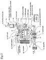
- Fig. 2 shows the detail of the engine system part of Fig. 1.
- an air purifier 21, a compressor 5a of a turbocharger 5, an intercooler 22 and a throttle butterfly (intake throttling valve) 23 are arranged from the upstream side in an intake passage 2 of an engine 10, while an exhaust gas temperature sensor 51, a turbine 5b of a turbocharger 5, an excess air factor ( ⁇ ) sensor 52, an inlet side NOx sensor 53, a NOx occlusion reduction type catalyst 30, an exit side NOx sensor 54 and a silencer 31(Fig.1) are arranged from the upstream side in an exhaust passage 3.
- an EGR passage 4 provided with an EGR cooler 41 and an EGR valve 42 is connected from an exhaust manifold 12 to the intake passage 2 on the downstream side of the throttle butterfly 23.
- a common-rail injection system 6 for a fuel injection of the engine 10 and an electronic control apparatus (electronic control box) 7 for controlling the whole engine called ECU (engine control unit) are installed.
- variable capacity type turbo VVS
- turbo with waist gate any of a variable capacity type turbo (VGS), a turbo with waist gate or an ordinary turbo may be used as the turbocharger 5, in case of using the variable capacity type turbo (VGS) or the turbo with waist gate, the variable nozzle and the waist gate are also controlled by the electronic control apparatus 7.
- an air A passes through the air purifier 21 to be supercharged by the compressor 5a of the turbocharger 5 and then to be cooled by the intercooler 22, subsequently passes through the throttle butterfly 23 to be supplied in the cylinder from the intake manifold 11 of the engine 10.
- the flow of the intake is adjusted by the throttle butterfly 23 which is controlled by the electronic control apparatus 7.
- an exhaust gas G gets out of the exhaust manifold 12 to drive the turbine 5b of the turbocharger 5, subsequently passes through the NOx occlusion reduction type catalyst 30 to be a purified exhaust gas Gc, and it is discharged from a tail pipe 32 (Fig. 1) after passing through the silencer 31 (Fig. 1).
- an EGR gas Ge which is a part of the exhaust gas G, passes through the EGR valve 42 after being cooled by the EGR cooler 41 and enters the intake passage 2 to circulate again.
- ON/OFF and gas flow adjustment are performed by the EGR valve 42.
- Fig. 3 shows the wall surface structure of the NOx occlusion reduction type catalyst 30.
- This NOx occlusion reduction type catalyst 30 is formed with a monolithic honeycomb 30M composed of a support body 31 such as a ⁇ alumina, and the surface inside of cells 30S of the monolithic honeycomb 30M is coated with a reducer occluding substance 34 which is formed with zeolite or the likes, and a catalytic metal 32 and a NOx occluding substance 33 are supported on the surface.
- the catalytic metal 32 is formed with platinum (Pt) or others having oxidation activity in a temperature range higher than the activity initiation temperature.
- the activity initiation temperature of platinum is about from 150 °C to 200 °C.
- the NOx occluding substance 33 is formed with alkali metals such as potassium (K), sodium (Na), lithium (L), cesium (Cs), alkaline-earth metals such as barium (Ba), calcium (Ca) and rare earth such as lanthanum (La), yttrium (Y), and occludes NOx when the O 2 concentration in the gas is high, and releases NOx when the O 2 concentration in the gas is low.
- alkali metals such as potassium (K), sodium (Na), lithium (L), cesium (Cs), alkaline-earth metals such as barium (Ba), calcium (Ca) and rare earth such as lanthanum (La), yttrium (Y), and occludes NOx when the O 2 concentration in the gas is high, and releases NOx when the O 2 concentration in the gas is low.
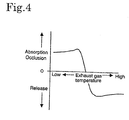
- the reducer occluding substance 34 formed with zeolite or others absorbs or occludes reducers such as HC or CO at a low temperature, and releases at a high temperature.
- Fig. 4 shows the relation (temperature characteristics) of absorption, occlusion and release of HC or GO in respect to the catalyst temperature of the reducer occluding substance 34.
- the method of the exhaust gas purification is performed by the exhaust gas purifying system 1 wherein the control means of the exhaust gas purifying system 1 comprises every means as shown in Fig. 5.
- the control means is composed of a normal control operation means C10, a regeneration control initiation judging means C20, a catalyst activation control operation means C30 and a rich-burn control operation means C40.
- the normal control operation means C10 is a control means for performing a normal lean-burn operation
- the regeneration control initiation judging means C20 is for judging whether the NOx occluding capacity of the NOx occlusion reduction type catalyst 30 has saturated or not.
- the rich-burn control operation means C40 is composed of a large quantity EGR regeneration control means C41 and the large quantity EGR regeneration control means C41 is a means to release NOx from the NOx occluding substance 30 by generating an exhaust gas near zero of O 2 concentration and to reduce the released NOx at the same time.
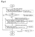
- the method of exhaust gas purification is executed according to the regeneration control flow of the NOx occlusion reduction type catalyst as illustrated in Fig. 6 to Fig. 8, and in the step S10, a normal lean-burn operation is executed by the normal control operation means C10, and when the regeneration control operation for regenerating the NOx occlusion reduction type catalyst 30 is judged to be necessary by the regeneration control initiation judging means C20 in the step S20, the catalyst surface temperature is raised by executing the catalyst activation control operation by the catalyst activation control operation means C30 in the step S30.
- the regeneration control operation is carried out to make the air/fuel ratio state in the exhaust gas a rich state by reducing oxygen in the exhaust gas, all the way circulating a large quantity of EGR by the rich-burn control operation means C40, and the regeneration operation is terminated after having continued for a predetermined period of time.
- the step is returned to the step S10 to perform the normal control operation, and when the NOx occluding capacity of the NOx occlusion reduction type catalyst 30 approaches the saturation, the regeneration operation is repeated.
- the regeneration control flow of the Fig. 6 is schematically shown assuming that it is executed in parallel with other control flows of the engine during the operation of the engine 10, so if the engine key is turned OFF and the engine operation is stopped, an interruption occurs in the course of the execution of the regeneration control flow and the execution is suspended and then terminated.
- the parts of the suspension and the termination of the regeneration control flow by the engine key OFF are illustrated by dotted lines.
- step S10 the normal control operation is executed for a predetermined period of time related to the time interval of control by the normal control operation means C10, then proceeding to the step S20, it is judged if the regeneration control is necessary or not. In case when the regeneration control is judged to be unnecessary in the step S20, the step is returned to the step S10 to repeat the normal control operation of the step S10 until the regeneration control is judged to be necessary.
- the lean-burn operation is performed by the lean-burn control operation means C11 of the normal control operation means C10 but, at the same time, the NOx occlusion quantity occluded by the NOx occlusion reduction type catalyst 30 is calculated by the NOx occlusion quantity calculating means C12.
- the intake control is not executed with the throttle butterfly fully opened, and the EGR is controlled normally and the fuel injection control is also operated by the normal injection control.
- the engine output is controlled by adjusting the fuel flow, together with the exhaust control and the fuel efficiency control.
- the normal control operation is a lean-burn operation exhausting the exhaust gas of a normal lean air/fuel ratio (lean-burn operation for gasoline engine, normal burning operation for diesel engine) and the exhaust gas component and the exhaust gas temperature are as same as those of the exhaust gas in a normal diesel engine.
- the relation between the engine operation state and the NOx exhaust quantity is expressed in a form of map data by the preliminary measurement results and the like, a calculation of the NOx occlusion quantity is executed by the NOx exhaust map previously stored in the control unit. Otherwise, from the measurement values of an inlet NOx sensor 53 and an exit NOx sensor 54 installed in front and rear of the NOx occlusion reduction type catalyst 30, the NOx occlusion quantity may be calculated or it may be evaluated if the NOx occlusion capacity approaches the saturation.
- the regeneration control operation of the step S40 is executed after performing the preliminary regeneration operation of the step S30.
- the EGR is stopped with the EGR valve 42 fully closed in the step S31 to raise the combustion temperature in the cylinder and, at the same time, the exhaust temperature raising control values such as a throttle opening, a fuel injection quantity, a fuel injection timing and a fuel injection pattern are set so that the air excess factor ⁇ to be 0.8 to 1.1, preferably to be the objective value of 1.01, referring to the map date and performing the feedback of the output value from the ⁇ sensor 52 in the step S32. And in the step S33, the burning control in the nearly stoichiometric air/fuel ratio is performed based the set values.
- the exhaust temperature raising control values such as a throttle opening, a fuel injection quantity, a fuel injection timing and a fuel injection pattern are set so that the air excess factor ⁇ to be 0.8 to 1.1, preferably to be the objective value of 1.01, referring to the map date and performing the feedback of the output value from the ⁇ sensor 52 in the step S32.
- the burning control in the nearly stoichiometric air/fuel ratio of the step S35 starts. This control is repeated until it is judged to terminate the burning in the vicinity of the theoretical air/fuel ratio in the step S36.
- the burning in the nearly stoichiometric air/fuel ratio is judged to terminate when a predetermined period of time has judged to be passed by counting the operation time in the step S35, without being limited to this, such a control as to terminate when the exhaust temperature becomes equal or superior to a predetermined temperature by checking the exhaust temperature or otherwise may be also executed.
- a control operation for adjusting the throttle butterfly 23 and a fuel injection are executed.
- the throttle butterfly 23 is throttled and the throttling angle is controlled so that ⁇ becomes the objective value (1.01).
- the catalyst surface temperature is raised and the catalyst is activated by the burning control in the nearly stoichiometric air/fuel ratio.
- the air quantity and the fuel injection quantity are controlled so that the same torque as large as that in the time of lean-burn is generated by the "acceleration & torque map" which is preset by test results and the likes.
- the fuel injection is performed by the multi-injection and, what is more, the early injection (advanced up to the premix combustion). Smokeless burning is realized, as the mixing of a fuel and a gas in the cylinder is accelerated by this injection pattern.
- the quantity of HC and CO increases.
- step S36 the judgment whether to terminate or not the burning in the nearly stoichiometric air/fuel ratio is made, referring to the "map of engine speed and burning time in the nearly stoichiometric air/fuel ratio". And after the judgment to terminate it is made, the regeneration control operation of the step S40 as shown in Fig. 8 is executed.
- the EGR quantity is set, and rich-burn control values such as a throttle opening, a fuel injection quantity, a fuel injection timing and a fuel injection pattern are set to provide a rich-burn where the excess air factor ⁇ is near 1, and in the step S43, the large quantity EGR regeneration control is executed (for a predetermined period of time) based on the setting.
- a large quantity cool EGR control for recirculating a large quantity of EGR gas cooled by an EGR cooler 41 is executed.
- the controls of throttling further the throttle butterfly 23 and adjusting throttling angle thereof are executed with the feedback of output values from an ⁇ sensor so that the air quantity becomes the one to generate the torque as large as the torque generated under a lean-burn operation, according to the map data set previously from test results.
- the fuel injection is executed by a multi-stage injection and, what is more, an early injection (advanced up to premixed combustion).
- the mixing of the fuel and the gas in the cylinder is accelerated by the injection pattern.
- a smokeless burning is realized, because the combustion temperature does not rise as high as soot is generated in an atmosphere where a large quantity of cooled inert gas (EGR gas) exists.
- EGR gas cooled inert gas
- HC and CO extremely increase as the excess air factor ⁇ decreases.
- the occluded NO 2 is released from NOx occlusion reduction type catalyst 30 of high temperature to regenerate the NOx occlusion reduction type catalyst 30 and, at the same time, the released NO 2 is reduced by HC and CO in the exhaust gas, and purified by becoming N 2 , H 2 O and CO 2 .
- HC and CO in the exhaust gas also are not discharged outside as they are consumed as reducer of NO 2 .
- the regeneration control operation is terminated by the judgment of catalyst regeneration termination in the step S44, if it exceeds the operation time set by the map data "engine speed and rich-bum period of time map" predetermined from test results and so on.
- the value of NOx occlusion quantity used for judging whether the regeneration operation is necessary or not is reset to zero in the step S45.
- the NOx occlusion reduction type catalyst can be heated up and activated preliminarily, because the catalyst activation control operation is performed by the exhaust gas temperature raising control as a preliminary regeneration operation, immediately before performing the rich-burn control operation accompanied by EGR, in order to regenerate the NOx occlusion reduction type catalyst 30.
- NO 2 released from the NOx occluding substance can be reduced sufficiently to N 2 through catalysis and purified and a high NOx removal ratio can be achieved, even if a rich-burn control operation by EGR is performed supplying a large quantity of cool EGR gas into the cylinder.
- a peak of high NOx concentration can be prevented from appearing in the early stage of the regeneration when the rich-burn operation means starts to regenerate the NOx occlusion reduction type catalyst, by the rich-burn operation accompanied by EGR, and the NOx removal efficiency can be prevented from deteriorating.
- the present invention can provide a method of exhaust gas purification and an exhaust gas purifying system provided with a nitrogen oxides occlusion reduction type catalyst that can reduce a NOx even if a rich burning control operation accompanied by EGR is performed during the regeneration control operation and improve the NOx purifying performance.
- the exhaust gas purifying system and the method of exhaust gas purification can be used for removing a NOx in the exhaust gas from the internal combustion engine such as a diesel engine and certain gasoline engines and various combustion apparatus.
Landscapes
- Engineering & Computer Science (AREA)
- Chemical & Material Sciences (AREA)
- Combustion & Propulsion (AREA)
- Mechanical Engineering (AREA)
- General Engineering & Computer Science (AREA)
- Chemical Kinetics & Catalysis (AREA)
- Ceramic Engineering (AREA)
- Health & Medical Sciences (AREA)
- Toxicology (AREA)
- Exhaust Gas After Treatment (AREA)
- Electrical Control Of Air Or Fuel Supplied To Internal-Combustion Engine (AREA)
Abstract
Description
a method to be carried with use of an exhaust gas purifying system provided with a NOx occlusion reduction type catalyst having a catalyst metal and a NOx occluding substance in an exhaust passage of an engine and a control unit comprising a normal control operation means, a regeneration control initiation judging means for detecting a regeneration control initiation timing for said NOx occlusion reduction type catalyst, a catalyst activation control operation means and a rich-burn control operation means capable of lowering the concentration of oxygen in the exhaust,
which comprises performing a catalyst activation control operation by said catalyst activation control operation means when it is judged by said regeneration control initiation judging means that a regeneration control for the regeneration of the NOx occlusion reduction type catalyst is to be initiated and thereafter executing a rich-burn control operation accompanying a recirculation of EGR gas by said rich-burn control operation means to thereby regenerate said NOx occlusion reduction type catalyst.
Claims (10)
- An exhaust gas purifying system provided with a NOx occlusion reduction type catalyst having a catalyst metal and a NOx occluding substance in an exhaust passage of an engine and a control unit comprising a normal control operation means, a regeneration control initiation judging means for detecting a regeneration control initiation timing for said NOx occlusion reduction type catalyst, and a rich-burn control operation means capable of lowering the concentration of oxygen in the exhaust gas,
wherein: said rich-burn control operation means executes the rich-burn control operation for generating an exhaust gas which is in a fuel-rich state by recirculating EGR gas and said control unit comprises a catalyst activation control operation means for executing a control operation for activating said catalyst metal immediately before performing said rich-burn control operation. - The exhaust gas purifying system of claim 1,
wherein: said catalyst activation control operation means performs a burning control operation in the nearly stoichiometric air/fuel ratio and performs a multi-stage injection and an early injection in the fuel injection into the cylinder. - The exhaust gas purifying system of claim 1 or 2,
wherein: said NOx occlusion reduction type catalyst comprises a reducer occluding substance. - The exhaust gas purifying system of claim 1 or 2,
wherein: said catalyst activation control operation means performs a burning control operation in the nearly stoichiometric air/fuel ratio and controls the torque generated by the engine by controlling the intake air into the engine. - The exhaust gas purifying system of claim 1 or 2,
wherein: said rich-burn control operation means recirculates EGR gas for generating an exhaust gas which is in a fuel-rich state and controls the torque generated by the engine by controlling the intake air into the engine. - A method of exhaust gas purification to be carried out with use of an exhaust gas purifying system provided with a NOx occlusion reduction type catalyst having a catalyst metal and a NOx occluding substance in an exhaust passage of an engine and a control unit comprising a normal control operation means, a regeneration control initiation judging means for detecting a regeneration control initiation timing for said NOx occlusion reduction type catalyst, a catalyst activation control operation means and a rich-bum control operation means capable of lowering the concentration of oxygen in exhaust gas,
which comprises performing a catalyst activation control operation by said catalyst activation control operation means when it is judged by said regeneration control initiation judging means that a regeneration control for the regeneration of the NOx occlusion reduction type catalyst is to be initiated and thereafter executing a rich-burn control operation accompanying a recirculation of EGR gas by said rich-burn control operation means to thereby regenerate said NOx occlusion reduction type catalyst. - The method of exhaust gas purification of claim 6,
which comprises performing a burning control operation in the nearly stoichiometric air/fuel ratio and performing the fuel injection into the cylinder through a multi-stage injection and an early injection, by said catalyst activation control operation. - The method of exhaust gas purification of claim 6 or 7,
wherein: said NOx occlusion reduction type catalyst comprises a reducer occluding substance. - The method of exhaust gas purification of claim 6 or 7,
which comprises performing said catalyst activation control operation to control the torque generated by the engine by controlling the intake air into the engine, while performing a burning control operation in the nearly stoichiometric air/fuel ratio. - The method of exhaust gas purification of claim 6 and 7,
which comprises performing said rich-burn control operation to recirculate EGR gas to generate an exhaust gas which is in a fuel-rich state and to control the torque generated by the engine by controlling the intake air into the engine.
Applications Claiming Priority (3)
| Application Number | Priority Date | Filing Date | Title |
|---|---|---|---|
| JP2002033740 | 2002-02-12 | ||
| JP2002033740 | 2002-02-12 | ||
| PCT/JP2003/001382 WO2003069137A1 (en) | 2002-02-12 | 2003-02-10 | Exhaust gas decontamination system and method of exhaust gas decontamination |
Publications (3)
| Publication Number | Publication Date |
|---|---|
| EP1475521A1 true EP1475521A1 (en) | 2004-11-10 |
| EP1475521A4 EP1475521A4 (en) | 2011-04-06 |
| EP1475521B1 EP1475521B1 (en) | 2019-03-27 |
Family
ID=27678009
Family Applications (1)
| Application Number | Title | Priority Date | Filing Date |
|---|---|---|---|
| EP03703302.4A Expired - Lifetime EP1475521B1 (en) | 2002-02-12 | 2003-02-10 | Exhaust gas decontamination system and method of exhaust gas decontamination |
Country Status (6)
| Country | Link |
|---|---|
| US (1) | US7448203B2 (en) |
| EP (1) | EP1475521B1 (en) |
| JP (1) | JPWO2003069137A1 (en) |
| CN (1) | CN100453776C (en) |
| AU (1) | AU2003207213A1 (en) |
| WO (1) | WO2003069137A1 (en) |
Cited By (5)
| Publication number | Priority date | Publication date | Assignee | Title |
|---|---|---|---|---|
| FR2880066A1 (en) * | 2004-12-24 | 2006-06-30 | Renault Sas | METHOD AND SYSTEM FOR CONTROLLING A DIESEL ENGINE WITH WEEK ABOVE 1 |
| WO2008104864A1 (en) * | 2007-03-01 | 2008-09-04 | Toyota Jidosha Kabushiki Kaisha | Exhaust gas purification system for internal combustion engine and control method for same |
| FR2921429A1 (en) * | 2007-09-24 | 2009-03-27 | Renault Sas | SYSTEM AND METHOD FOR DEULFATATION OF A NITROGEN OXIDE TRAP FOR INTERNAL COMBUSTION ENGINE |
| CN101163871B (en) * | 2005-04-21 | 2010-07-14 | 五十铃自动车株式会社 | Exhaust gas purification method and exhaust gas purification system |
| GB2485777A (en) * | 2010-11-23 | 2012-05-30 | Gm Global Tech Operations Inc | Method and apparatus for operating a lean NOx trap |
Families Citing this family (14)
| Publication number | Priority date | Publication date | Assignee | Title |
|---|---|---|---|---|
| CN100529340C (en) * | 2004-06-08 | 2009-08-19 | 卡明斯公司 | Method for correcting trigger level of adsorber regeneration |
| JP4417878B2 (en) | 2005-05-16 | 2010-02-17 | いすゞ自動車株式会社 | Exhaust gas purification method and exhaust gas purification system |
| JP4265675B2 (en) * | 2007-04-06 | 2009-05-20 | トヨタ自動車株式会社 | Control device for internal combustion engine |
| JP4277933B1 (en) * | 2008-06-11 | 2009-06-10 | トヨタ自動車株式会社 | INTERNAL COMBUSTION ENGINE DEVICE, ITS CONTROL METHOD, AND VEHICLE |
| US8091342B2 (en) * | 2009-01-28 | 2012-01-10 | GM Global Technology Operations LLC | Technique for production of ammonia on demand in a three way catalyst for a passive selective catalytic reduction system |
| KR101091627B1 (en) * | 2009-08-31 | 2011-12-08 | 기아자동차주식회사 | Exhaust system |
| CN102482967B (en) * | 2009-09-16 | 2014-10-15 | 丰田自动车株式会社 | Exhaust gas purifying device and method for internal combustion engine |
| DE102011006920A1 (en) * | 2011-04-07 | 2012-10-11 | Robert Bosch Gmbh | Method for controlling regeneration of diesel particulate filter in exhaust gas passage of diesel engine of vehicle, involves carrying out regeneration process in extended regeneration phase without utilizing post-injections |
| JP2016133063A (en) * | 2015-01-20 | 2016-07-25 | いすゞ自動車株式会社 | Exhaust purification system |
| JP6471858B2 (en) * | 2015-03-04 | 2019-02-20 | いすゞ自動車株式会社 | Control device for internal combustion engine |
| JP2016173092A (en) * | 2015-03-18 | 2016-09-29 | いすゞ自動車株式会社 | Exhaust purification system |
| JP6604323B2 (en) * | 2016-12-28 | 2019-11-13 | トヨタ自動車株式会社 | Exhaust gas purification system for internal combustion engine and method of using exhaust gas purification catalyst |
| JP6572935B2 (en) * | 2017-04-28 | 2019-09-11 | トヨタ自動車株式会社 | Exhaust gas purification device for internal combustion engine |
| CN114832623A (en) * | 2022-04-22 | 2022-08-02 | 山东交通学院 | Tail gas purification method and device for gasoline vehicle emission inspection mechanism |
Family Cites Families (23)
| Publication number | Priority date | Publication date | Assignee | Title |
|---|---|---|---|---|
| JP2722990B2 (en) | 1993-04-30 | 1998-03-09 | トヨタ自動車株式会社 | Exhaust gas purification device for internal combustion engine |
| JP2605579B2 (en) * | 1993-05-31 | 1997-04-30 | トヨタ自動車株式会社 | Exhaust gas purification device for internal combustion engine |
| DE19640161A1 (en) * | 1996-09-28 | 1998-04-02 | Volkswagen Ag | NOx emission control process |
| DE59807160D1 (en) * | 1997-07-19 | 2003-03-20 | Volkswagen Ag | Method and device for monitoring the de-sulfation in NOx storage catalysts |
| DE19747222C1 (en) * | 1997-10-25 | 1999-03-04 | Daimler Benz Ag | Lean burn internal combustion engine with periodic nitrogen oxide(s) storage catalyst regeneration control |
| JP3965770B2 (en) * | 1998-04-24 | 2007-08-29 | トヨタ自動車株式会社 | Exhaust gas purification device for internal combustion engine |
| US6269791B1 (en) * | 1998-07-22 | 2001-08-07 | Toyota Jidosha Kabushiki Kaisha | Control system for an internal combustion engine |
| US6233925B1 (en) * | 1998-08-28 | 2001-05-22 | Toyota Jidosha Kabushiki Kaisha | Exhaust discharge control device for internal combustion engine |
| JP3827186B2 (en) * | 1998-10-29 | 2006-09-27 | 日野自動車株式会社 | Diesel engine denitration system |
| US6718756B1 (en) * | 1999-01-21 | 2004-04-13 | Mitsubishi Jidosha Kogyo Kabushiki Kaisha | Exhaust gas purifier for use in internal combustion engine |
| JP3225957B2 (en) * | 1999-02-02 | 2001-11-05 | トヨタ自動車株式会社 | Internal combustion engine |
| JP3632483B2 (en) * | 1999-02-05 | 2005-03-23 | マツダ株式会社 | Engine control device |
| JP2000320386A (en) * | 1999-03-10 | 2000-11-21 | Mazda Motor Corp | Diesel engine fuel injection system |
| JP4158268B2 (en) * | 1999-03-17 | 2008-10-01 | 日産自動車株式会社 | Engine exhaust purification system |
| JP4211151B2 (en) * | 1999-08-18 | 2009-01-21 | マツダ株式会社 | Fuel injection control device for diesel engine |
| JP2001115829A (en) * | 1999-10-15 | 2001-04-24 | Mitsubishi Motors Corp | Exhaust gas purification device for internal combustion engine |
| DE19959605A1 (en) * | 1999-12-10 | 2001-06-13 | Volkswagen Ag | Device and method for NOx and / or SOx regeneration of a NOx storage catalytic converter |
| JP3607980B2 (en) * | 1999-12-16 | 2005-01-05 | トヨタ自動車株式会社 | Internal combustion engine |
| US6490855B1 (en) * | 2000-04-06 | 2002-12-10 | Ford Global Technologies, Inc. | Fueling control during emission control device purging |
| JP4250856B2 (en) * | 2000-05-24 | 2009-04-08 | 三菱自動車工業株式会社 | In-cylinder internal combustion engine |
| JP3810663B2 (en) * | 2001-09-19 | 2006-08-16 | 三菱電機株式会社 | Exhaust gas purification method and exhaust gas purification device for internal combustion engine |
| US6553757B1 (en) * | 2001-11-19 | 2003-04-29 | Ford Global Technologies, Llc | NOx purge air/fuel ratio selection |
| US6868827B2 (en) * | 2002-06-04 | 2005-03-22 | Ford Global Technologies, Llc | Method for controlling transitions between operating modes of an engine for rapid heating of an emission control device |
-
2003
- 2003-02-10 EP EP03703302.4A patent/EP1475521B1/en not_active Expired - Lifetime
- 2003-02-10 CN CNB038037475A patent/CN100453776C/en not_active Expired - Fee Related
- 2003-02-10 AU AU2003207213A patent/AU2003207213A1/en not_active Abandoned
- 2003-02-10 US US10/501,405 patent/US7448203B2/en not_active Expired - Lifetime
- 2003-02-10 WO PCT/JP2003/001382 patent/WO2003069137A1/en not_active Ceased
- 2003-02-10 JP JP2003568231A patent/JPWO2003069137A1/en active Pending
Cited By (8)
| Publication number | Priority date | Publication date | Assignee | Title |
|---|---|---|---|---|
| FR2880066A1 (en) * | 2004-12-24 | 2006-06-30 | Renault Sas | METHOD AND SYSTEM FOR CONTROLLING A DIESEL ENGINE WITH WEEK ABOVE 1 |
| WO2006070146A1 (en) * | 2004-12-24 | 2006-07-06 | Renault S.A.S. | Method and device for controlling a richness 1 diesel engine |
| CN101163871B (en) * | 2005-04-21 | 2010-07-14 | 五十铃自动车株式会社 | Exhaust gas purification method and exhaust gas purification system |
| WO2008104864A1 (en) * | 2007-03-01 | 2008-09-04 | Toyota Jidosha Kabushiki Kaisha | Exhaust gas purification system for internal combustion engine and control method for same |
| US8302382B2 (en) | 2007-03-01 | 2012-11-06 | Toyota Jidosha Kabushiki Kaisha | Exhaust gas purification system for internal combustion engine and control method for same |
| FR2921429A1 (en) * | 2007-09-24 | 2009-03-27 | Renault Sas | SYSTEM AND METHOD FOR DEULFATATION OF A NITROGEN OXIDE TRAP FOR INTERNAL COMBUSTION ENGINE |
| WO2009047459A3 (en) * | 2007-09-24 | 2009-09-03 | Renault S.A.S. | System and method for desulphating a nitrogen oxide trap for internal combustion engine |
| GB2485777A (en) * | 2010-11-23 | 2012-05-30 | Gm Global Tech Operations Inc | Method and apparatus for operating a lean NOx trap |
Also Published As
| Publication number | Publication date |
|---|---|
| EP1475521A4 (en) | 2011-04-06 |
| CN100453776C (en) | 2009-01-21 |
| AU2003207213A1 (en) | 2003-09-04 |
| JPWO2003069137A1 (en) | 2005-06-02 |
| EP1475521B1 (en) | 2019-03-27 |
| CN1630770A (en) | 2005-06-22 |
| US20050102997A1 (en) | 2005-05-19 |
| WO2003069137A1 (en) | 2003-08-21 |
| US7448203B2 (en) | 2008-11-11 |
Similar Documents
| Publication | Publication Date | Title |
|---|---|---|
| EP1475521B1 (en) | Exhaust gas decontamination system and method of exhaust gas decontamination | |
| US7716918B2 (en) | Method of exhaust gas purification and exhaust gas purification system | |
| JP3277881B2 (en) | Exhaust gas purification device for internal combustion engine | |
| JP3929296B2 (en) | Internal combustion engine | |
| JP3599012B2 (en) | Exhaust gas purification device for internal combustion engine | |
| JP4415648B2 (en) | Sulfur purge control method and exhaust gas purification system | |
| US20090019836A1 (en) | Exhaust gas purification method and exhaust gas purification system | |
| JP3617450B2 (en) | Exhaust gas purification device for internal combustion engine | |
| US8186148B2 (en) | Exhaust gas purifying method and purifier | |
| US20090235646A1 (en) | Exhaust gas purification method and system | |
| EP1394375B1 (en) | Control method of exhaust gas purifying system | |
| JP4661013B2 (en) | Internal combustion engine | |
| JP2002155737A (en) | Exhaust gas purification device for internal combustion engine | |
| JP4284919B2 (en) | Exhaust gas purification device for internal combustion engine and control method thereof | |
| JP2005291057A (en) | Exhaust emission control device | |
| JP3912167B2 (en) | Exhaust gas purification device and exhaust gas purification method | |
| JP3896893B2 (en) | Exhaust gas purification device for internal combustion engine | |
| JP2005291058A (en) | Exhaust emission control device | |
| JP4329378B2 (en) | Exhaust gas purification device for internal combustion engine | |
| JP2000204927A (en) | Exhaust gas purification device | |
| JP2003161179A (en) | Internal combustion engine | |
| JP2005127248A (en) | Exhaust gas purification device for internal combustion engine | |
| JP2005291059A (en) | Exhaust emission control device | |
| JP4328758B2 (en) | Control device for internal combustion engine | |
| JP2001336416A (en) | Exhaust gas purification device for internal combustion engine |
Legal Events
| Date | Code | Title | Description |
|---|---|---|---|
| PUAI | Public reference made under article 153(3) epc to a published international application that has entered the european phase |
Free format text: ORIGINAL CODE: 0009012 |
|
| 17P | Request for examination filed |
Effective date: 20040818 |
|
| AK | Designated contracting states |
Kind code of ref document: A1 Designated state(s): AT BE BG CH CY CZ DE DK EE ES FI FR GB GR HU IE IT LI LU MC NL PT SE SI SK TR |
|
| AX | Request for extension of the european patent |
Extension state: AL LT LV MK RO |
|
| A4 | Supplementary search report drawn up and despatched |
Effective date: 20110304 |
|
| RIC1 | Information provided on ipc code assigned before grant |
Ipc: F01N 3/08 20060101AFI20030826BHEP Ipc: F02D 41/04 20060101ALI20110228BHEP Ipc: F02D 41/00 20060101ALI20110228BHEP Ipc: F01N 3/20 20060101ALI20110228BHEP |
|
| 17Q | First examination report despatched |
Effective date: 20110622 |
|
| RIC1 | Information provided on ipc code assigned before grant |
Ipc: F01N 3/20 19800101ALI20180614BHEP Ipc: F01N 3/08 19680901AFI20180614BHEP Ipc: F02D 33/02 19680901ALI20180614BHEP Ipc: F02D 11/10 20060101ALN20180614BHEP Ipc: F02D 21/08 20060101ALN20180614BHEP Ipc: F02D 41/14 19850101ALI20180614BHEP Ipc: F02M 26/23 20160101ALI20180614BHEP Ipc: F02M 26/05 20160101ALI20180614BHEP Ipc: F02M 26/15 20160101ALN20180614BHEP Ipc: F02D 41/40 19850101ALI20180614BHEP Ipc: F02B 29/04 20060101ALN20180614BHEP Ipc: F02D 41/02 19850101ALI20180614BHEP Ipc: F01N 3/28 19800101ALI20180614BHEP Ipc: F02B 37/00 20060101ALN20180614BHEP |
|
| GRAP | Despatch of communication of intention to grant a patent |
Free format text: ORIGINAL CODE: EPIDOSNIGR1 |
|
| INTG | Intention to grant announced |
Effective date: 20180731 |
|
| RAP1 | Party data changed (applicant data changed or rights of an application transferred) |
Owner name: ISUZU MOTORS LIMITED |
|
| GRAS | Grant fee paid |
Free format text: ORIGINAL CODE: EPIDOSNIGR3 |
|
| GRAJ | Information related to disapproval of communication of intention to grant by the applicant or resumption of examination proceedings by the epo deleted |
Free format text: ORIGINAL CODE: EPIDOSDIGR1 |
|
| GRAL | Information related to payment of fee for publishing/printing deleted |
Free format text: ORIGINAL CODE: EPIDOSDIGR3 |
|
| GRAR | Information related to intention to grant a patent recorded |
Free format text: ORIGINAL CODE: EPIDOSNIGR71 |
|
| INTC | Intention to grant announced (deleted) | ||
| RIC1 | Information provided on ipc code assigned before grant |
Ipc: F02D 21/08 20060101ALN20181119BHEP Ipc: F01N 3/28 20060101ALI20181119BHEP Ipc: F02D 11/10 20060101ALN20181119BHEP Ipc: F02M 26/15 20160101ALN20181119BHEP Ipc: F02M 26/05 20160101ALI20181119BHEP Ipc: F02M 26/23 20160101ALI20181119BHEP Ipc: F02D 41/40 20060101ALI20181119BHEP Ipc: F01N 3/08 20060101AFI20181119BHEP Ipc: F02D 41/02 20060101ALI20181119BHEP Ipc: F01N 3/20 20060101ALI20181119BHEP Ipc: F02D 33/02 20060101ALI20181119BHEP Ipc: F02D 41/14 20060101ALI20181119BHEP Ipc: F02B 37/00 20060101ALN20181119BHEP Ipc: F02B 29/04 20060101ALN20181119BHEP |
|
| INTG | Intention to grant announced |
Effective date: 20181203 |
|
| RIC1 | Information provided on ipc code assigned before grant |
Ipc: F02M 26/15 20160101ALN20181119BHEP Ipc: F02D 41/02 20060101ALI20181119BHEP Ipc: F01N 3/28 20060101ALI20181119BHEP Ipc: F02D 41/40 20060101ALI20181119BHEP Ipc: F01N 3/20 20060101ALI20181119BHEP Ipc: F02D 11/10 20060101ALN20181119BHEP Ipc: F02M 26/05 20160101ALI20181119BHEP Ipc: F02M 26/23 20160101ALI20181119BHEP Ipc: F02D 21/08 20060101ALN20181119BHEP Ipc: F01N 3/08 20060101AFI20181119BHEP Ipc: F02D 33/02 20060101ALI20181119BHEP Ipc: F02B 37/00 20060101ALN20181119BHEP Ipc: F02D 41/14 20060101ALI20181119BHEP Ipc: F02B 29/04 20060101ALN20181119BHEP |
|
| GRAA | (expected) grant |
Free format text: ORIGINAL CODE: 0009210 |
|
| AK | Designated contracting states |
Kind code of ref document: B1 Designated state(s): DE FR GB IT |
|
| REG | Reference to a national code |
Ref country code: GB Ref legal event code: FG4D |
|
| REG | Reference to a national code |
Ref country code: DE Ref legal event code: R096 Ref document number: 60351891 Country of ref document: DE |
|
| PG25 | Lapsed in a contracting state [announced via postgrant information from national office to epo] |
Ref country code: IT Free format text: LAPSE BECAUSE OF FAILURE TO SUBMIT A TRANSLATION OF THE DESCRIPTION OR TO PAY THE FEE WITHIN THE PRESCRIBED TIME-LIMIT Effective date: 20190327 |
|
| REG | Reference to a national code |
Ref country code: DE Ref legal event code: R097 Ref document number: 60351891 Country of ref document: DE |
|
| PLBE | No opposition filed within time limit |
Free format text: ORIGINAL CODE: 0009261 |
|
| STAA | Information on the status of an ep patent application or granted ep patent |
Free format text: STATUS: NO OPPOSITION FILED WITHIN TIME LIMIT |
|
| 26N | No opposition filed |
Effective date: 20200103 |
|
| PGFP | Annual fee paid to national office [announced via postgrant information from national office to epo] |
Ref country code: GB Payment date: 20191202 Year of fee payment: 18 Ref country code: DE Payment date: 20191216 Year of fee payment: 18 |
|
| PGFP | Annual fee paid to national office [announced via postgrant information from national office to epo] |
Ref country code: FR Payment date: 20200221 Year of fee payment: 18 |
|
| REG | Reference to a national code |
Ref country code: DE Ref legal event code: R119 Ref document number: 60351891 Country of ref document: DE |
|
| GBPC | Gb: european patent ceased through non-payment of renewal fee |
Effective date: 20210210 |
|
| PG25 | Lapsed in a contracting state [announced via postgrant information from national office to epo] |
Ref country code: FR Free format text: LAPSE BECAUSE OF NON-PAYMENT OF DUE FEES Effective date: 20210228 Ref country code: GB Free format text: LAPSE BECAUSE OF NON-PAYMENT OF DUE FEES Effective date: 20210210 Ref country code: DE Free format text: LAPSE BECAUSE OF NON-PAYMENT OF DUE FEES Effective date: 20210901 |