JP2005291058A - Exhaust emission control device - Google Patents
Exhaust emission control device Download PDFInfo
- Publication number
- JP2005291058A JP2005291058A JP2004105849A JP2004105849A JP2005291058A JP 2005291058 A JP2005291058 A JP 2005291058A JP 2004105849 A JP2004105849 A JP 2004105849A JP 2004105849 A JP2004105849 A JP 2004105849A JP 2005291058 A JP2005291058 A JP 2005291058A
- Authority
- JP
- Japan
- Prior art keywords
- nox
- temperature
- air
- fuel ratio
- catalyst
- Prior art date
- Legal status (The legal status is an assumption and is not a legal conclusion. Google has not performed a legal analysis and makes no representation as to the accuracy of the status listed.)
- Pending
Links
- 239000003054 catalyst Substances 0.000 claims abstract description 105
- 239000000446 fuel Substances 0.000 claims abstract description 84
- 239000003638 chemical reducing agent Substances 0.000 claims abstract description 42
- 238000011084 recovery Methods 0.000 claims abstract description 32
- 238000010494 dissociation reaction Methods 0.000 claims abstract description 23
- 230000005593 dissociations Effects 0.000 claims abstract description 23
- 231100000572 poisoning Toxicity 0.000 claims abstract description 22
- 230000000607 poisoning effect Effects 0.000 claims abstract description 22
- 238000002485 combustion reaction Methods 0.000 claims abstract description 19
- MWUXSHHQAYIFBG-UHFFFAOYSA-N nitrogen oxide Inorganic materials O=[N] MWUXSHHQAYIFBG-UHFFFAOYSA-N 0.000 description 257
- 238000002347 injection Methods 0.000 description 48
- 239000007924 injection Substances 0.000 description 48
- 239000007789 gas Substances 0.000 description 47
- TXKMVPPZCYKFAC-UHFFFAOYSA-N disulfur monoxide Inorganic materials O=S=S TXKMVPPZCYKFAC-UHFFFAOYSA-N 0.000 description 12
- 229930195733 hydrocarbon Natural products 0.000 description 12
- 150000002430 hydrocarbons Chemical class 0.000 description 12
- XTQHKBHJIVJGKJ-UHFFFAOYSA-N sulfur monoxide Chemical compound S=O XTQHKBHJIVJGKJ-UHFFFAOYSA-N 0.000 description 12
- 238000001514 detection method Methods 0.000 description 10
- 238000011144 upstream manufacturing Methods 0.000 description 9
- 239000002574 poison Substances 0.000 description 8
- 231100000614 poison Toxicity 0.000 description 8
- 238000010926 purge Methods 0.000 description 7
- 229910000510 noble metal Inorganic materials 0.000 description 5
- 239000000654 additive Substances 0.000 description 4
- 230000000996 additive effect Effects 0.000 description 4
- 238000000746 purification Methods 0.000 description 4
- 238000000034 method Methods 0.000 description 3
- 238000007254 oxidation reaction Methods 0.000 description 3
- 230000001590 oxidative effect Effects 0.000 description 3
- BASFCYQUMIYNBI-UHFFFAOYSA-N platinum Chemical compound [Pt] BASFCYQUMIYNBI-UHFFFAOYSA-N 0.000 description 3
- 239000011232 storage material Substances 0.000 description 3
- NINIDFKCEFEMDL-UHFFFAOYSA-N Sulfur Chemical compound [S] NINIDFKCEFEMDL-UHFFFAOYSA-N 0.000 description 2
- QVGXLLKOCUKJST-UHFFFAOYSA-N atomic oxygen Chemical compound [O] QVGXLLKOCUKJST-UHFFFAOYSA-N 0.000 description 2
- 239000011575 calcium Substances 0.000 description 2
- 238000006243 chemical reaction Methods 0.000 description 2
- 230000006835 compression Effects 0.000 description 2
- 238000007906 compression Methods 0.000 description 2
- 239000002828 fuel tank Substances 0.000 description 2
- 239000001301 oxygen Substances 0.000 description 2
- 229910052760 oxygen Inorganic materials 0.000 description 2
- 238000006479 redox reaction Methods 0.000 description 2
- 239000011734 sodium Substances 0.000 description 2
- 229910052717 sulfur Inorganic materials 0.000 description 2
- 239000011593 sulfur Substances 0.000 description 2
- OYPRJOBELJOOCE-UHFFFAOYSA-N Calcium Chemical compound [Ca] OYPRJOBELJOOCE-UHFFFAOYSA-N 0.000 description 1
- DGAQECJNVWCQMB-PUAWFVPOSA-M Ilexoside XXIX Chemical compound C[C@@H]1CC[C@@]2(CC[C@@]3(C(=CC[C@H]4[C@]3(CC[C@@H]5[C@@]4(CC[C@@H](C5(C)C)OS(=O)(=O)[O-])C)C)[C@@H]2[C@]1(C)O)C)C(=O)O[C@H]6[C@@H]([C@H]([C@@H]([C@H](O6)CO)O)O)O.[Na+] DGAQECJNVWCQMB-PUAWFVPOSA-M 0.000 description 1
- WHXSMMKQMYFTQS-UHFFFAOYSA-N Lithium Chemical compound [Li] WHXSMMKQMYFTQS-UHFFFAOYSA-N 0.000 description 1
- ZLMJMSJWJFRBEC-UHFFFAOYSA-N Potassium Chemical compound [K] ZLMJMSJWJFRBEC-UHFFFAOYSA-N 0.000 description 1
- 238000009825 accumulation Methods 0.000 description 1
- 239000003513 alkali Substances 0.000 description 1
- 229910052788 barium Inorganic materials 0.000 description 1
- DSAJWYNOEDNPEQ-UHFFFAOYSA-N barium atom Chemical compound [Ba] DSAJWYNOEDNPEQ-UHFFFAOYSA-N 0.000 description 1
- 229910052792 caesium Inorganic materials 0.000 description 1
- TVFDJXOCXUVLDH-UHFFFAOYSA-N caesium atom Chemical compound [Cs] TVFDJXOCXUVLDH-UHFFFAOYSA-N 0.000 description 1
- 229910052791 calcium Inorganic materials 0.000 description 1
- 239000000919 ceramic Substances 0.000 description 1
- 239000003795 chemical substances by application Substances 0.000 description 1
- 239000000567 combustion gas Substances 0.000 description 1
- 238000001816 cooling Methods 0.000 description 1
- 230000007423 decrease Effects 0.000 description 1
- 230000006866 deterioration Effects 0.000 description 1
- 238000001784 detoxification Methods 0.000 description 1
- 238000010586 diagram Methods 0.000 description 1
- 239000010419 fine particle Substances 0.000 description 1
- 229910052746 lanthanum Inorganic materials 0.000 description 1
- FZLIPJUXYLNCLC-UHFFFAOYSA-N lanthanum atom Chemical compound [La] FZLIPJUXYLNCLC-UHFFFAOYSA-N 0.000 description 1
- 229910052744 lithium Inorganic materials 0.000 description 1
- 239000000463 material Substances 0.000 description 1
- 229910052751 metal Inorganic materials 0.000 description 1
- 239000002184 metal Substances 0.000 description 1
- 239000000203 mixture Substances 0.000 description 1
- 230000003647 oxidation Effects 0.000 description 1
- 229910052697 platinum Inorganic materials 0.000 description 1
- 229920000642 polymer Polymers 0.000 description 1
- 229910052700 potassium Inorganic materials 0.000 description 1
- 239000011591 potassium Substances 0.000 description 1
- 229910052761 rare earth metal Inorganic materials 0.000 description 1
- 150000002910 rare earth metals Chemical class 0.000 description 1
- 238000010992 reflux Methods 0.000 description 1
- 229920006395 saturated elastomer Polymers 0.000 description 1
- 229910052708 sodium Inorganic materials 0.000 description 1
- 229910052727 yttrium Inorganic materials 0.000 description 1
- VWQVUPCCIRVNHF-UHFFFAOYSA-N yttrium atom Chemical compound [Y] VWQVUPCCIRVNHF-UHFFFAOYSA-N 0.000 description 1
Images
Classifications
-
- Y02T10/144—
-
- Y02T10/47—
Landscapes
- Exhaust Gas Treatment By Means Of Catalyst (AREA)
- Exhaust Gas After Treatment (AREA)
- Electrical Control Of Air Or Fuel Supplied To Internal-Combustion Engine (AREA)
- Combined Controls Of Internal Combustion Engines (AREA)
Abstract
Description
本発明は、内燃機関の排気ガスに含まれる有害成分や微粒子等を浄化する排気ガス浄化装置に関する。 The present invention relates to an exhaust gas purification device that purifies harmful components, particulates and the like contained in exhaust gas of an internal combustion engine.
ディーゼルエンジンのように、広い運転領域において高い空燃比(リーン雰囲気)の混合気を燃焼に供して機関運転を行う希薄燃焼可能な内燃機関では、排気ガス中の窒素酸化物(NOx)を浄化する機能を備えたNOx触媒がその排気通路に備えられる。NOx触媒としては、例えば多孔質セラミック等でハニカム構造体とされた担持体に、酸素の存在下でNOxを吸蔵する能力を有するNOX吸蔵剤と、炭化水素(HC)を酸化させる能力を有する貴金属触媒とを併せて担持したものが採用される。 In a lean combustion capable internal combustion engine in which a high air-fuel ratio (lean atmosphere) air-fuel mixture is used for combustion in a wide operating region, such as a diesel engine, the engine is operated with lean combustion, nitrogen oxides (NOx) in exhaust gas are purified. A NOx catalyst having a function is provided in the exhaust passage. The NOx catalyst, for example a porous carrier which is a honeycomb structure of ceramic or the like, having a the NO X storage agent having the ability to occlude NOx in the presence of oxygen, the ability to oxidize hydrocarbons (HC) A material supported with a noble metal catalyst is employed.
NOx触媒は、排気空燃比が理論空燃比以上(以下「リーン」と記す)状態ではNOxを吸蔵し、排気空燃比が理論空燃比以下(以下「リッチ」と記す)状態ではNOxを放出する特性を有する。排気ガス中にNOxが放出された時、排気ガス中にHCやCO等が存在していれば、貴金属触媒がこれらHCやCOの酸化反応を促すことで、NOxを酸化成分、HCやCOを還元成分とする酸化還元反応が両者間で起こる。すなわち、HCやCOはCO2やH2Oに酸化され、NOxはN2に還元される。 The NOx catalyst stores NOx when the exhaust air-fuel ratio is equal to or higher than the stoichiometric air-fuel ratio (hereinafter referred to as “lean”), and releases NOx when the exhaust air-fuel ratio is equal to or lower than the stoichiometric air-fuel ratio (hereinafter referred to as “rich”). Have When NOx is released into the exhaust gas, if there is HC, CO, or the like in the exhaust gas, the noble metal catalyst promotes the oxidation reaction of these HC and CO, so that NOx becomes an oxidizing component and HC and CO A redox reaction as a reducing component occurs between the two. That is, HC and CO are oxidized to CO 2 and H 2 O, and NOx is reduced to N 2 .
NOx触媒は排気ガスがリーン状態にあるときでも所定の限界量のNOxを吸蔵すると、それ以上NOxを吸蔵しなくなるので、NOx触媒NOx吸蔵量が限界量に達する前に、排気通路のNOx触媒上流に燃料で用いている軽油等の還元剤を還元剤供給手段で供給し、NOx触媒に吸蔵されたNOxを放出および還元浄化し、NOx触媒のNOx吸蔵能力を回復させるといった再生動作制御を所定間隔で繰り返すのが一般的である。 Even when the exhaust gas is lean, if the NOx catalyst stores a predetermined limit amount of NOx, it will not store any more NOx. Therefore, before the NOx catalyst NOx storage amount reaches the limit amount, the NOx catalyst upstream of the exhaust passage A regenerator such as light oil used as fuel is supplied by a reducing agent supply means, and NOx stored in the NOx catalyst is released and reduced and purified, and the NOx storage capacity of the NOx catalyst is restored. It is common to repeat at.
しかし、内燃機関の燃料中(軽油)には硫黄成分が含まれているため、排気ガス中にはNOxの他、このような燃料中の硫黄成分を起源とする硫黄酸化物(SOx)も存在する。排気ガス中に存在するSOxは、NOx触媒に吸蔵され、しかも、この触媒に吸蔵されているNOxを放出するために十分な条件下(排気ガスリッチ条件下)にあっても当該触媒から容易には放出されない。このため、機関運転の継続に伴い、排気ガス中のSOxが徐々にNOx触媒に吸蔵されていきS被毒が生じることとなる。 However, since the fuel (light oil) of the internal combustion engine contains a sulfur component, the exhaust gas also contains sulfur oxide (SOx) originating from the sulfur component in such fuel in addition to NOx. To do. The SOx present in the exhaust gas is occluded in the NOx catalyst, and easily from the catalyst even under conditions sufficient to release the NOx occluded in the catalyst (exhaust gas rich condition). Not released. For this reason, as the engine operation continues, SOx in the exhaust gas is gradually stored in the NOx catalyst and S poisoning occurs.
NOx触媒に吸蔵した微粒子やSOxの分解・除去を効率的に行うためには、吸入空気量を少なくしながら機関に対する燃料噴射量を多くして排気空燃比を理論空燃比(ストイキオ)よりも濃いリッチ程度とし、かつ、NOx触媒の温度を、例えば目標温度となる600℃以上に昇温するために、還元剤供給手段で燃料をNOx触媒上流の排気通路に添加する運転制御(以下、S被毒回復制御という)が知られている。このようにS被毒回復制御を実施することにより、ストイキオ、若しくはリッチ程度に調整された排気ガス中の還元成分が、当該触媒に吸蔵したSOxを高温条件下で分解・除去するようになる。ところが、排気ガス中の還元成分がNOx触媒に吸蔵したSOx等を除去する際にも、還元成分の反応熱によって同触媒は加熱され続けるため、その触媒温度が触媒や触媒担持体の限界温度を超える過昇温を生じてしまうことがある。 In order to efficiently decompose and remove fine particles and SOx stored in the NOx catalyst, the amount of fuel injection to the engine is increased while the amount of intake air is reduced, and the exhaust air-fuel ratio is higher than the stoichiometric air-fuel ratio (stoichio). In order to increase the temperature of the NOx catalyst to, for example, a target temperature of 600 ° C. or higher, the operation control for adding fuel to the exhaust passage upstream of the NOx catalyst by the reducing agent supply means (hereinafter referred to as S coverage). Known as poison recovery control). By performing the S poison recovery control in this way, the reducing component in the exhaust gas adjusted to stoichiometric or rich, decomposes and removes SOx occluded in the catalyst under high temperature conditions. However, when the reducing component in the exhaust gas removes SOx or the like stored in the NOx catalyst, the catalyst continues to be heated by the reaction heat of the reducing component, so that the catalyst temperature exceeds the limit temperature of the catalyst or catalyst carrier. Excessive temperature rise may occur.
また吸蔵型NOx触媒では、リーン空燃比制御時にNOxを吸蔵するが、リーン燃焼運転を長時間連続して行うと、触媒のNOx吸蔵量には限度があるために、NOx吸蔵量が飽和量に達した時点で排ガス中のNOxが触媒に吸蔵されずに大気に排出されることになる。そこで、吸蔵型NOx触媒の吸蔵量が飽和に達する前に、空燃比を理論空燃比以下に制御するリッチ空燃比運転に定期的に切替る、所謂リッチスパイクと称する動作を実行している。
特許文献1には、吸蔵型NOx触媒の温度が所定温度以上であるときに、排気空燃比を除々にリッチ側にする事が記載されている。
In addition, in the NOx storage type catalyst, NOx is stored at the time of lean air-fuel ratio control. However, if the lean combustion operation is performed continuously for a long time, the NOx storage amount of the catalyst is limited, so that the NOx storage amount becomes saturated. At that time, NOx in the exhaust gas is exhausted to the atmosphere without being occluded by the catalyst. Therefore, an operation called a so-called rich spike is performed in which the air-fuel ratio is periodically switched to a rich air-fuel ratio operation in which the air-fuel ratio is controlled below the stoichiometric air-fuel ratio before the storage amount of the storage-type NOx catalyst reaches saturation.
吸蔵型NOx触媒は、還元可能温度以下でも吸蔵は可能であるが、吸蔵型NOx触媒に対してS被毒回復制御の際に触媒温度を昇温すると、熱解離により吸蔵されているNOxが放出されていまい、S被毒回復制御への移行時にNOxが浄化されずに排出されてしまうNOxスリップが発生することがある。これは、吸蔵型NOx触媒にNOxが吸蔵される際の温度が、排気ガス温度の低温時から高温時までの範囲と広いので、特に低温時に吸蔵されたNOxが放出されることにより発生するものと推定される。
特許文献1には、吸蔵型NOx触媒の温度が所定温度以上であるときに、排気空燃比を除々にリッチ側にする内容が記載されているが、触媒の熱解離温度を考慮したものではない。
本発明は、S被毒回復制御時に、吸蔵型NOx触媒の急激な温度上昇を防止して熱解離によるNOxスリップを抑制可能な排気ガス浄化装置を提供することを、その目的とする。
The storage-type NOx catalyst can be stored even below the reducible temperature, but if the catalyst temperature is raised during the S poison recovery control for the storage-type NOx catalyst, the stored NOx is released by thermal dissociation. However, there is a case in which NOx slip occurs in which NOx is discharged without being purified when shifting to the S poison recovery control. This is because the temperature at which NOx is occluded by the occlusion-type NOx catalyst is wide from the low temperature to the high temperature of the exhaust gas, and therefore, it is generated when NOx occluded at a particularly low temperature is released. It is estimated to be.
An object of the present invention is to provide an exhaust gas purifying device capable of preventing a NOx slip due to thermal dissociation by preventing a rapid temperature increase of the storage NOx catalyst during S poisoning recovery control.
上記目的を達成するため、本発明は、希薄燃焼可能な内燃機関の排気通路に設けられ、流入する排気ガスの空燃比がリーンのときにNOxを吸蔵し、流入する排気ガスの空燃比がリッチのときに吸蔵したNOxを放出する吸蔵還元型NOx触媒の熱解離温度に着目したものであり、空燃比を変更する空燃比変更手段と、吸蔵還元型NOx触媒に還元剤を添加する還元剤供給手段と、吸蔵還元型NOx触媒の温度を検出する温度検出手段と、吸蔵還元型NOx触媒からSOxを放出させるSOx被毒回復処理を実行する時期を判定する被毒回復時期判定手段と、制御手段とを備え、被毒回復時期判定手段により実行時期であると判定されると、制御手段により還元剤供給手段から添加される還元剤の添加量を除々に増加させるとともに、温度検出手段からの検出温度が吸蔵還元型NOx触媒の熱解離温度よりも低く、かつNOx還元可能な温度よりも高い温度の場合に、空燃比変更手段を制御して前記空燃比をリッチ状態とするリッチスパイクを実行することを特徴としている。 In order to achieve the above object, the present invention is provided in an exhaust passage of a lean burnable internal combustion engine, stores NOx when the air-fuel ratio of the inflowing exhaust gas is lean, and the air-fuel ratio of the inflowing exhaust gas is rich. Focusing on the thermal dissociation temperature of the NOx storage reduction catalyst that releases NOx stored at the time, the air-fuel ratio changing means for changing the air-fuel ratio, and the reducing agent supply for adding the reducing agent to the NOx storage reduction catalyst Means, temperature detection means for detecting the temperature of the NOx storage reduction catalyst, poisoning recovery timing determination means for determining the timing for executing SOx poisoning recovery processing for releasing SOx from the NOx storage reduction catalyst, and control means When the poisoning recovery time determination means determines that the execution time is reached, the control means gradually increases the amount of the reducing agent added from the reducing agent supply means, and detects the temperature. When the detected temperature from the means is lower than the thermal dissociation temperature of the NOx storage reduction catalyst and higher than the temperature at which NOx can be reduced, the air-fuel ratio changing means is controlled to make the air-fuel ratio rich. It is characterized by executing spikes.
本発明によれば、被毒回復時期判定手段により実行時期であると判定されると、還元剤供給手段から添加される還元剤の添加量を除々に増加させるので、触媒の昇温速度が緩やかになる。また、還元剤の添加量の増加中において、温度検出手段からの検出温度が吸蔵還元型NOx触媒の熱解離温度よりも低い温度の場合には空燃比変更手段を制御して空燃比をリッチ状態とするので、吸蔵還元型NOx触媒に吸蔵されているNOxを、吸蔵還元型NOx触媒が熱解離温度に到達する前に低減することができ、熱解離温度に到達したときに発生するNOxスリップ量を低減することができる。また、触媒の昇温速度が緩やかになるので吸蔵還元型NOx触媒の過度な温度上昇(過昇温)を抑制することができる。 According to the present invention, when the poisoning recovery time determining means determines that it is the execution time, the amount of reducing agent added from the reducing agent supply means is gradually increased, so that the rate of temperature rise of the catalyst is moderate. become. Also, when the amount of reducing agent added is increasing and the detected temperature from the temperature detecting means is lower than the thermal dissociation temperature of the NOx storage reduction catalyst, the air-fuel ratio changing means is controlled to make the air-fuel ratio rich. Therefore, the NOx stored in the NOx storage reduction catalyst can be reduced before the NOx storage reduction catalyst reaches the thermal dissociation temperature, and the amount of NOx slip generated when the thermal dissociation temperature is reached. Can be reduced. Further, since the rate of temperature rise of the catalyst becomes slow, an excessive temperature rise (over temperature rise) of the NOx storage reduction catalyst can be suppressed.
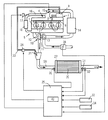
図1は、本発明の一実施形態としての排気ガス浄化装置を示す。排気ガス浄化装置は、内燃機関としての(以下、「エンジン」という)1に適用したものである。エンジン1は、4気筒であって、燃料供給系2、燃焼室3、吸気系4及び排気系5等を主要部として構成されている。燃料供給系2は、サプライポンプ9、コモンレール6、主噴射手段であり、空燃比変更手段としての機能するインジェクタ7を備えている。サプライポンプ9は、エンジン1によって駆動され、図示しない燃料タンクから汲み上げた燃料を高圧にし、機関燃料通路8を介してコモンレール6に供給する。コモンレール6は、サプライポンプ9から供給された高圧燃料を所定圧力に保持(蓄圧)する蓄圧室としての機能を有し、この蓄圧した燃料を各気筒の燃焼室3に臨むように配設されたインジェクタ7にそれぞれ分配する。
FIG. 1 shows an exhaust gas purifying apparatus as one embodiment of the present invention. The exhaust gas purifying device is applied to an internal combustion engine (hereinafter referred to as “engine”) 1. The
各インジェクタ7は、その内部に図示しない電磁ソレノイドを備えた周知の電磁弁である。各インジェクタ7は、前エンジン1の吸気行程及び圧縮行程の何れかにおいて機関運転状態に基づき燃料を直接筒内に供給するものであり、駆動力を得るための基本噴射量が図示しないマップによって定められている。
Each injector 7 is a known solenoid valve having an electromagnetic solenoid (not shown) therein. Each injector 7 supplies fuel directly into the cylinder based on the engine operating state in either the intake stroke or the compression stroke of the
吸気系4は、各燃焼室3内に供給される吸入空気の通路(吸気通路)を形成し、排気系5は、各燃焼室3から排出される排気ガスの通路(排気通路)を形成する。エンジン1には、周知の過給機であるターボチャージャ10が設けられている。ターボチャージャ10は、シャフト11を介して連結された回転体12,13を備えている。一方の回転体となるタービンホイール12は排気系5内の排気に晒され、他方の回転体となるコンプレッサホイール13は、吸気系4内の吸気に晒される。このような構成を有するターボチャージャ10は、タービンホイール12が受ける排気流(排気圧)を利用してコンプレッサホイール13を回転させ、吸気圧を高めるといった周知と過給を行う。コンプレッサホイール13よりも吸気上流側には、吸気系4内に導入される空気(吸入空気)の流量(吸気量)に応じた検出信号を出力するエアフロセンサ28が設けられている。
The
ターボチャージャ10よりも下流側の吸気系4に設けられたインタークーラ14は、過給によって昇温した吸入空気を強制冷却する。インタークーラ14よりもさらに下流に設けられ空燃比変更手段としての機能するスロットル弁15は、その開度を無段階に調節することのできる電子制御式の開閉弁であり、所定の条件下において吸入空気の流路面積を変更し、同吸入空気の供給量(流量)を調整する機能を有する。
An
エンジン1には、燃焼室3の上流(吸気系4)及び下流(排気系5)をバイパスする排気還流通路となるEGR通路16が形成されている。EGR通路16は、排気の一部を適宜吸気系4に戻す機能を有する。EGR通路16には、電子制御によって無段階に開閉され、同通路を流れる排気(EGRガス)の流量を自在に調整することができ、空燃比変更手段としても機能するEGR弁17と、EGR通路16を通過(還流)する排気を冷却するためのEGRクーラ18が設けられている。
The
タービンホイール12よりも排気ガス流出方向の下流側の排気通路50には、排気通路50を流れる排気ガス中に還元剤となる燃料を添加供給する還元剤供給手段であり、空燃比変更手段としても機能する還元剤噴射ノズル21と、ケーシング27内に収納され、排気ガスを浄化するための吸蔵還元型NOx触媒(以下「NOx触媒」と記す)20が配設されている。
The
還元剤噴射ノズル21は、添加燃料通路23を介してサプライポンプ9と接続されていて、燃料タンクから汲み上げられた燃料の一部が供給されるようになっている。添加燃料通路23には、サプライポンプ9から還元剤噴射ノズル21への燃料の流量と添加燃料通路23の開閉を行う電磁調量弁24が配設されている。電磁調整弁24は、その開閉タイミングが制御手段25によって制御され、NOx触媒20よりも上流側で還元剤となる燃料を排気通路50の排気ガス中に添加供給する。
The reducing
NOx触媒20よりも上流側の排気通路50には、空燃比(A/F)センサ30が配設されている。空燃比(A/F)センサ30は、ケーシング27上流において排気ガス中の酸素濃度に応じて連続的に変化する検出信号を出力する。NOx触媒20よりも下流側の排気通路50には、NOx触媒20の温度を検出する温度検出手段としての排気温度センサ32と、NOxセンサ31が配設されている。NOxセンサ31は、NOx触媒20の下流において排気ガス中のNOx濃度に応じて連続的に変化する検出信号を出力する。アクセルポジションセンサ33はエンジン1の図示しないアクセルペダルに取り付けられ、同ペダルの踏み込み量に応じた検出信号を出力する。クランク角センサ34は、エンジン1の出力軸(クランクシャフト)が一定角度回転する毎に検出信号(パルス)を出力する。これら各センサ30〜34は、制御装置25の入力側と電気的に接続されている。
An air-fuel ratio (A / F)
制御手段25は、CPU、ROM、RAM及びバックアップRAM、タイマカウンタ等を備えた周知のコンピュータで構成されている。制御手段25は、各種センサの検出信号を図示しない外部入力回路から入力し、これら信号に基づきインジェクタ7の開閉弁動作に関する制御や、EGR弁17の開度調整、或いはスロットル弁15の開度調整等、エンジン1の運転状態に関する各種制御を実施する。
The control means 25 is composed of a known computer having a CPU, ROM, RAM, backup RAM, timer counter, and the like. The control means 25 inputs detection signals of various sensors from an external input circuit (not shown), and controls the opening / closing valve operation of the injector 7, the opening adjustment of the EGR valve 17, or the opening adjustment of the
NOx触媒20は、ケーシング27に収納されて排気通路50上に装着されている。NOx触媒20は、ハニカム形状の構造体である担持体と、この担体体の表面にNOx吸蔵剤として機能する例えばカリウム(K)、ナトリウム(Na)、リチウム(Li)、セシウムCsのようなアルカリ金属、バリウムBa、カルシウムCaのようなアルカリ土類、ランタン(La)、或いはイットリウム(Y)のような希土類と、酸化触媒(貴金属触媒)として機能する例えば白金Ptのような貴金属とが担持されることによって構成されている。
The
NOx吸蔵剤は、排気ガスがリーンな状態ではNOxを吸蔵し、排気ガスがリッチな状態ではNOxを放出する特性を有する。排気ガス中にNOxが放出されたとき、排気ガス中にHCやCO等が存在していれば、貴金属触媒がこれらHCやCOの酸化反応を促すことで、NOxを酸化成分、HCやCOを還元成分とする酸化還元反応が両者間で起こる。すなわち、HCやCOはCO2やH2Oに酸化され、NOxはN2に還元される。 The NOx storage agent has a characteristic of storing NOx when the exhaust gas is lean and releasing NOx when the exhaust gas is rich. When NOx is released into the exhaust gas, if HC, CO, or the like is present in the exhaust gas, the noble metal catalyst promotes the oxidation reaction of these HC and CO, so that NOx becomes an oxidizing component and HC and CO A redox reaction as a reducing component occurs between the two. That is, HC and CO are oxidized to CO 2 and H 2 O, and NOx is reduced to N 2 .
NOx吸蔵剤は、排気ガスがリーン状態にあるときでも所定の限界量のNOxを吸蔵すると、それ以上NOxを吸蔵しなくなるので、該吸蔵させたNOxを上述の如く還元雰囲気中においてN2等に還元除去してやる必要がある。そこで、この排気ガス浄化装置では、例えば予め設定された所定周期で、所定時間に亘りEGRや吸気絞りによる吸入空気量の減少、エンジン噴射量の増大及び排気管への燃料噴射によるリッチ空燃比運転を行う、所謂リッチスパイクを実行し、これにより吸蔵型NOx触媒20内にCO過剰状態、即ち還元雰囲気を強制的に生起させ、吸蔵したNOxを放出し還元除去(NOxパージ)するようにしている。実際には、ECU25内のタイマカウンタによって上記所定周期が計時され、ECU25によりEGR弁17、スロットル弁15、インジェクタ7、還元剤噴射ノズル21が制御される。なお、所定周期は、通常のエンジン運転によって吸蔵型NOx触媒20に吸蔵されたNOxが飽和量に達したと推定される時間に基づき予め設定されているが、その他にも、例えば車両の走行距離に基づいて推定することもできる。すなわち、所定距離走行したらリッチ空燃比運転(リッチスパイク)を行うようにしてもよい。
The NOx occlusion agent does not occlude NOx any further when occluded a predetermined limit amount of NOx even when the exhaust gas is in a lean state. Therefore, the occluded NOx is reduced to N 2 or the like in the reducing atmosphere as described above. It needs to be reduced and removed. Therefore, in this exhaust gas purifying apparatus, for example, a rich air-fuel ratio operation by reducing the intake air amount by EGR or the intake throttle, increasing the engine injection amount, and fuel injection into the exhaust pipe over a predetermined time in a predetermined cycle set in advance. In this way, a so-called rich spike is executed, thereby forcibly generating a CO excess state, that is, a reducing atmosphere in the storage
ECU25は、各種センサの検出信号から把握されるエンジン1の運転状態に基づきインジェクタ7による燃料噴射制御を行う。ここでの燃料噴射制御とは、各インジェクタ7を通じた各燃焼室3内への燃料噴射の実施に関し、燃料の噴射量、噴射タイミング、噴射パターンといったパラメータを設定し、これら設定されたパラメータに基づいて各インジェクタ7の開閉弁操作を実行する一連の処理をいう。ECU25は、このような一連の処理を、エンジン1の運転中所定時間毎に繰り返し行う。燃料の噴射量や噴射タイミングはアクセルペダルヘの踏み込み量およびエンジン回転数(クランク角センサのパルス信号に基づいて演算することができるパラメータ)に基づき、予め設定された図示しないマップを参照して決定する。
The
ECU25は、燃料の噴射パターンの設定に関し、圧縮上死点近傍での燃料噴射を主噴射として各気筒について行うことで機関出力を得る他、主噴射に先立つ燃料噴射(以下、パイロット噴射という)や、主噴射に後続する燃料噴射(以下、ポスト噴射という)を、副噴射として適宜選択された時期、選択された気筒について行う。
The
ポスト噴射によって燃焼室3内に供給される燃料は、燃焼ガス中で軽質なHCに改質され、排気系5に排出される。すなわち、還元剤として機能する軽質なHCが、ポスト噴射を通じて排気系5に添加され、排気ガス中の還元成分濃度を高めることとなる。排気系5に添加された還元成分はNOx触媒20を介し、同NOx触媒から放出されるNOxや排気ガス中に含まれるその他の酸化成分と反応する。このとき発生する反応熱は、NOX触媒の床温(温度)を上昇させる。なお、リッチ空燃比運転(リッチスパイク)としては、所定周期毎にインジェクタ7による主噴射時の噴射量増大制御ではなく、ポスト噴射を実行してもよい。
The fuel supplied into the
ECU25は、各種センサの検出信号から把握されるエンジン1の運転状態に基づきEGR制御を実施する。EGR制御とは、EGR通路16に設けられたEGR弁17を駆動操作して、EGR通路16を通過するガスの流量、すなわち、排気系5から吸気系4に還流される排気ガスの流量調整を行う処理のことをいう。
The
目標となるEGR弁17の開弁量(以下、目標開弁量)は、基本的にはエンジン1の負荷や回転数等の運転状態に基づき、予め設定された図示しないマップを参照して決定される。ECU25は、この目標開弁量をエンジン1の運転中所定時間毎に更新し、逐次、EGR弁17の実際の開弁量が更新された目標開弁量に合致するよう同EGR弁17の駆動回路に指令信号を出力する。
The target valve opening amount of the EGR valve 17 (hereinafter referred to as the target valve opening amount) is basically determined based on the operation state such as the load and the rotational speed of the
還元剤噴射ノズル21を通じ、燃料(還元剤)を排気系5に直接添加することによっても、ポスト噴射と同様、排気ガス中の還元成分濃度を高め、結果としてNOx触媒20の床温を上昇させることができる。還元剤噴射ノズル21によって添加された燃料は、ポスト噴射によるものに比べ、排気ガス中においてより高分子の状態を保持しつつ不均一に分布する傾向がある。また、還元剤噴射ノズル21による燃料添加では、一度に添加することのできる燃料量や添加タイミングの自由度が、ポスト噴射による場合よりも大きい。
By directly adding the fuel (reducing agent) to the exhaust system 5 through the reducing
次にS被毒回復制御の概要について述べる。上記ポスト噴射および燃料添加制御は、共通して排気ガス中の還元成分を増量するように作用するため、何れかの制御を所定の間隔で繰り返し実施することにより、NOx触媒20に吸蔵されたNOxを放出および還元浄化し、NOx触媒20のNOx吸蔵能力を回復させることができる。
Next, the outline of the S poison recovery control will be described. The post injection and the fuel addition control commonly operate so as to increase the reducing component in the exhaust gas. Therefore, the NOx occluded in the
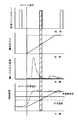
ECU25は、エンジン1の機関運転の継続に伴いNOx触媒20に徐々に吸蔵されるSOx等を除去するために、図2に示すように、NOx触媒20を目標温度(例えば600℃程度)以上にまで昇温させた上で、触媒前の空燃比を理論空燃比以下とするリッチ化制御(以下、S披毒回復制御)を実施する。S被毒回復制御を実施することにより、NOx触媒20に供給された多量の還元成分が、当該触媒に吸蔵したSOxを高温条件下で除去するようになる。ECU25は、S披毒回復制御の一環として、NOx触媒20を目標温度にまで昇温するために上記ポスト噴射あるいは排気燃料添加制御を実施する。本形態では、NOx触媒20に吸蔵されたNOxの放出および還元浄化に要する量よりも多量の燃料(還元成分)を、還元剤噴射ノズル21を通じてNOx触媒20の上流に供給する制御(以下、還元成分供給制御という)を実施する。
As shown in FIG. 2, the
S被毒回復制御では、図2に示すように、NOx触媒20の温度をS被毒回復に必要な温度となるSパージ目標温度(600℃)以上に保持するといった条件を成立させた上で、排気系内におけるNOX触媒上流へ多量の還元成分を供給することになる。ところが、排気系内に供給された多量の還元成分は、高温条件下においてNOx触媒20に吸蔵したSOx等を除去する機能を発揮する一方、NOx触媒20の温度をさらに上昇させる特性を有する。このため、通常の運転条件下において、多量の還元成分を排気系のNOx触媒上流に継続して供給した場合、NOx触媒20が過熱してしまう懸念と、熱解離により吸蔵されているNOxが放出されてしまうことが懸念される。
In the S poison recovery control, as shown in FIG. 2, the condition that the temperature of the
このため、ECU25は、被毒回復時期判定手段42を有し、被毒回復時期判定手段42により実行時期であると判定されると、還元剤噴射ノズル21から添加される還元剤の添加量を除々に増加させるとともに、排気温度センサ32からの検出温度がNOx触媒20の熱解離温度よりも低い所定温度(図2)の場合に、EGR弁17、スロットル弁15、インジェクタ7及び還元剤噴射ノズル21を制御して空燃比をリッチ状態するリッチスパイクを実行する。すなわち、リッチスパイクの所定周期が、熱解離温度よりも低い温度の場合に到達した場合には、リッチスパイクを実行し、熱解離温度よりも低い温度と所定周期とがずれている場合には、所定周期を無視して熱解離温度よりも低い温度の時に強制的にリッチスパイクを実行する。
For this reason, the
被毒回復時期判定手段42は、NOx触媒20に対するS被毒が進行しているか否かを判断するものである。本形態において、被毒回復時期判定手段42は、NOxセンサ31の検出信号の履歴から回復時期を判断してNOx触媒20によるNOxの浄化機能が低下していると認識される場合、S被毒回復制御の実行時期となるSパージ信号を出力する。
還元剤噴射ノズル21から添加される還元剤の添加量は、図2に示すように、Sパージ信号が出力されてからの経過時間が進む程に増大するように予め試験によって求められてマップ化されている。
The poisoning recovery time determination means 42 determines whether or not S poisoning on the
As shown in FIG. 2, the amount of reducing agent added from the reducing
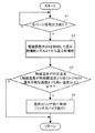
このような構成の排気ガス浄化装置のS被毒回復制御について、図3に示すフローチャートに沿って説明する。ステップS1ではSパージ信号の出力の有無が判断され、この信号が出力されている場合にはステップS2に進み、電磁調整弁24がECU25によって制御され、還元剤となる燃料の噴射量(添加量)が還元剤噴射ノズル21から排気ガス中に通常よりも少なく噴射されることで添加される。排気系5においては、添加された燃料によりNOx触媒20の温度が図2に示すように緩やかに昇温する。ECU25は、温度センサ32からの信号を取り込み、ステップS3において、検出した触媒温度がNOx還元可能な温度以上で、かつ所定温度(熱解離温度より所定量低い温度)よりも低い場合にはステップS4に進んでリッチスパイクを実行する。
The S poisoning recovery control of the exhaust gas purifying apparatus having such a configuration will be described with reference to the flowchart shown in FIG. In step S1, it is determined whether or not an S purge signal is output. If this signal is output, the process proceeds to step S2, in which the
このように、被毒回復時期判定手段42から実行時期であるSパージ信号が出力されると、電磁調整弁24を開閉制御して還元剤噴射ノズル21から添加される還元剤の添加量を除々に増加させるので、触媒昇温が緩やかになる。また、還元剤の添加量の増加中において、排気温度センサ32からの検出温度がNOx触媒20の熱解離温度よりも低い所定温度の場合には空燃比をリッチ状態とするので、NOx触媒20に吸蔵されているNOxを、NOx触媒20が熱解離温度に到達する前に低減することができる。このため、排気ガスによりNOx触媒20が昇温され熱解離温度に到達したときに発生するNOxスリップ量を低減することができる。また、触媒の昇温速度が緩やかになることで、NOx触媒20の過度な温度上昇(過昇温)を抑制することができ、熱劣化を低減でき、耐久性が向上する。
Thus, when the S purge signal, which is the execution time, is output from the poisoning recovery time determination means 42, the
図2においては、2点鎖線は、NOx触媒20をSパージ目標温度まで一気に昇温させるだけの添加剤を還元剤噴射ノズル21から噴射した場合のNOxスリップ量とNOx触媒20の温度上昇を示し、実線は、本形態のように還元剤噴射ノズル21から添加剤を徐々に増やし、熱解離温度到達前にリッチスパイクを一度実施した時のNOxスリップ量と触媒温度上昇の特性を示す。図2からも明らかなように、熱解離温度よりも低い所定温度時にリッチスパイクを実施すると、NOxスリップ量が激減するのが読み取れる。
In FIG. 2, the two-dot chain line indicates the NOx slip amount and the temperature rise of the
1 内燃機関
7,15,17 空燃比変更手段
20 吸蔵還元型NOX触媒
21 還元剤供給手段
25 制御手段
32 温度検出手段
42 被毒回復時期判定手段
50 排気通路
1 an
Claims (1)
前記空燃比を変更する空燃比変更手段と、
前記吸蔵還元型NOx触媒に還元剤を添加する還元剤供給手段と、
前記吸蔵還元型NOx触媒の温度を検出する温度検出手段と、
前記吸蔵還元型NOx触媒からSOXを放出させるSOX被毒回復処理を実行する時期を判定する被毒回復時期判定手段と、
前記被毒回復時期判定手段により実行時期であると判定されると、前記還元剤供給手段から添加される還元剤の添加量を除々に増加させるとともに、前記温度検出手段からの検出温度が前記吸蔵還元型NOx触媒の熱解離温度よりも低く、かつNOx還元可能な温度よりも高い場合に、前記空燃比変更手段を制御して前記空燃比をリッチ状態とする制御手段とを有することを特徴とする排気ガス浄化装置。
An occlusion reduction system that is provided in the exhaust passage of a lean burnable internal combustion engine and stores NOx when the air-fuel ratio of the inflowing exhaust gas is lean, and releases the stored NOx when the air-fuel ratio of the inflowing exhaust gas is rich Type NOx catalyst,
Air-fuel ratio changing means for changing the air-fuel ratio;
Reducing agent supply means for adding a reducing agent to the NOx storage reduction catalyst;
Temperature detecting means for detecting the temperature of the NOx storage reduction catalyst;
Poisoning recovery time determination means for determining a time to execute SO X poisoning recovery processing for releasing SO X from the NOx storage reduction catalyst;
When the poisoning recovery time determining means determines that it is the execution time, the amount of reducing agent added from the reducing agent supply means is gradually increased and the detected temperature from the temperature detecting means is stored in the occlusion. Control means for controlling the air-fuel ratio changing means to bring the air-fuel ratio into a rich state when the temperature is lower than the thermal dissociation temperature of the reduced NOx catalyst and higher than the temperature at which NOx reduction is possible. Exhaust gas purifier.
Priority Applications (5)
| Application Number | Priority Date | Filing Date | Title |
|---|---|---|---|
| JP2004105849A JP2005291058A (en) | 2004-03-31 | 2004-03-31 | Exhaust emission control device |
| DE102005014872A DE102005014872A1 (en) | 2004-03-31 | 2005-03-30 | exhaust gas purification device |
| US11/094,788 US20050223698A1 (en) | 2004-03-31 | 2005-03-30 | Exhaust gas cleaning device |
| KR1020050027387A KR100679540B1 (en) | 2004-03-31 | 2005-03-31 | Exhaust gas purifier |
| CNA200510059868XA CN1676893A (en) | 2004-03-31 | 2005-03-31 | Exhaust gas cleaning device |
Applications Claiming Priority (1)
| Application Number | Priority Date | Filing Date | Title |
|---|---|---|---|
| JP2004105849A JP2005291058A (en) | 2004-03-31 | 2004-03-31 | Exhaust emission control device |
Publications (1)
| Publication Number | Publication Date |
|---|---|
| JP2005291058A true JP2005291058A (en) | 2005-10-20 |
Family
ID=35324282
Family Applications (1)
| Application Number | Title | Priority Date | Filing Date |
|---|---|---|---|
| JP2004105849A Pending JP2005291058A (en) | 2004-03-31 | 2004-03-31 | Exhaust emission control device |
Country Status (1)
| Country | Link |
|---|---|
| JP (1) | JP2005291058A (en) |
Cited By (4)
| Publication number | Priority date | Publication date | Assignee | Title |
|---|---|---|---|---|
| JP2014118966A (en) * | 2012-12-18 | 2014-06-30 | Hyundai Motor Company Co Ltd | Lnt control method for vehicle |
| CN104047691A (en) * | 2013-03-15 | 2014-09-17 | 通用汽车环球科技运作有限责任公司 | Rejuvenation control of palladium-only diesel oxidation catalyst |
| JP2018119518A (en) * | 2017-01-27 | 2018-08-02 | マツダ株式会社 | Exhaust emission control device for engine |
| JP2018119519A (en) * | 2017-01-27 | 2018-08-02 | マツダ株式会社 | Exhaust emission control device for engine |
-
2004
- 2004-03-31 JP JP2004105849A patent/JP2005291058A/en active Pending
Cited By (5)
| Publication number | Priority date | Publication date | Assignee | Title |
|---|---|---|---|---|
| JP2014118966A (en) * | 2012-12-18 | 2014-06-30 | Hyundai Motor Company Co Ltd | Lnt control method for vehicle |
| CN104047691A (en) * | 2013-03-15 | 2014-09-17 | 通用汽车环球科技运作有限责任公司 | Rejuvenation control of palladium-only diesel oxidation catalyst |
| CN104047691B (en) * | 2013-03-15 | 2016-09-14 | 通用汽车环球科技运作有限责任公司 | The recovery of single palladium diesel oxidation catalyst controls |
| JP2018119518A (en) * | 2017-01-27 | 2018-08-02 | マツダ株式会社 | Exhaust emission control device for engine |
| JP2018119519A (en) * | 2017-01-27 | 2018-08-02 | マツダ株式会社 | Exhaust emission control device for engine |
Similar Documents
| Publication | Publication Date | Title |
|---|---|---|
| KR100679540B1 (en) | Exhaust gas purifier | |
| US7454900B2 (en) | Catalyst recovery method | |
| CN101326349B (en) | Exhaust purification system for internal combustion engines | |
| JP2003106136A (en) | Exhaust purification device for internal combustion engine | |
| JP3815289B2 (en) | Exhaust gas purification device for internal combustion engine | |
| EP1867854B1 (en) | Exhaust purifier for internal combustion engine | |
| JP3800080B2 (en) | Exhaust gas purification device for internal combustion engine | |
| JP3826824B2 (en) | Exhaust gas purification apparatus for internal combustion engine and catalyst function management method | |
| US10933374B2 (en) | Exhaust emission control device, method and computer program product for an engine | |
| WO2014167652A1 (en) | Exhaust purification device of internal combustion engine | |
| US10801432B2 (en) | Control device for engine | |
| JP4385617B2 (en) | Exhaust gas purification system for internal combustion engine | |
| JP2005291057A (en) | Exhaust emission control device | |
| JP2005291058A (en) | Exhaust emission control device | |
| JP4357241B2 (en) | Exhaust purification equipment | |
| JP4284919B2 (en) | Exhaust gas purification device for internal combustion engine and control method thereof | |
| JP2003286878A (en) | Exhaust purification device and exhaust purification method for internal combustion engine | |
| JP4106913B2 (en) | Exhaust gas purification device for internal combustion engine | |
| JP4193553B2 (en) | Exhaust gas purification device for internal combustion engine | |
| JP2003269230A (en) | Internal combustion engine | |
| JP2010127182A (en) | Exhaust emission control device for internal combustion engine | |
| JP2005291059A (en) | Exhaust emission control device | |
| JP5024221B2 (en) | Engine control device | |
| JP2004346844A (en) | Exhaust gas purification system | |
| JP2004232555A (en) | Exhaust gas purification system for internal combustion engine |
Legal Events
| Date | Code | Title | Description |
|---|---|---|---|
| A621 | Written request for application examination |
Free format text: JAPANESE INTERMEDIATE CODE: A621 Effective date: 20070118 |
|
| A977 | Report on retrieval |
Free format text: JAPANESE INTERMEDIATE CODE: A971007 Effective date: 20090827 |
|
| A131 | Notification of reasons for refusal |
Free format text: JAPANESE INTERMEDIATE CODE: A131 Effective date: 20090929 |
|
| A02 | Decision of refusal |
Free format text: JAPANESE INTERMEDIATE CODE: A02 Effective date: 20100216 |