EP1475178A1 - Brazed sintered compact - Google Patents
Brazed sintered compact Download PDFInfo
- Publication number
- EP1475178A1 EP1475178A1 EP03010305A EP03010305A EP1475178A1 EP 1475178 A1 EP1475178 A1 EP 1475178A1 EP 03010305 A EP03010305 A EP 03010305A EP 03010305 A EP03010305 A EP 03010305A EP 1475178 A1 EP1475178 A1 EP 1475178A1
- Authority
- EP
- European Patent Office
- Prior art keywords
- components
- component
- joining
- brazing material
- protrusion
- Prior art date
- Legal status (The legal status is an assumption and is not a legal conclusion. Google has not performed a legal analysis and makes no representation as to the accuracy of the status listed.)
- Withdrawn
Links
- 238000005219 brazing Methods 0.000 claims abstract description 70
- 238000005304 joining Methods 0.000 claims abstract description 68
- 239000000463 material Substances 0.000 claims abstract description 64
- 238000003860 storage Methods 0.000 claims abstract description 41
- 239000012466 permeate Substances 0.000 claims abstract description 9
- 230000002093 peripheral effect Effects 0.000 claims description 19
- 239000008188 pellet Substances 0.000 claims description 5
- 239000000843 powder Substances 0.000 claims description 4
- 239000002184 metal Substances 0.000 claims description 3
- 229910052751 metal Inorganic materials 0.000 claims description 3
- 238000005245 sintering Methods 0.000 description 5
- 238000000034 method Methods 0.000 description 3
- 239000000969 carrier Substances 0.000 description 2
- 238000010586 diagram Methods 0.000 description 2
- 230000002708 enhancing effect Effects 0.000 description 2
- 238000004519 manufacturing process Methods 0.000 description 2
- 229910001018 Cast iron Inorganic materials 0.000 description 1
- RYGMFSIKBFXOCR-UHFFFAOYSA-N Copper Chemical compound [Cu] RYGMFSIKBFXOCR-UHFFFAOYSA-N 0.000 description 1
- 229910052802 copper Inorganic materials 0.000 description 1
- 239000010949 copper Substances 0.000 description 1
- 230000000694 effects Effects 0.000 description 1
- 238000003754 machining Methods 0.000 description 1
- 238000012986 modification Methods 0.000 description 1
- 230000004048 modification Effects 0.000 description 1
- 230000035515 penetration Effects 0.000 description 1
- 238000003825 pressing Methods 0.000 description 1
- 239000000047 product Substances 0.000 description 1
Images

Classifications
-
- B—PERFORMING OPERATIONS; TRANSPORTING
- B23—MACHINE TOOLS; METAL-WORKING NOT OTHERWISE PROVIDED FOR
- B23K—SOLDERING OR UNSOLDERING; WELDING; CLADDING OR PLATING BY SOLDERING OR WELDING; CUTTING BY APPLYING HEAT LOCALLY, e.g. FLAME CUTTING; WORKING BY LASER BEAM
- B23K1/00—Soldering, e.g. brazing, or unsoldering
- B23K1/19—Soldering, e.g. brazing, or unsoldering taking account of the properties of the materials to be soldered
-
- B—PERFORMING OPERATIONS; TRANSPORTING
- B23—MACHINE TOOLS; METAL-WORKING NOT OTHERWISE PROVIDED FOR
- B23K—SOLDERING OR UNSOLDERING; WELDING; CLADDING OR PLATING BY SOLDERING OR WELDING; CUTTING BY APPLYING HEAT LOCALLY, e.g. FLAME CUTTING; WORKING BY LASER BEAM
- B23K2101/00—Articles made by soldering, welding or cutting
- B23K2101/006—Vehicles
-
- B—PERFORMING OPERATIONS; TRANSPORTING
- B23—MACHINE TOOLS; METAL-WORKING NOT OTHERWISE PROVIDED FOR
- B23K—SOLDERING OR UNSOLDERING; WELDING; CLADDING OR PLATING BY SOLDERING OR WELDING; CUTTING BY APPLYING HEAT LOCALLY, e.g. FLAME CUTTING; WORKING BY LASER BEAM
- B23K2101/00—Articles made by soldering, welding or cutting
- B23K2101/04—Tubular or hollow articles
Definitions
- the present invention relates to a brazed sintered compact in which two components are brazed to each other, using a brazing material.
- a brazed sintered compact in which a first component and a second component are formed by sintering, and then the two components are brazed to each other.
- Such method has been utilized for manufacturing a product of complex shape, such as planetary carriers for use with an automatic shift for automobiles.
- Such planetary carriers have been manufactured in the past by subjecting an entire perimeter of cast iron material or a copper plate material to machine processing, resulting to increased man-hours and costs. Therefore, they are now manufactured through the above-mentioned method, i.e., by forming first and second components by sintering green compact and then brazing them to each other.
- This prior art discloses brazed sintered compact consisting at least of a first component and a second component to be brazed to the first component, in which one of the first and second components has a joining surface formed with a protrusion, while the other thereof has a joining surface formed with a recess, said recess being fitted to said protrusion, having such a depth as allow for a desirable joining clearance with the protrusion being fitted into the recess; and that one of the joining surfaces is formed in a perimeter thereof with a storage groove for storing surplus brazing material, thereby preventing the brazing material from flowing out to the external of the components owing to such groove.
- the components slightly overhang the groove so that the surplus brazing material is unlikely to be easily discharged, and that the joining clearance could not be optimized due to the backflow of the brazing material which flowed out to the external and the resultant re-permeation thereby.
- a brazed sintered compact in accordance with a first aspect of the present invention, which is composed of at least a first component and a second component, each component having a joining surface and joined to each other by brazing, comprising:
- both components can be simply positioned relative to each other by fitting the protrusion into the recess. At the same time, it is possible to easily obtain a joining clearance, corresponding to a dimensional difference between the first and the second components.
- both components are sintered with the joining clearance being filled with the brazing material after the joining clearance is set at a predetermined dimension for permeation of the brazing material, it is possible to allow as much brazing material as properly needed to permeate between the joining surfaces of the first and second components, thus enabling a desirable brazing strength to be obtained reliably, thereby enhancing the reliability of the brazing strength.
- a second aspect of the invention is a brazed sintered compact composed of similar components of the first aspect, including at least one storage groove formed on a peripheral edge of the joining surface of one of the first and second components, said storage groove being provided for storing a surplus amount of a brazing material, arranged such that an inside surface of the storage groove is aligned with an opposite portion of the other of the first and second components.
- a third aspect of the invention is a brazed sintered compact according to the second aspect, featured by that said clearance has such a dimension as properly needed to allow the brazing material to permeate between the joining surfaces of said first and second components.
- a fourth aspect of the invention is a brazed sintered compact according to the third aspect, in which said first component and second component are annular plate materials each of which is formed from metal powder individually, and then they are combined with each other while a brazing material is filled in between the joining surfaces of the components, so that both components are sintered at a predetermined temperature in a furnace, at the same time that the brazing material is fused so as to braze one of the joining surfaces of the components to the other thereof.
- a fifth aspect of the invention is a brazed sintered compact according to the forth aspect, in which said storage groove is fully opened upward.
- a sixth aspect of the invention is a brazed sintered compact according to the fifth aspect, in which one of said first and second components is formed with a protrusion or a recess, while the other thereof is formed with a leg opposite thereto, said leg including a recess or a protrusion on a distal joining surface thereof, and wherein the inner side surface of said storage groove is aligned with a right or a left end of said leg.
- the surplus brazing material on the right or left side of said leg can be stored in said storage groove.
- a seventh aspect of the invention is a brazed sintered compact according to the sixth aspect, in which a hole for inserting a brazing material pellet is formed between the right and the left storage grooves.
- the brazing material pellet can be inserted from the hole.
- An eighth aspect of the invention is a brazed sintered compact according to the fifth aspect, in which one of said first and second components is formed with a protrusion or a recess, while the other thereof is formed with a leg opposite thereto, said leg including a recess or a protrusion on a distal joining surface thereof, and wherein the inner side surface of said storage groove is aligned with a peripheral edge of the peripheral outer surface of said leg.
- the surplus brazing material on the peripheral outer surface side of said leg can be stored in said storage groove.
- a ninth aspect of the invention is a brazed sintered compact according to the fifth aspect, in which said first component and second component in the form of said annular plate member is a planetary carrier composed of a pair of side plates which oppose to each other with a planetary pinion therebetween.
- the brazed sintered compact of the invention is a planetary carrier of such a complex shape, it can be easily manufactured.
- a brazed sintered compact of the invention is made up of a first component 1 and a second component 10.
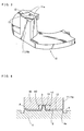
- the first component 1 is provided in the form of an annular plate member as shown in Figs. 1 and 2, while the second component 10 as another annular plate member with several legs 11 (three legs provided at equal angular intervals in the embodiment) protruded therefrom, as shown in Fig.3.
- reference symbol H denotes a hole provided in the first component 1 for inserting a brazing material pellet thereinto.
- the first component 1 and the second component 10 take the shape of an annular plate member, respectively, illustrating an example of a planetary carrier composed of a pair of side plates which oppose to each other with a planetary pinion (not shown) therebetween.
- first component 1 and second component 10 are each formed by applying pressure to a powder material, and then they are combined with each other while a brazing material is filled in between the joining surfaces of the components. Thereafter, the first component 1 and the second component 10 with the brazing material being filled therebetween are brought into a sintering furnace, so that both components are sintered at a predetermined temperature, at the same time that the brazing material is fused so as to braze one of the joining surfaces of the components to the other thereof.
- a joining surface 2 of the first component 1 is formed with a protrusion 3 which protrudes toward the second component 10 in order to position the first component 1 relative to the second component 10, as illustrated in Fig.2
- the protrusion 3 is provided adjacent to an inner edge of the joining surface of the first component 1, said protrusion 3 being tapered from a proximal portion toward a distal end thereof.
- a joining surface 12 of the leg 11 of the second component 10 is formed with a recess 13 for fitting the protrusion 3 thereinto, said recess 13 being opposed to said protrusion 3.
- a depth h2 of the recess 13 is set at a slightly smaller dimension than a protruding length h1 of the protrusion 3, as shown in Fig.4.
- the joining clearance A should have a dimension for allowing the brazing material to permeate the joining surfaces between the first component 1 and the second component 10. Accordingly, the difference between the protruding length h1 of the protrusion 3 and the depth h2 of the recess 13 is set at a value needed for a sufficient amount of the brazing material to permeate.
- the joining surface 2 of the first component 1 is formed with storage grooves 4, 4' for storing a surplus amount of the brazing material, as shown in Figs. 2 and 4.
- These storage grooves 4,4' are provided in certain positions on the joining surface 2 of the first component 1, each having a suitable depth and width, corresponding to the peripheral edges of right and left ends 11a of the leg 11 of the second component 10 or the peripheral edge of the outer peripheral surface 11b of the leg 11, whereby the surplus brazing material is allowed to be colleted therein when the brazing material is fused in the joining clearance A between the first component 1 and the second component 10.
- an inner side surface 4a of the storage groove 4 i.e. , one of the side surfaces of the storage groove 4 which is on the leg 11 side, is aligned with the left or right edge 11a of the leg 11, disposed opposite to the groove 4.
- Such arrangement is effected by fitting the protrusion 3 into the recess 13.
- an inner side surface 4'a of the storage groove 4' i.e. , one of the side surfaces of the storage groove 4' which is on the leg 11 side, is aligned with the peripheral edge of the outer peripheral surface 11b of the leg 11, disposed opposite to the groove 4'.
- Between the paired right and left grooves 4 is formed the aforesaid hole H for inserting a brazing material pellet.
- the protrusion 3 is formed on the joining surface 2 of the first component 1, while the recess 13 of which the dimension is smaller than the height of the protrusion 3 is formed on the joining surface 12 of the leg 11 of the second component 10, so that if only the protrusion 3 of the first component 1 is fitted into the recess 13 of the second component 10, not only can both components 1 and 10 be properly positioned relative to each other, but also can the joining clearance A be easily obtained between the joining surface 2 of the first component 1 and the joining surface 12 of the second component, corresponding to the dimensional difference therebetween.
- both components are sintered with the clearance A being filled with the brazing material after the joining clearance A is set at a predetermined dimension for permeation of the brazing material, it is possible to allow as much brazing material as properly needed to permeate between the joining surfaces 2 and 12 of the first and second components 1 and 10, thus enabling a desirable brazing strength to be obtained reliably, thereby enhancing the reliability of the brazing strength. It is to be noted that finish machining is performed after being joined thus way.
- the storage grooves 4,4' are provided on the joining surface 2 of the first component 1 so that the surplus amount of the brazing material may be stored therein, whereby not only can the surplus brazing material be prevented from coming out of the components, which eliminates the risk of impairing the appearance, but also can the trouble of removing the surplus brazing material be saved. Still also, as the storage grooves 4,4' are provided in the positions corresponding to the peripheral edge of the right and left ends 11a of the leg 11 of the second component, and the peripheral edge of the peripheral outer surface 11b of the leg 11, respectively, a relatively large amount of the surplus brazing material can be accommodated therein.
- the inside surfaces 4a, 4'a of the storage grooves 4, 4' are each aligned with the side surface of the left or right edge 11a of the leg 11 and the peripheral edge of the peripheral outer surface 11b of the leg 11, disposed opposite to the groove 4.4', while these storage grooves 4, 4' are fully opened upward, whereby the length of the clearance A overhanging the storage grooves 4,4' is reduced to minimum, thus facilitating the prompt discharge of the surplus brazing material to the outside.
- the present invention should not be limited to the above-mentioned embodiment but various modifications are possible within the scope of the invention.
- the protrusion 3 is provided on the first component 1 and the recess 13 on the leg 11 of the second component 10 in the foregoing embodiment, the arrangement thereof is not limited thereto.
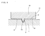
- the protrusion 3 may be provided on the latter while the recess 13 on the former, as shown in Fig.5, and any other arrangement may be employed as long as the same action and effect of the invention is attained.
- the first component 1 and the second component 10 are subjected to sintering and brazing at the same time in the foregoing embodiment, they may be separately sintered and then subjected to brazing process.
Landscapes
- Engineering & Computer Science (AREA)
- Chemical & Material Sciences (AREA)
- Materials Engineering (AREA)
- Mechanical Engineering (AREA)
- Powder Metallurgy (AREA)
Abstract
Description
- The present invention relates to a brazed sintered compact in which two components are brazed to each other, using a brazing material.
- For conventional art of this kind, it is widely recognized to manufacture a brazed sintered compact in which a first component and a second component are formed by sintering, and then the two components are brazed to each other. Such method has been utilized for manufacturing a product of complex shape, such as planetary carriers for use with an automatic shift for automobiles. Such planetary carriers have been manufactured in the past by subjecting an entire perimeter of cast iron material or a copper plate material to machine processing, resulting to increased man-hours and costs. Therefore, they are now manufactured through the above-mentioned method, i.e., by forming first and second components by sintering green compact and then brazing them to each other.
- According to the conventional art, when joining the first and second components to each other.by brazing, they are combined together by precise positioning therebetween. In that case, a joining clearance for allowing a brazing material to permeate between the two components becomes a problem.
- In other words, if a joining clearance is too large, the penetration amount of the brazing material into the respective components will be too much, so that the components will be expanded and thus distorted, resulting to a likelihood of the noticeable drop of the components' strength. On the other hand, if a joining clearance is too small, there is a risk that the joint strength between the two components drops. Accordingly, it has been a problem how such joining clearance for allowing a brazing material to permeate could be optimized.
- Also, the conventional art had another problem that as a brazing material would be very likely to flow out to the external when the brazing material was placed between the components and heated, such surplus brazing material had to be removed. A solution for solving such problem is proposed by the same applicant in Japanese Patent Application No. 2000-270581 (Publication No.2002-79372). This prior art discloses brazed sintered compact consisting at least of a first component and a second component to be brazed to the first component, in which one of the first and second components has a joining surface formed with a protrusion, while the other thereof has a joining surface formed with a recess, said recess being fitted to said protrusion, having such a depth as allow for a desirable joining clearance with the protrusion being fitted into the recess; and that one of the joining surfaces is formed in a perimeter thereof with a storage groove for storing surplus brazing material, thereby preventing the brazing material from flowing out to the external of the components owing to such groove.
- According to the prior art disclosed in the above earlier application, however, the components slightly overhang the groove so that the surplus brazing material is unlikely to be easily discharged, and that the joining clearance could not be optimized due to the backflow of the brazing material which flowed out to the external and the resultant re-permeation thereby.
- Accordingly, it is an object of the present invention to provide a brazed sintered compact in which components to be joined are able to be easily positioned relative to each other, at the same time that a good and precise joining clearance can be obtained.
- To attaint the object, there is proposed a brazed sintered compact in accordance with a first aspect of the present invention, which is composed of at least a first component and a second component, each component having a joining surface and joined to each other by brazing, comprising:
- a protrusion formed on the joining surface of one of the first and second components;
- a recess formed on the joining surface of the other of the first and second components, said recess being fitted to said protrusion, having such a depth as allows for a desirable joining clearance between the first and the second components when the former is fitted to the latter;
- at least one storage groove formed on the joining surface of one of the first and second components, said storage groove being provided for storing a surplus amount of a brazing material, and disposed opposite to a side portion of the other of the first and second components.
-
- As the joining surface of one of the components is formed with the protrusion while that of the other thereof is formed with a recess whose dimension is smaller than the height of the protrusion, both components can be simply positioned relative to each other by fitting the protrusion into the recess. At the same time, it is possible to easily obtain a joining clearance, corresponding to a dimensional difference between the first and the second components.
- Accordingly, if both components are sintered with the joining clearance being filled with the brazing material after the joining clearance is set at a predetermined dimension for permeation of the brazing material, it is possible to allow as much brazing material as properly needed to permeate between the joining surfaces of the first and second components, thus enabling a desirable brazing strength to be obtained reliably, thereby enhancing the reliability of the brazing strength.
- A second aspect of the invention is a brazed sintered compact composed of similar components of the first aspect, including at least one storage groove formed on a peripheral edge of the joining surface of one of the first and second components, said storage groove being provided for storing a surplus amount of a brazing material, arranged such that an inside surface of the storage groove is aligned with an opposite portion of the other of the first and second components.
- With the structure, as the inside surface of the storage groove is aligned with an opposite portion of the other of the first and second components, the backflow of the surplus brazing material stored in the storage groove due to the surface tension thereof is prevented, enabling the permeation of as much brazing material as properly needed into between the first and the second components.
- A third aspect of the invention is a brazed sintered compact according to the second aspect, featured by that said clearance has such a dimension as properly needed to allow the brazing material to permeate between the joining surfaces of said first and second components.
- Accordingly, it is possible to easily obtain a joining clearance, corresponding to a dimensional difference between the first and the second components, so that the permeation of the brazing material is insured.
- A fourth aspect of the invention is a brazed sintered compact according to the third aspect, in which said first component and second component are annular plate materials each of which is formed from metal powder individually, and then they are combined with each other while a brazing material is filled in between the joining surfaces of the components, so that both components are sintered at a predetermined temperature in a furnace, at the same time that the brazing material is fused so as to braze one of the joining surfaces of the components to the other thereof.
- With the structure, sintering of the first and second components composed of metal powder, can be carried out simultaneously with the brazing of them.
- A fifth aspect of the invention is a brazed sintered compact according to the forth aspect, in which said storage groove is fully opened upward.
- Accordingly, as the surface tension of the surplus brazing material becomes unlikely to be developed in the storage groove, the backflow of the surplus brazing material is prevented.
- A sixth aspect of the invention is a brazed sintered compact according to the fifth aspect, in which one of said first and second components is formed with a protrusion or a recess, while the other thereof is formed with a leg opposite thereto, said leg including a recess or a protrusion on a distal joining surface thereof, and
wherein the inner side surface of said storage groove is aligned with a right or a left end of said leg. - With the structure, the surplus brazing material on the right or left side of said leg can be stored in said storage groove.
- A seventh aspect of the invention is a brazed sintered compact according to the sixth aspect, in which a hole for inserting a brazing material pellet is formed between the right and the left storage grooves.
- Thus, the brazing material pellet can be inserted from the hole.
- An eighth aspect of the invention is a brazed sintered compact according to the fifth aspect, in which one of said first and second components is formed with a protrusion or a recess, while the other thereof is formed with a leg opposite thereto, said leg including a recess or a protrusion on a distal joining surface thereof, and wherein the inner side surface of said storage groove is aligned with a peripheral edge of the peripheral outer surface of said leg.
- Thus, the surplus brazing material on the peripheral outer surface side of said leg can be stored in said storage groove.
- A ninth aspect of the invention is a brazed sintered compact according to the fifth aspect, in which said first component and second component in the form of said annular plate member is a planetary carrier composed of a pair of side plates which oppose to each other with a planetary pinion therebetween.
- With the structure, even if the brazed sintered compact of the invention is a planetary carrier of such a complex shape, it can be easily manufactured.
- For more complete understanding of the present invention, reference is now made to the following description taken in conjunction with the accompanying drawings, in which:
- Fig.1 is a perspective view showing a brazed sintered compact according to an embodiment of the present invention.
- Fig.2 is a fragmentary perspective view showing a first component of the. brazed sintered compact according to the embodiment of the present invention.
- Fig.3 is a fragmentary perspective view showing a second component of the brazed sintered compact according to the embodiment of the present invention.
- Fig.4 is an explanatory diagram showing a joining clearance in the event that the first and the second components are combined with each other.
- Fig.5 is another explanatory diagram showing another embodiment of the invention, illustrating other examples of the protrusion, recess and storing groove of the invention.
-
- Hereunder is a description of embodiments of the present invention with reference to Fig.1 through Fig. 5.
- As shown in Fig.1, a brazed sintered compact of the invention is made up of a
first component 1 and asecond component 10. Thefirst component 1 is provided in the form of an annular plate member as shown in Figs. 1 and 2, while thesecond component 10 as another annular plate member with several legs 11 (three legs provided at equal angular intervals in the embodiment) protruded therefrom, as shown in Fig.3. In the meantime, reference symbol H denotes a hole provided in thefirst component 1 for inserting a brazing material pellet thereinto. In the present embodiment, thefirst component 1 and thesecond component 10 take the shape of an annular plate member, respectively, illustrating an example of a planetary carrier composed of a pair of side plates which oppose to each other with a planetary pinion (not shown) therebetween. - These
first component 1 andsecond component 10 are each formed by applying pressure to a powder material, and then they are combined with each other while a brazing material is filled in between the joining surfaces of the components. Thereafter, thefirst component 1 and thesecond component 10 with the brazing material being filled therebetween are brought into a sintering furnace, so that both components are sintered at a predetermined temperature, at the same time that the brazing material is fused so as to braze one of the joining surfaces of the components to the other thereof. - In the present embodiment, a joining
surface 2 of thefirst component 1 is formed with aprotrusion 3 which protrudes toward thesecond component 10 in order to position thefirst component 1 relative to thesecond component 10, as illustrated in Fig.2 Theprotrusion 3 is provided adjacent to an inner edge of the joining surface of thefirst component 1, saidprotrusion 3 being tapered from a proximal portion toward a distal end thereof. - A joining
surface 12 of theleg 11 of thesecond component 10 is formed with arecess 13 for fitting theprotrusion 3 thereinto, saidrecess 13 being opposed to saidprotrusion 3. - Specifically, a depth h2 of the
recess 13 is set at a slightly smaller dimension than a protruding length h1 of theprotrusion 3, as shown in Fig.4. In other words, when theprotrusion 3 is fitted into therecess 13, not only can thefirst component 1 be positioned relative to thesecond component 10, but also there can be provided a joining clearance A of which the dimension is given by (h1-h2) between thefirst component 1 and thesecond component 10. - It should be noted that the joining clearance A should have a dimension for allowing the brazing material to permeate the joining surfaces between the
first component 1 and thesecond component 10. Accordingly, the difference between the protruding length h1 of theprotrusion 3 and the depth h2 of therecess 13 is set at a value needed for a sufficient amount of the brazing material to permeate. - Further, the joining
surface 2 of thefirst component 1 is formed withstorage grooves 4, 4' for storing a surplus amount of the brazing material, as shown in Figs. 2 and 4. Thesestorage grooves 4,4' are provided in certain positions on the joiningsurface 2 of thefirst component 1, each having a suitable depth and width, corresponding to the peripheral edges of right and left ends 11a of theleg 11 of thesecond component 10 or the peripheral edge of the outer peripheral surface 11b of theleg 11, whereby the surplus brazing material is allowed to be colleted therein when the brazing material is fused in the joining clearance A between thefirst component 1 and thesecond component 10. - Furthermore, an
inner side surface 4a of thestorage groove 4, i.e. , one of the side surfaces of thestorage groove 4 which is on theleg 11 side, is aligned with the left orright edge 11a of theleg 11, disposed opposite to thegroove 4. Such arrangement is effected by fitting theprotrusion 3 into therecess 13. Likewise, an inner side surface 4'a of the storage groove 4', i.e. , one of the side surfaces of the storage groove 4' which is on theleg 11 side, is aligned with the peripheral edge of the outer peripheral surface 11b of theleg 11, disposed opposite to the groove 4'. Between the paired right and leftgrooves 4 is formed the aforesaid hole H for inserting a brazing material pellet. - As is apparent from the foregoing, the
protrusion 3 is formed on the joiningsurface 2 of thefirst component 1, while therecess 13 of which the dimension is smaller than the height of theprotrusion 3 is formed on the joiningsurface 12 of theleg 11 of thesecond component 10, so that if only theprotrusion 3 of thefirst component 1 is fitted into therecess 13 of thesecond component 10, not only can bothcomponents surface 2 of thefirst component 1 and the joiningsurface 12 of the second component, corresponding to the dimensional difference therebetween. - Accordingly, if both components are sintered with the clearance A being filled with the brazing material after the joining clearance A is set at a predetermined dimension for permeation of the brazing material, it is possible to allow as much brazing material as properly needed to permeate between the joining
surfaces second components - Also, whilst the surplus amount of the fused brazing material is likely to jut out to the external, the
storage grooves 4,4' are provided on the joiningsurface 2 of thefirst component 1 so that the surplus amount of the brazing material may be stored therein, whereby not only can the surplus brazing material be prevented from coming out of the components, which eliminates the risk of impairing the appearance, but also can the trouble of removing the surplus brazing material be saved. Still also, as thestorage grooves 4,4' are provided in the positions corresponding to the peripheral edge of the right and left ends 11a of theleg 11 of the second component, and the peripheral edge of the peripheral outer surface 11b of theleg 11, respectively, a relatively large amount of the surplus brazing material can be accommodated therein. - Furthermore, the
inside surfaces 4a, 4'a of thestorage grooves 4, 4' are each aligned with the side surface of the left orright edge 11a of theleg 11 and the peripheral edge of the peripheral outer surface 11b of theleg 11, disposed opposite to the groove 4.4', while thesestorage grooves 4, 4' are fully opened upward, whereby the length of the clearance A overhanging thestorage grooves 4,4' is reduced to minimum, thus facilitating the prompt discharge of the surplus brazing material to the outside. - Still further, even if the brazing material stored in the
storage grooves 4, 4' is urged to flow back, yet the surface tension of the surplus brazing material becomes unlikely to be developed in thestorage grooves 4,4', since theinside surfaces 4a, 4'a of thestorage grooves 4, 4' are each aligned with the side surface of the left orright edge 11a of theleg 11 and the peripheral edge of the peripheral outer surface 11b of theleg 11, disposed opposite to the groove 4.4', with thesestorage grooves 4, 4' being fully opened upward, thereby preventing the backflow of the surplus brazing material. - Incidentally, the present invention should not be limited to the above-mentioned embodiment but various modifications are possible within the scope of the invention. For example, although the
protrusion 3 is provided on thefirst component 1 and therecess 13 on theleg 11 of thesecond component 10 in the foregoing embodiment, the arrangement thereof is not limited thereto. For example, theprotrusion 3 may be provided on the latter while therecess 13 on the former, as shown in Fig.5, and any other arrangement may be employed as long as the same action and effect of the invention is attained. Although thefirst component 1 and thesecond component 10 are subjected to sintering and brazing at the same time in the foregoing embodiment, they may be separately sintered and then subjected to brazing process.
Claims (9)
- A brazed sintered compact composed of at least a first component and a second component, each component having a joining surface and joined to each other by brazing, comprising:a protrusion formed on the joining surface of one of the first and second components;a recess formed on the joining surface of the other of the first and second components, said recess being fitted to said protrusion, having such a depth as allows for a desirable joining clearance between the first and the second components when the former is fitted to the latter, andat least one storage groove formed on the joining surface of one of the first and second components, said storage groove being provided for storing a surplus amount of a brazing material, and disposed opposite to a side portion of the other of the first and second components.
- A brazed sintered compact composed of at least a first component and a second component, each component having a joining surface and joined to each other by brazing, comprising:a protrusion formed on the joining surface of one of the first and second components;a recess formed on the joining surface of the other of the first and second components, said recess being fitted to said protrusion, having such a depth as allows for a desirable joining clearance between the first and the second components when the former is fitted to the latter, andat least one storage groove formed on a peripheral edge of the joining surface of one of the first and second components, said storage groove being provided for storing a surplus amount of a brazing material, arranged such that an inside surface of the storage groove is aligned with an opposite portion of the other of the first and second components.
- A brazed sintered compact according to claim 2,
wherein said clearance has such a dimension as properly needed to allow the brazing material to permeate between the joining surfaces of said first and second components. - A brazed sintered compact according to claim 3,
wherein said first component and second component are annular plate materials each of which is formed from metal powder individually, and then they are combined with each other while a brazing material is filled in between the joining surfaces of the components, so that both components are sintered at a predetermined temperature in a furnace, at the same time that the brazing material is fused so as to braze one of the joining surfaces of the components to the other thereof. - A brazed sintered compact according to claim 4, wherein said storage groove is fully opened upward.
- A brazed sintered compact according to claim 5,
wherein one of said first and second components is formed with a protrusion or a recess, while the other thereof is formed with a leg opposite thereto, said leg including a recess or a protrusion on a distal joining surface thereof, and
wherein the inner side surface of said storage groove is aligned with a right or a left end of said leg. - A brazed sintered compact according to claim 6, wherein a hole for inserting a brazing material pellet is formed between the right and the left storage grooves.
- A brazed sintered compact according to claim 5,
wherein one of said first and second components is formed with a protrusion or a recess, while the other thereof is formed with a leg opposite thereto, said leg including a recess or a protrusion on a distal joining surface thereof, and
wherein the inner side surface of said storage groove is aligned with a peripheral edge of the peripheral outer surface of said leg. - A brazed sintered compact according to claim 5,
wherein said first component and second component in the form of said annular plate member is a planetary carrier composed of a pair of side plates which oppose to each other with a planetary pinion therebetween.
Priority Applications (1)
| Application Number | Priority Date | Filing Date | Title |
|---|---|---|---|
| EP03010305A EP1475178A1 (en) | 2003-05-07 | 2003-05-07 | Brazed sintered compact |
Applications Claiming Priority (1)
| Application Number | Priority Date | Filing Date | Title |
|---|---|---|---|
| EP03010305A EP1475178A1 (en) | 2003-05-07 | 2003-05-07 | Brazed sintered compact |
Publications (1)
| Publication Number | Publication Date |
|---|---|
| EP1475178A1 true EP1475178A1 (en) | 2004-11-10 |
Family
ID=32981834
Family Applications (1)
| Application Number | Title | Priority Date | Filing Date |
|---|---|---|---|
| EP03010305A Withdrawn EP1475178A1 (en) | 2003-05-07 | 2003-05-07 | Brazed sintered compact |
Country Status (1)
| Country | Link |
|---|---|
| EP (1) | EP1475178A1 (en) |
Citations (3)
| Publication number | Priority date | Publication date | Assignee | Title |
|---|---|---|---|---|
| JPS5813469A (en) * | 1981-07-14 | 1983-01-25 | Diesel Kiki Co Ltd | Joining method for sintered alloy material |
| JPS59209473A (en) * | 1983-05-13 | 1984-11-28 | Sumitomo Electric Ind Ltd | Manufacturing method of joining member of cemented carbide and sintered steel |
| JP2002079372A (en) * | 2000-09-06 | 2002-03-19 | Mitsubishi Materials Corp | Brazed joint sintered body |
-
2003
- 2003-05-07 EP EP03010305A patent/EP1475178A1/en not_active Withdrawn
Patent Citations (3)
| Publication number | Priority date | Publication date | Assignee | Title |
|---|---|---|---|---|
| JPS5813469A (en) * | 1981-07-14 | 1983-01-25 | Diesel Kiki Co Ltd | Joining method for sintered alloy material |
| JPS59209473A (en) * | 1983-05-13 | 1984-11-28 | Sumitomo Electric Ind Ltd | Manufacturing method of joining member of cemented carbide and sintered steel |
| JP2002079372A (en) * | 2000-09-06 | 2002-03-19 | Mitsubishi Materials Corp | Brazed joint sintered body |
Non-Patent Citations (3)
| Title |
|---|
| PATENT ABSTRACTS OF JAPAN vol. 007, no. 089 (M - 207) 13 April 1983 (1983-04-13) * |
| PATENT ABSTRACTS OF JAPAN vol. 009, no. 080 (M - 370) 10 April 1985 (1985-04-10) * |
| PATENT ABSTRACTS OF JAPAN vol. 2002, no. 07 3 July 2002 (2002-07-03) * |
Similar Documents
| Publication | Publication Date | Title |
|---|---|---|
| US6902825B2 (en) | Brazed sintered compact | |
| US8857390B2 (en) | Adhesive joining for powder metal components | |
| JP4306507B2 (en) | Caulking and joining method for plate material and caulking and joining apparatus for plate material | |
| US9821419B2 (en) | Method for manufacturing heat exchanger plate and method for friction stir welding | |
| JPH09170895A (en) | Heat exchanger and forming method of heat exchanger | |
| JP5804038B2 (en) | Joining method | |
| CN102036779A (en) | Manufacturing method of heat transfer plate and heat transfer plate | |
| JPS58210392A (en) | Manufacture of scroll compressor | |
| US6860526B2 (en) | Coupling structure for a hollow body | |
| CN108500410B (en) | Planetary gear carrier subassembly for a transmission, method for forming the same, and method for joining powder metallurgy components | |
| JPH1142709A (en) | Method for manufacturing resin article having internal member | |
| US6592287B1 (en) | Self-fixtured joint assembly and its preparation | |
| AU654743B2 (en) | A slider for a slide fastener and its manufacturing method | |
| WO2019031210A1 (en) | Joined component | |
| US7971772B2 (en) | Method of brazing pipe member to counterpart member | |
| US10151383B2 (en) | Braze retention feature for a carrier assembly | |
| JP2002079372A (en) | Brazed joint sintered body | |
| JP2003251457A (en) | Brazed joint sintered parts | |
| JP3750684B2 (en) | T-type branch fitting | |
| JPS6070105A (en) | Production of cam shaft | |
| JP2007010296A (en) | Heat exchanger | |
| US20210262422A1 (en) | Heat exchanger housing and method of manufacturing a heat exchanger | |
| KR20040095431A (en) | Sintered body joined by brazing | |
| JP2558810B2 (en) | Manufacturing method of sintered hollow parts | |
| JPS59120416A (en) | Joining method of container and accessory |
Legal Events
| Date | Code | Title | Description |
|---|---|---|---|
| PUAI | Public reference made under article 153(3) epc to a published international application that has entered the european phase |
Free format text: ORIGINAL CODE: 0009012 |
|
| AK | Designated contracting states |
Kind code of ref document: A1 Designated state(s): AT BE BG CH CY CZ DE DK EE ES FI FR GB GR HU IE IT LI LU MC NL PT RO SE SI SK TR |
|
| AX | Request for extension of the european patent |
Extension state: AL LT LV MK |
|
| 17P | Request for examination filed |
Effective date: 20050103 |
|
| AKX | Designation fees paid |
Designated state(s): AT BE BG CH CY CZ DE DK EE ES FI FR GB GR HU IE IT LI LU MC NL PT RO SE SI SK TR |
|
| RAP1 | Party data changed (applicant data changed or rights of an application transferred) |
Owner name: MITSUBISHI MATERIALS PMG CORPORATION |
|
| GRAP | Despatch of communication of intention to grant a patent |
Free format text: ORIGINAL CODE: EPIDOSNIGR1 |
|
| STAA | Information on the status of an ep patent application or granted ep patent |
Free format text: STATUS: THE APPLICATION IS DEEMED TO BE WITHDRAWN |
|
| 18D | Application deemed to be withdrawn |
Effective date: 20070718 |