EP1475176A1 - Wire electric discharge machining device - Google Patents
Wire electric discharge machining device Download PDFInfo
- Publication number
- EP1475176A1 EP1475176A1 EP01978912A EP01978912A EP1475176A1 EP 1475176 A1 EP1475176 A1 EP 1475176A1 EP 01978912 A EP01978912 A EP 01978912A EP 01978912 A EP01978912 A EP 01978912A EP 1475176 A1 EP1475176 A1 EP 1475176A1
- Authority
- EP
- European Patent Office
- Prior art keywords
- processing
- wire
- workpiece
- processing parameters
- parameters
- Prior art date
- Legal status (The legal status is an assumption and is not a legal conclusion. Google has not performed a legal analysis and makes no representation as to the accuracy of the status listed.)
- Withdrawn
Links
Images







Classifications
-
- B—PERFORMING OPERATIONS; TRANSPORTING
- B23—MACHINE TOOLS; METAL-WORKING NOT OTHERWISE PROVIDED FOR
- B23H—WORKING OF METAL BY THE ACTION OF A HIGH CONCENTRATION OF ELECTRIC CURRENT ON A WORKPIECE USING AN ELECTRODE WHICH TAKES THE PLACE OF A TOOL; SUCH WORKING COMBINED WITH OTHER FORMS OF WORKING OF METAL
- B23H7/00—Processes or apparatus applicable to both electrical discharge machining and electrochemical machining
- B23H7/14—Electric circuits specially adapted therefor, e.g. power supply
- B23H7/20—Electric circuits specially adapted therefor, e.g. power supply for program control, e.g. adaptive
-
- B—PERFORMING OPERATIONS; TRANSPORTING
- B23—MACHINE TOOLS; METAL-WORKING NOT OTHERWISE PROVIDED FOR
- B23H—WORKING OF METAL BY THE ACTION OF A HIGH CONCENTRATION OF ELECTRIC CURRENT ON A WORKPIECE USING AN ELECTRODE WHICH TAKES THE PLACE OF A TOOL; SUCH WORKING COMBINED WITH OTHER FORMS OF WORKING OF METAL
- B23H7/00—Processes or apparatus applicable to both electrical discharge machining and electrochemical machining
- B23H7/02—Wire-cutting
- B23H7/06—Control of the travel curve of the relative movement between electrode and workpiece
Definitions
- the present invention relates to a wire-electrical discharge machine.
- wire-electrical discharge machining involves three to seven processing steps that include rough processing, intermediate processing, semi-finishing, and finishing, wherein the processing is performed while reducing the amount of energy.
- the purpose of this is to reduce the processing time by gradually reducing the surface roughness, as well as to increase the precision of the straightness of the processed surface.
- the part of the wire facing the center part of a workpiece may become dented, or may swell into a so-called 'drum shape'.
- the processing conditions are completely different between the first processing step (rough processing) and the subsequent processing steps (intermediate processing, semi-finishing, and finishing).
- the first processing step because processing is performed on a virgin workpiece, there is a danger that processing debris will not be adequately eliminated from the workpiece, and that the wire may break due to the presence of the debris.
- Fig. 19 depicts a conventional wire-electrical discharge machine as disclosed in Japanese Patent Publication No. 7-16825, which includes input means 120 for inputting the plate thickness of a workpiece, the heights of nozzles and the like, processing parameter storage means 121 that stores the charging voltage, the ON period, the OFF period and the like, liquid pressure calculation means 122 that calculates the nozzle liquid pressure from the nozzle heights and other parameters, and processing parameter changing means 123 that changes the processing parameters based on the calculated nozzle liquid pressure, and seeks the nozzle liquid pressure, i.e., the processing liquid pressure, based on the nozzle heights, and changes the processing parameters based on the processing liquid pressure.
- the present invention has been developed to solve the above-described problems, and an object thereof is to provide a wire-electrical discharge machine wherein the wire is not likely to break even where the nozzles are located at a distance from the workpiece. Furthermore, while the surface precision of the processed surface and processing accuracy are important in wire-electrical discharge machining, such processing accuracy is not taken into account in the conventional art.
- the wire-electrical discharge machine includes processing parameter storage means that stores processing parameters, means that stores a relationship between a nozzle height and an amount of processing energy, processing energy determining means that determines the amount of processing energy during rough processing based on such relationship, and processing parameter changing means that changes the processing parameters based on the amount of processing energy.
- processing parameter storage means that stores processing parameters
- means that stores a relationship between a nozzle height and an amount of processing energy
- processing energy determining means that determines the amount of processing energy during rough processing based on such relationship
- processing parameter changing means that changes the processing parameters based on the amount of processing energy.
- the workpiece is processed using the changed processing parameters. According to this construction, because the amount of processing energy is determined based on the wire nozzle height, the wire is not likely to break even where the nozzle is located at a far distance.
- the wire-electrical discharge machine includes processing parameter storage means that stores standard processing parameters, means that stores a relationship between a nozzle height and an amount of liquid flow, means that determines the amount of liquid flow during rough processing based on such relationship, and liquid flow rate changing means that changes a liquid flow rate parameter among the processing parameters.
- processing parameter storage means that stores standard processing parameters
- means that stores a relationship between a nozzle height and an amount of liquid flow
- means that determines the amount of liquid flow during rough processing based on such relationship
- liquid flow rate changing means that changes a liquid flow rate parameter among the processing parameters.
- the workpiece is processed using the changed processing parameters. According to this construction, because the processing liquid flow rate is determined in accordance with the nozzle height, the wire is not likely to break.
- the wire-electrical discharge machine includes processing parameter storage means that stores standard processing parameters, means that stores a relationship between a nozzle height and an amount of wire tilt, tilt correction value determining means that determines the amount of wire tilt during processing based on such relationship, and tilt correction value changing means that changes a tilt correction value parameter among the processing parameters.
- processing parameter storage means that stores standard processing parameters
- means that stores a relationship between a nozzle height and an amount of wire tilt
- tilt correction value determining means that determines the amount of wire tilt during processing based on such relationship
- tilt correction value changing means that changes a tilt correction value parameter among the processing parameters.
- the workpiece is processed using the changed processing parameters. According to this construction, the tilt caused by warping of the wire is corrected, thereby increasing surface precision and processing accuracy.
- the wire-electrical discharge machine includes processing parameter storage means that stores standard processing parameters, means that stores a relationship between a nozzle height and an amount of wire shift, shift amount correction value determining means that determines the amount of wire shift during processing based on such relationship, and shift amount changing means that changes a wire shift amount parameter among the processing parameters.
- processing parameter storage means that stores standard processing parameters
- means that stores a relationship between a nozzle height and an amount of wire shift
- shift amount correction value determining means that determines the amount of wire shift during processing based on such relationship
- shift amount changing means that changes a wire shift amount parameter among the processing parameters.
- the workpiece is processed using the changed processing parameters.
- the amount of wire shift takes into account the degree of warping of the wire, thereby improving surface precision.
- the wire-electrical discharge machine includes processing parameter storage means that stores standard processing parameters, nozzle distance detection means that detects a processing state in a first processing step and detects a nozzle distance from the detected processing state, and processing parameter determining means that determines the processing parameters for subsequent processing steps based on the detected nozzle distance.
- the workplace is processed using the determined processing parameters. According to this construction, because the correct nozzle height can be automatically detected and correction can be performed in accordance with such nozzle height, surface precision can be improved.
- the wire-electrical discharge machine detects the processing speed as the processing state. According to this construction, surface precision is improved.
- the wire-electrical discharge machine according to a seventh aspect of the present invention further includes means for displaying a state of separation of a wire nozzle in a graphical fashion. According to this construction, errors during setting or inputting can be prevented.
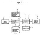
- Fig. 1 is a block diagram of Embodiment 1 of the present invention.
- 1 is input means that is normally a keyboard
- 2 is processing energy determining means.
- 3 is a processing energy database, and as shown in Fig. 3, the processing energy amounts with which the wire will not break are stored corresponding to various combinations of the plate thickness of the workpiece, the upper nozzle height and the lower nozzle height, as percentages of the normal standard processing parameters described above.
- the upper nozzle 70 is separated from the workpiece 72 as shown in part (A) of Fig. 10, for example. This percentage data exists only with regard to the first processing step.
- the processing energy is determined by the processing energy determining means 2 based on the data regarding the plate thickness, the upper nozzle height and the lower nozzle height read out from the processing energy database 3.
- the processing energy data determined by the processing energy determining means 2 is sent to the processing parameter changing means 4.
- 5 is processing parameter storage means that stores the charging voltage, the ON period, the OFF period, the shift amount and the like as standard processing parameters (n steps : n ⁇ 1) during nozzle contact (i.e., when the nozzles are in contact with the workpiece).
- the processing parameter changing means 4 changes the processing parameters sent from the processing parameter storage means based on the processing energy data determined by the processing energy determining means 2, outputs it to a controller 7, or displays the processing parameters on a screen (not shown) of an output/display means 6.
- the nozzle 70 is separated from the workpiece 72 as shown in part (A) of Fig. 10, for example.
- Fig. 2 is a flow chart showing the operation of Embodiment 1 of the present invention.
- the material quality, plate thickness, wire diameter, upper nozzle height, lower nozzle height and the like are input to the processing energy determining means 2 via the input means 1 (ST 1-1).
- the standard processing parameters determined based on the material quality, plate thickness, wire diameter and the like where the nozzles are in contact with the workpiece are stored beforehand in the processing parameter storage means 3, and these standard processing parameters are sent to the processing parameter changing means 4 (ST 1-2).
- the processing energy determining means 2 determines the amount of processing energy from the table stored in the processing energy database 3 and shown in Fig. 3 (ST 2-3).
- Fig. 3 ST 2-3
- the processing energy amount is '0.5' according to No. 2 in Fig. 3, and the processing energy amount is determined as 50% of the standard first-step amount by the processing energy determining means 2.
- the '0.5' information is sent from the processing energy determining means 2 to the processing parameter changing means 4.
- the processing parameter changing means 4 reduces the processing energy amount by 50% by increasing the OFF period.
- the processing parameter changing means 4 changes the standard first-step processing parameters based on the processing energy amount (ST 2-4).
- the changed first-step processing parameters are sent to the controller 7 together with the unchanged processing parameters for the second and subsequent processing steps, and are displayed on the screen (not shown) of the output/display means 6 (ST 1-5).
- the controller 7 performs first-step processing of the workpiece in accordance with the processing parameters.
- processing takes place without a change in the processing parameters. According to this Embodiment 1, because the energy amount is controlled in accordance with the nozzle separation amounts, wire breakage can be prevented.
- the processing energy amount is determined based on the data stored in the processing energy database, but it is also acceptable if it is derived through an approximate expression for an energy amount sought from the nozzle heights and the plate thickness.
- the method in which the processing energy amount is reduced by 50% has been described as a method in which the OFF period is increased, but various other methods may also be used, such as a method in which the ON period is decreased or the servomotor voltage is increased.
- processing energy amount corresponding to the wire nozzle separation amounts is not known, a processing energy amount such as '0.4' may be input directly.
- the method of expression of the energy amount has been described as a percentage of the standard processing parameters for first-step processing, it may also take the form of a value calculated directly as the energy amount within a certain period of time based on the current waveform information such as the ON period, the OFF period or the like. This energy amount expresses the actual energy amount itself.
- the energy amounts shown in Fig. 3 are different in that they are expressed as percentages of the standard processing parameters, as described above.
- Fig. 4 is a block diagram of Embodiment 2 of the present invention, and Fig. 5 is a flow chart showing the operation thereof.
- 1 is the same input means used in Embodiment 1, and a keyboard is normally used therefor.
- 30 is liquid flow rate determining means pertaining to the processing liquid flow rate (hereinafter 'liquid flow rate'), and 31 is a liquid flow rate database.
- liquid flow rates that will not break the wire are stored in this liquid flow rate database 31 as percentages of the standard processing parameters corresponding to various combinations of workpiece plate thickness, upper nozzle height and lower nozzle height. This percentage data pertains to processing for the first processing step only.
- the liquid flow rate determining means 30 determines the liquid flow rate based on the data read out from the liquid flow rate database 31.
- the liquid flow rate data determined by the liquid flow rate determining means 30 is sent to liquid flow rate changing means 32.
- 5 is the same processing parameter storage means used in Embodiment 1, and this means stores such parameters as the charging voltage, the ON period, the OFF period, the shift amount and the liquid flow rate as standard processing parameters (n steps : n ⁇ 1) during nozzle contact (i.e., when the nozzles are in contact with the workpiece).
- the liquid flow rate changing means 32 changes the liquid flow rate (liquid flow rate parameter) sent by the processing parameter storage means 5 based on the liquid flow rate determined by the liquid flow rate determining means 30, and the changed liquid flow rate is output to the controller 7 and displayed on the screen (not shown) of an output/display means 6.
- the material quality, plate thickness, wire diameter, upper nozzle height, lower nozzle height and the like are input to the liquid flow rate determining means 30 via the input means 1 (ST 2-1).
- the standard processing parameters determined based on the material quality, plate thickness, wire diameter and the like where the nozzles are in contact with the workpiece are stored beforehand in the processing parameter storage means 5, and these standard processing parameters are sent to the liquid flow rate changing means 12 (ST 2-2).
- the liquid flow rate determining means 30 determines the liquid flow rate based on the liquid flow rate from the liquid flaw rate database 31 (ST 2-3).
- the liquid flow rate is '0.5' according to No. 2 in Fig. 6, and the liquid flow rate is determined as 50% of the standard first-step amount by the liquid flow rate determining means 30.
- the '50%' information is sent by the liquid flow rate determining means 30 to the liquid flow rate changing means 32.
- the liquid flow rate changing means 32 changes the liquid flow rate for the standard first-step processing (the liquid flow rate parameter) (ST 2-4).
- the changed first-step liquid flow rate is sent to the controller 33 together with the unchanged processing parameters for the second and subsequent processing steps, and is displayed on the screen (not shown) of the output/display means 6 (ST 2-5).
- the controller 33 performs first-step processing of the workpiece in accordance with the changed liquid flow rate. During the second and subsequent processing steps, because one side of the wire is open and is not affected by the liquid flow rate, processing takes place without a change in the liquid flow rate.
- the processing liquid flows smoothly and wire breakage is prevented.
- wire breakage is less likely if the upper nozzle liquid amount is about half the normal value.
- this Embodiment 2 because the processing liquid amount is controlled in accordance with the nozzle separation amounts, wire breakage can be prevented.
- liquid flow rate has been described as being stored in the liquid flow rate database 31, but it is also acceptable if it is derived through an approximate expression for a liquid flow rate sought from the nozzle heights and the plate thickness.
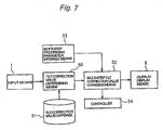
- Fig. 7 is a block diagram showing Embodiment 3 of the present invention
- Fig. 8 is a flow chart showing the operation thereof.
- 1 is the same input means, and is normally a keyboard as in Embodiment 1.
- 50 is tilt correction value determining means
- 51 is a tilt correction value database.
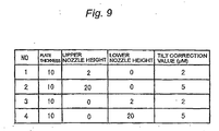
- accuracy-compensating wire tilt correction values corresponding to various combinations of workpiece plate thickness, upper nozzle height and lower nozzle height are stored as wire tilt correction values for all processing steps in normal standard processing.
- the tilt correction value determining means 50 determines the wire tilt correction value based on the data read out from the tilt correction value database 51.
- the tilt correction value data determined by the tilt correction value determining means 50 is sent to a multi-step tilt correction value changing means 52.
- the multi-step tilt correction value changing means 52 changes the processing parameter (wire tilt parameter) sent from the multi-step processing parameter storage means 53 based on the tilt correction value determined by the tilt correction value determining means 50, outputs it to the controller 54, and displays the tilt correction value on the screen (not shown) of an output/display means 6.
- Embodiment 3 The operation of Embodiment 3 will now be described with reference to Fig. 8.
- the material quality, plate thickness, wire diameter, upper nozzle height, lower nozzle height and the like are input via the input means 1 (ST 3-1).
- the standard processing parameters determined based on the material quality, plate thickness, wire diameter and the like where the nozzles are in contact with the workpiece are stored beforehand in the multi-step processing parameter storage means 53, and these standard processing parameters are sent to the multi-step tilt correction value changing means 52 (ST 3-2).
- the tilt correction value determining means 50 determines the tilt correction value based on the tilt correction value sent from the tilt correction value database 51 (ST 3-3).
- the tilt correction value is '5' according to No. 2 in Fig. 9, and this '5' information is sent by the tilt correction value determining means 50 to the multi-step tilt correction value changing means 52.
- the multi-step tilt correction value changing means 52 changes the processing parameter, i.e., the tilt (tilt parameter) for the first through n th steps of standard processing using the tilt correction value 5 (ST 3-4).
- the changed processing parameters for the first through n th steps are sent to the controller 54, and are displayed on the screen (not shown) of an output/display means 6 (ST 3-5).
- the controller 54 performs first-step through n th -step processing of the workpiece with the wire tilted, in accordance with the processing parameters.
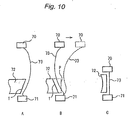
- Fig. 10 is an image drawing showing situations in which one of the nozzles is separated from the workpiece.
- Part (C) of the drawing shows the case where the upper nozzle 70 and the lower nozzle 71 are in contact with the workpiece 72, while the solid lines in parts (A) and (B) show the case in which the upper nozzle 70 is separated from the workpiece 72, the wire 73 warps as a result, causing a tapered surface T to be formed in the workpiece 72 due to discharge repulsion force or electrostatic force.
- the surface of the workpiece can be finished via processing into the vertical surface P.
- the wire tilt amount for all processing steps is corrected using the same tilt correction value as that saved in the tilt correction value database 51, but it is also acceptable if, for example, correction is performed for only the n th step, or if a separate tilt correction value is used for the first step, the second step, etc., up to the n th step.
- wire tilt correction value has been described as being stored in the tilt correction value database 51, it may also be derived through an approximate expression for the wire tilt correction value sought from the nozzle heights and the plate thickness.
- the wire tilt correction value has been described as included in the processing parameters, it is also acceptable if the wire tilt correction value is stored in a different form from the processing parameters so long as the wire tilt can be corrected during processing.
- the processing parameters and liquid flow rate are adjusted so as to prevent breakage of the wire during the first processing step, but in Embodiment 3, the surface precision and configuration accuracy of the processed surface can be improved.
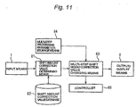
- Fig. 11 is a block diagram showing Embodiment 4 of the present invention
- Fig. 12 is a flow chart showing the operation thereof
- 1 is input means, and is normally a keyboard as in Embodiment 1.
- 81 is shift amount correction value determining means
- 82 is a shift amount correction value database.
- this database stores wire shift amount correction values for the accuracy-compensating second processing step corresponding to various combinations of workpiece plate thickness, upper nozzle height and lower nozzle height as correction values for the shift amount, which is one of the above normal standard processing parameters for the second processing step.
- the shift amount correction value determining means 81 determines the shift amount correction value based on the data read out from the shift amount correction value database 82.
- the shift amount correction value data determined by the shift amount correction value determining means 81 is sent to the multi-step shift amount correction value changing means 83.
- 84 is a multi-step processing parameter storage means, which stores such parameters as the charging voltage, the ON period, the OFF period, and the shift amount as standard processing parameters (n steps : n ⁇ 1) during nozzle contact (i.e., when the nozzles are in contact with the workpiece).
- the multi-step shift amount correction value changing means 83 changes the shift amount parameter correction value for the second processing step sent from the multi-step processing parameter storage means 84 based on the shift amount correction value determined by the shift amount correction value determining means 81, outputs it to the controller 85, and displays the shift amount correction value on the screen (not shown) of an output/display means 6.
- Embodiment 4 The operation of Embodiment 4 will now be described with reference to Fig. 12.
- the material quality, plate thickness, wire diameter, upper nozzle height, lower nozzle height and the like are input via the input means 1 (ST 4-1).
- the standard processing parameters determined based on the material quality, plate thickness, wire diameter and the like where the nozzles are in contact with the workpiece are stored beforehand in the multi-step processing parameter storage means 84, and these standard processing parameters are sent to the multi-step shift amount changing means 83 (ST 4-2).
- the multi-step shift amount determining means 81 determines the shift amount correction value based on the shift amount correction value sent from the shift amount correction value database 82.
- the shift amount correction value is'10' according to No. 2 in Fig. 13, and the shift amount correction value for the second processing step of standard processing is determined to be '10' (ST 4-3).
- This '10' information is sent from the shift amount correction value determining means 81 to the multi-step shift amount correction value changing means 83.
- the multi-step shift amount correction value changing means 83 changes the shift amount, one of the processing parameters for the second processing step, using the shift amount correction value (ST 4-4).
- the processing parameters for the second processing step in which the shift amount has been changed are sent to the controller 85 together with the processing parameters for the first processing step and the processing parameters for the third and subsequent steps, and are output and displayed on the screen (not shown) of the display means 6 (ST 4-5).
- the controller 85 performs processing in accordance with the processing parameters.
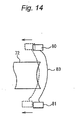
- Fig. 14 is an image drawing showing the situation in which the upper nozzle 80 and the lower nozzle 81 are separated from the workpiece. Where the nozzles are separated, warp is caused in the wire 83, and when the second processing step is performed, if the wire 73 is in the position indicated by the solid line, discharge no longer takes place in the center of the workpiece because the processed surface of the workpiece 72 becomes concave. Accordingly, by moving the upper nozzle 80 and the lower nozzle 81 in the direction of the arrow to the positions indicated by the dotted lines to change the shift amount, processing accuracy can be improved.
- the shift amount is the distance by which the upper nozzle 80 and the lower nozzle 81 are shifted by the same distance (from the positions of the wire and nozzles indicated by the solid lines to the positions indicated by the dotted lines).
- shift amount correction value for the second processing step is held in the database in Embodiment 4, it is also acceptable if correction is performed only for a different processing step, or if a separate correction value is held for each individual processing step, such as for the first, second, and nth processing step.
- the shift amount may be changed if the ON period, processing conveyance speed, discharge voltage or the like is changed.
- Fig. 15 is a block diagram showing Embodiment 5 of the present invention
- Fig. 16 is a flow chart showing the operation thereof.
- 1 is input means, and is normally a keyboard as in Embodiment 1.
- 100 is nozzle height detection means that automatically seeks the nozzle heights
- 101 is a processing speed database that stores the relationship between the processing speed and the nozzle separation amounts
- 81 is shift amount correction value determining means.
- 82 is a shift amount correction value database, which stores, as shown in Fig. 17, shift amount correction values for the accuracy-compensating second processing step corresponding to various combinations of workpiece plate thickness, upper nozzle height and lower nozzle height as shift amount correction values for the shift amount, which is one of the above normal standard processing parameters for the second processing step.
- the shift amount correction value determining means 81 determines the shift amount correction value based on the data read out from the shift amount correction value database 82.
- the shift amount correction value data determined by the shift amount correction value determining means 81 is sent to the multi-step shift amount correction value changing means 83.
- 84 is a multi-step processing parameter storage means, which stores such parameters as the charging voltage, the ON period, the OFF period, the shift amount and the like as standard processing parameters (n steps : n ⁇ 1) during nozzle contact (i.e., when the nozzles are in contact with the workpiece).
- the multi-step shift amount correction value changing means 83 changes the shift amount correction value for the second processing step sent from the multi-step processing parameter storage means 84 based on the shift amount correction value determined by the shift amount correction value determining means 81, outputs it to the controller 85, and displays the shift amount correction value on the screen (not shown) of an output/display means 6.
- Embodiment 5 The operation of Embodiment 5 will now be described with reference to Fig. 16.
- the material quality, plate thickness, wire diameter, and the like are input via the input means 1 (ST 5-1).
- the standard processing parameters determined based on the material quality, plate thickness, wire diameter and the like where the nozzles are in contact with the workpiece are stored beforehand in the multi-step processing parameter storage means 84, and these standard processing parameters are sent to the multi-step shift amount changing means 83. Processing is then begun (ST 5-2).
- the nozzle height detection means 100 detects the processing speed and extracts the nozzle heights from the processing speed database 101 shown in Fig.
- Fig. 18 shows a display screen, on which are displayed the upper nozzle 70, the lower nozzle 71, the workplace 72 and spaces 75 and 76 in which are input the heights of the upper nozzle and the lower nozzle.
- this value '20' is converted to coordinate data on the display screen, and the upper nozzle 70 is displayed at a position where the upper nozzle height is 20mm.
- the shift amount correction value determining means 81 determines the shift amount correction value based on the shift amount correction values in the shift amount correction value database 82 (ST 5-6).
- the shift amount correction value is '10' according to No. 2 in Fig. 13, and the shift amount correction value for the second processing step of standard processing is determined to be '10'.
- This '10' information is sent from the shift amount correction value determining means 81 to the multi-step shift amount correction value changing means 83.
- the multi-step shift amount correction value changing means 83 changes the shift amount, one of the processing parameters for the second processing step of standard processing, using the shift amount correction value (ST 5-7).
- the processing parameters for the second step in which the shift amount has been changed are sent to the controller 85 together with the processing parameters for the first processing step and the processing parameters for the third and subsequent steps, and are displayed on the screen (not shown) of the outputldisplay means 6 (ST 5-8).
- the controller 85 performs processing in accordance with the processing parameters.
- the detected nozzle heights are displayed on the display means in Embodiment 5, it is also acceptable if such display is performed when the user inputs the nozzle heights in Embodiments 1-4.
- the user inputs '20' for the nozzle height as shown in part (B) of Fig. 18, when the initial state shown in part (A) is being displayed, the value '20' is converted to coordinate data on the display screen, such that a graphic image in which the upper nozzle has moved to a position 20 mm higher is displayed based on the converted values, as shown in part (C).
- input is performed by the user via a keyboard, but it is acceptable if different input means is used, or if values are input from an external system or the like that automatical measures nozzle heights.
- Embodiment 5 because the processing state is detected as the processing speed, correction in accordance with the nozzle heights is automatically performed even if data such as nozzle heights is not input by the user, enabling surface precision to be improved.
- the constituent elements have been described as provided within the wire-electrical discharge machine, they may be provided in a CAD/CAM system separate from the wire-electrical discharge machine, for example. Such a situation is also included in the scope of the present invention, with the understanding that the wire-electrical discharge machine encompasses the separate CAD/CAM system.
- the present invention prevents wire breakage in a wire-electrical discharge machine, and increases the surface precision and configuration accuracy of the processed surface, it can be advantageously used in wire-electrical discharge machining.
Landscapes
- Engineering & Computer Science (AREA)
- Chemical & Material Sciences (AREA)
- Chemical Kinetics & Catalysis (AREA)
- Electrochemistry (AREA)
- Mechanical Engineering (AREA)
- Automation & Control Theory (AREA)
- Electrical Discharge Machining, Electrochemical Machining, And Combined Machining (AREA)
Abstract
A wire-electrical discharge machine infuses a processing liquid in a gap
between a wire and a workpiece and processes the workpiece using predetermined
processing parameters. The machine includes processing parameter storage
means that stores processing parameters, means that stores a relationship between
the nozzle heights and the amount of processing energy, processing energy
determining means that determines the amount of processing energy, for example,
during rough processing based on such relationship, and processing parameter
changing means that changes the processing parameters based on the amount of
processing energy. The workpiece is processed using the changed processing
parameters. According to this construction, wire breakage can be prevented and
the accuracy of the processed surface can be improved.
Description
The present invention relates to a wire-electrical discharge machine.
Generally, wire-electrical discharge machining involves three to seven
processing steps that include rough processing, intermediate processing, semi-finishing,
and finishing, wherein the processing is performed while reducing the
amount of energy. The purpose of this is to reduce the processing time by
gradually reducing the surface roughness, as well as to increase the precision of the
straightness of the processed surface. Furthermore, it is known that during wire
electrical discharge machining, due to wire vibration caused by discharge repulsion,
electrostatic force or the like, the part of the wire facing the center part of a workpiece
may become dented, or may swell into a so-called 'drum shape'. Furthermore, the
processing conditions are completely different between the first processing step
(rough processing) and the subsequent processing steps (intermediate processing,
semi-finishing, and finishing). In the first processing step, because processing is
performed on a virgin workpiece, there is a danger that processing debris will not be
adequately eliminated from the workpiece, and that the wire may break due to the
presence of the debris.
Fig. 19 depicts a conventional wire-electrical discharge machine as
disclosed in Japanese Patent Publication No. 7-16825, which includes input means
120 for inputting the plate thickness of a workpiece, the heights of nozzles and the
like, processing parameter storage means 121 that stores the charging voltage, the
ON period, the OFF period and the like, liquid pressure calculation means 122 that
calculates the nozzle liquid pressure from the nozzle heights and other parameters,
and processing parameter changing means 123 that changes the processing
parameters based on the calculated nozzle liquid pressure, and seeks the nozzle
liquid pressure, i.e., the processing liquid pressure, based on the nozzle heights, and
changes the processing parameters based on the processing liquid pressure. In
the first processing step, however, if the nozzles are sufficiently distanced from the
workpiece, wire breakage is caused not by the liquid pressure during processing but
by the wire length. It is therefore difficult to reliably prevent breakage of the wire
using the method in which the processing parameters are calculated from the
processing liquid pressure. In actual experiments, it has been determined that
where the distance between the upper nozzle and the workpiece was 2 mm, (with a
plate thickness of 20 mm and a wire having a diameter of 0.25 mm), the processing
liquid pressure varies, but where the distance is longer than it, there is no change in
processing liquid pressure. However, the problem arises that when the wire is long,
it warps easily, and it is difficult to perform control when a short-circuit occurs,
resulting in an increased likelihood of wire breakage. The present invention has
been developed to solve the above-described problems, and an object thereof is to
provide a wire-electrical discharge machine wherein the wire is not likely to break
even where the nozzles are located at a distance from the workpiece. Furthermore,
while the surface precision of the processed surface and processing accuracy are
important in wire-electrical discharge machining, such processing accuracy is not
taken into account in the conventional art.
The wire-electrical discharge machine according to a first aspect of the
present invention includes processing parameter storage means that stores
processing parameters, means that stores a relationship between a nozzle height
and an amount of processing energy, processing energy determining means that
determines the amount of processing energy during rough processing based on such
relationship, and processing parameter changing means that changes the
processing parameters based on the amount of processing energy. The workpiece
is processed using the changed processing parameters. According to this
construction, because the amount of processing energy is determined based on the
wire nozzle height, the wire is not likely to break even where the nozzle is located at
a far distance.
The wire-electrical discharge machine according to a second aspect of
the present invention includes processing parameter storage means that stores
standard processing parameters, means that stores a relationship between a nozzle
height and an amount of liquid flow, means that determines the amount of liquid flow
during rough processing based on such relationship, and liquid flow rate changing
means that changes a liquid flow rate parameter among the processing parameters.
The workpiece is processed using the changed processing parameters. According
to this construction, because the processing liquid flow rate is determined in
accordance with the nozzle height, the wire is not likely to break.
The wire-electrical discharge machine according to a third aspect of the
present invention includes processing parameter storage means that stores standard
processing parameters, means that stores a relationship between a nozzle height
and an amount of wire tilt, tilt correction value determining means that determines the
amount of wire tilt during processing based on such relationship, and tilt correction
value changing means that changes a tilt correction value parameter among the
processing parameters. The workpiece is processed using the changed processing
parameters. According to this construction, the tilt caused by warping of the wire is
corrected, thereby increasing surface precision and processing accuracy.
The wire-electrical discharge machine according to a fourth aspect of
the present invention includes processing parameter storage means that stores
standard processing parameters, means that stores a relationship between a nozzle
height and an amount of wire shift, shift amount correction value determining means
that determines the amount of wire shift during processing based on such
relationship, and shift amount changing means that changes a wire shift amount
parameter among the processing parameters. The workpiece is processed using
the changed processing parameters. According to this construction, the amount of
wire shift takes into account the degree of warping of the wire, thereby improving
surface precision.
The wire-electrical discharge machine according to a fifth aspect of the
present invention includes processing parameter storage means that stores standard
processing parameters, nozzle distance detection means that detects a processing
state in a first processing step and detects a nozzle distance from the detected
processing state, and processing parameter determining means that determines the
processing parameters for subsequent processing steps based on the detected
nozzle distance. The workplace is processed using the determined processing
parameters. According to this construction, because the correct nozzle height can
be automatically detected and correction can be performed in accordance with such
nozzle height, surface precision can be improved.
In the wire-electrical discharge machine according to the fifth aspect of
the present invention, the wire-electrical discharge machine according to a sixth
aspect of the present invention detects the processing speed as the processing state.
According to this construction, surface precision is improved.
In the wire-electrical discharge machine according to the fifth aspect of
the present invention, the wire-electrical discharge machine according to a seventh
aspect of the present invention further includes means for displaying a state of
separation of a wire nozzle in a graphical fashion. According to this construction,
errors during setting or inputting can be prevented.
Embodiments of the present invention will be described below with
reference to the drawings. In the drawings, identical or equivalent components are
assigned the same symbols, and explanation thereof will be omitted.
Fig. 1 is a block diagram of Embodiment 1 of the present invention. In
the drawing, 1 is input means that is normally a keyboard, and 2 is processing
energy determining means. 3 is a processing energy database, and as shown in
Fig. 3, the processing energy amounts with which the wire will not break are stored
corresponding to various combinations of the plate thickness of the workpiece, the
upper nozzle height and the lower nozzle height, as percentages of the normal
standard processing parameters described above. Regarding the nozzle heights,
the upper nozzle 70 is separated from the workpiece 72 as shown in part (A) of Fig.
10, for example. This percentage data exists only with regard to the first processing
step. The processing energy is determined by the processing energy determining
means 2 based on the data regarding the plate thickness, the upper nozzle height
and the lower nozzle height read out from the processing energy database 3. The
processing energy data determined by the processing energy determining means 2
is sent to the processing parameter changing means 4. 5 is processing parameter
storage means that stores the charging voltage, the ON period, the OFF period, the
shift amount and the like as standard processing parameters (n steps : n≥ 1) during
nozzle contact (i.e., when the nozzles are in contact with the workpiece). The
processing parameter changing means 4 changes the processing parameters sent
from the processing parameter storage means based on the processing energy data
determined by the processing energy determining means 2, outputs it to a controller
7, or displays the processing parameters on a screen (not shown) of an
output/display means 6. Here, regarding the nozzle heights, the nozzle 70 is
separated from the workpiece 72 as shown in part (A) of Fig. 10, for example.
Fig. 2 is a flow chart showing the operation of Embodiment 1 of the
present invention.
The first operation will now be explained with reference to Fig. 2. The
material quality, plate thickness, wire diameter, upper nozzle height, lower nozzle
height and the like are input to the processing energy determining means 2 via the
input means 1 (ST 1-1). The standard processing parameters determined based on
the material quality, plate thickness, wire diameter and the like where the nozzles are
in contact with the workpiece are stored beforehand in the processing parameter
storage means 3, and these standard processing parameters are sent to the
processing parameter changing means 4 (ST 1-2). Based on the material quality,
plate thickness, wire diameter, upper nozzle height, lower nozzle height and the like
input by the input means 1, the processing energy determining means 2 determines
the amount of processing energy from the table stored in the processing energy
database 3 and shown in Fig. 3 (ST 2-3). In Fig. 3, where the plate thickness is '10',
the upper nozzle separation amount is '20' and the lower nozzle separation amount
is '0', for example, the processing energy amount is '0.5' according to No. 2 in Fig. 3,
and the processing energy amount is determined as 50% of the standard first-step
amount by the processing energy determining means 2. The '0.5' information is
sent from the processing energy determining means 2 to the processing parameter
changing means 4. The processing parameter changing means 4 reduces the
processing energy amount by 50% by increasing the OFF period. The processing
parameter changing means 4 changes the standard first-step processing parameters
based on the processing energy amount (ST 2-4). The changed first-step
processing parameters are sent to the controller 7 together with the unchanged
processing parameters for the second and subsequent processing steps, and are
displayed on the screen (not shown) of the output/display means 6 (ST 1-5). The
controller 7 performs first-step processing of the workpiece in accordance with the
processing parameters. During the second and subsequent processing steps,
because there is no need to reduce the processing energy level since the wire will
not break, processing takes place without a change in the processing parameters.
According to this Embodiment 1, because the energy amount is controlled in
accordance with the nozzle separation amounts, wire breakage can be prevented.
In Embodiment 1, the processing energy amount is determined based
on the data stored in the processing energy database, but it is also acceptable if it is
derived through an approximate expression for an energy amount sought from the
nozzle heights and the plate thickness.
The method in which the processing energy amount is reduced by 50%
has been described as a method in which the OFF period is increased, but various
other methods may also be used, such as a method in which the ON period is
decreased or the servomotor voltage is increased.
Where the processing energy amount corresponding to the wire nozzle
separation amounts is not known, a processing energy amount such as '0.4' may be
input directly.
While standard processing parameters have been described as being
stored beforehand in the processing parameter storage means 5, it is acceptable if
the standard processing parameters are determined by different means, such as
through user input.
While the method of expression of the energy amount has been
described as a percentage of the standard processing parameters for first-step
processing, it may also take the form of a value calculated directly as the energy
amount within a certain period of time based on the current waveform information
such as the ON period, the OFF period or the like. This energy amount expresses
the actual energy amount itself. On the other hand, the energy amounts shown in
Fig. 3 are different in that they are expressed as percentages of the standard
processing parameters, as described above.
Fig. 4 is a block diagram of Embodiment 2 of the present invention, and
Fig. 5 is a flow chart showing the operation thereof. In Fig. 4, 1 is the same input
means used in Embodiment 1, and a keyboard is normally used therefor. 30 is
liquid flow rate determining means pertaining to the processing liquid flow rate
(hereinafter 'liquid flow rate'), and 31 is a liquid flow rate database. As shown in Fig.
6, liquid flow rates that will not break the wire are stored in this liquid flow rate
database 31 as percentages of the standard processing parameters corresponding
to various combinations of workpiece plate thickness, upper nozzle height and lower
nozzle height. This percentage data pertains to processing for the first processing
step only. The liquid flow rate determining means 30 determines the liquid flow rate
based on the data read out from the liquid flow rate database 31. The liquid flow
rate data determined by the liquid flow rate determining means 30 is sent to liquid
flow rate changing means 32. 5 is the same processing parameter storage means
used in Embodiment 1, and this means stores such parameters as the charging
voltage, the ON period, the OFF period, the shift amount and the liquid flow rate as
standard processing parameters (n steps : n ≥1) during nozzle contact (i.e., when
the nozzles are in contact with the workpiece). The liquid flow rate changing means
32 changes the liquid flow rate (liquid flow rate parameter) sent by the processing
parameter storage means 5 based on the liquid flow rate determined by the liquid
flow rate determining means 30, and the changed liquid flow rate is output to the
controller 7 and displayed on the screen (not shown) of an output/display means 6.
The processing operation of the first processing step will now be
described with reference to Fig. 5. The material quality, plate thickness, wire
diameter, upper nozzle height, lower nozzle height and the like are input to the liquid
flow rate determining means 30 via the input means 1 (ST 2-1). The standard
processing parameters determined based on the material quality, plate thickness,
wire diameter and the like where the nozzles are in contact with the workpiece are
stored beforehand in the processing parameter storage means 5, and these
standard processing parameters are sent to the liquid flow rate changing means 12
(ST 2-2). When the material quality, plate thickness, wire diameter, upper nozzle
height, lower nozzle height and the like are input using the input means 1, the liquid
flow rate determining means 30 determines the liquid flow rate based on the liquid
flow rate from the liquid flaw rate database 31 (ST 2-3). For example, where the
plate thickness is '10', the upper nozzle separation amount is '20' and the lower
nozzle separation amount is '0', the liquid flow rate is '0.5' according to No. 2 in Fig. 6,
and the liquid flow rate is determined as 50% of the standard first-step amount by the
liquid flow rate determining means 30. The '50%' information is sent by the liquid
flow rate determining means 30 to the liquid flow rate changing means 32. Based
on the liquid flow rate sent by the processing parameter storage means 5, the liquid
flow rate changing means 32 changes the liquid flow rate for the standard first-step
processing (the liquid flow rate parameter) (ST 2-4). The changed first-step liquid
flow rate is sent to the controller 33 together with the unchanged processing
parameters for the second and subsequent processing steps, and is displayed on the
screen (not shown) of the output/display means 6 (ST 2-5). The controller 33
performs first-step processing of the workpiece in accordance with the changed
liquid flow rate. During the second and subsequent processing steps, because one
side of the wire is open and is not affected by the liquid flow rate, processing takes
place without a change in the liquid flow rate.
By adjusting the liquid flow rate, the processing liquid flows smoothly
and wire breakage is prevented. For example, it is known that where the upper
nozzle is separated from the workpiece, wire breakage is less likely if the upper
nozzle liquid amount is about half the normal value. According to this Embodiment
2, because the processing liquid amount is controlled in accordance with the nozzle
separation amounts, wire breakage can be prevented.
The liquid flow rate has been described as being stored in the liquid
flow rate database 31, but it is also acceptable if it is derived through an approximate
expression for a liquid flow rate sought from the nozzle heights and the plate
thickness.
Furthermore, while standard processing parameters have been
described as being stored beforehand in the processing parameter storage means 5,
it is acceptable if the standard processing parameters are determined by different
means, such as through user input.
Fig. 7 is a block diagram showing Embodiment 3 of the present
invention, and Fig. 8 is a flow chart showing the operation thereof. In Fig. 7, 1 is the
same input means, and is normally a keyboard as in Embodiment 1. 50 is tilt
correction value determining means, and 51 is a tilt correction value database. As
shown in Fig. 9, accuracy-compensating wire tilt correction values corresponding to
various combinations of workpiece plate thickness, upper nozzle height and lower
nozzle height are stored as wire tilt correction values for all processing steps in
normal standard processing. The tilt correction value determining means 50
determines the wire tilt correction value based on the data read out from the tilt
correction value database 51. The tilt correction value data determined by the tilt
correction value determining means 50 is sent to a multi-step tilt correction value
changing means 52. 53 is a multi-step processing parameter storage means, which
stores such parameters as the charging voltage, the ON period, the OFF period, the
shift amount and the tilt of the wire as standard processing parameters (n steps : n ≥
1) during nozzle contact (i.e., when the nozzles are in contact with the workpiece).
The multi-step tilt correction value changing means 52 changes the processing
parameter (wire tilt parameter) sent from the multi-step processing parameter
storage means 53 based on the tilt correction value determined by the tilt correction
value determining means 50, outputs it to the controller 54, and displays the tilt
correction value on the screen (not shown) of an output/display means 6.
The operation of Embodiment 3 will now be described with reference to
Fig. 8. The material quality, plate thickness, wire diameter, upper nozzle height,
lower nozzle height and the like are input via the input means 1 (ST 3-1). The
standard processing parameters determined based on the material quality, plate
thickness, wire diameter and the like where the nozzles are in contact with the
workpiece are stored beforehand in the multi-step processing parameter storage
means 53, and these standard processing parameters are sent to the multi-step tilt
correction value changing means 52 (ST 3-2). When the material quality, plate
thickness, wire diameter, upper nozzle height, lower nozzle height and the like are
input using the input means 1, the tilt correction value determining means 50
determines the tilt correction value based on the tilt correction value sent from the tilt
correction value database 51 (ST 3-3). For example, where the plate thickness is
'10'. the upper nozzle separation amount is '20' and the lower nozzle separation
amount is '0', the tilt correction value is '5' according to No. 2 in Fig. 9, and this '5'
information is sent by the tilt correction value determining means 50 to the multi-step
tilt correction value changing means 52. The multi-step tilt correction value
changing means 52 changes the processing parameter, i.e., the tilt (tilt parameter)
for the first through nth steps of standard processing using the tilt correction value 5
(ST 3-4). The changed processing parameters for the first through nth steps are
sent to the controller 54, and are displayed on the screen (not shown) of an
output/display means 6 (ST 3-5). The controller 54 performs first-step through nth-step
processing of the workpiece with the wire tilted, in accordance with the
processing parameters.
Fig. 10 is an image drawing showing situations in which one of the
nozzles is separated from the workpiece. Part (C) of the drawing shows the case
where the upper nozzle 70 and the lower nozzle 71 are in contact with the workpiece
72, while the solid lines in parts (A) and (B) show the case in which the upper nozzle
70 is separated from the workpiece 72, the wire 73 warps as a result, causing a
tapered surface T to be formed in the workpiece 72 due to discharge repulsion force
or electrostatic force. Accordingly, in the case shown in part (B) of the drawing, for
example, by moving the upper nozzle 70 outward in the direction of the arrow and
tilting the wire 73 by the angle e corresponding to the tilt correction value of the wire
73, as shown by the dotted line, the surface of the workpiece can be finished via
processing into the vertical surface P. While in Embodiment 3, the wire tilt amount
for all processing steps is corrected using the same tilt correction value as that saved
in the tilt correction value database 51, but it is also acceptable if, for example,
correction is performed for only the nth step, or if a separate tilt correction value is
used for the first step, the second step, etc., up to the nth step.
Moreover, while the wire tilt correction value has been described as
being stored in the tilt correction value database 51, it may also be derived through
an approximate expression for the wire tilt correction value sought from the nozzle
heights and the plate thickness.
Furthermore, while in Embodiment 3 the wire tilt correction value has
been described as included in the processing parameters, it is also acceptable if the
wire tilt correction value is stored in a different form from the processing parameters
so long as the wire tilt can be corrected during processing.
In Embodiments 1 and 2 described above, the processing parameters
and liquid flow rate are adjusted so as to prevent breakage of the wire during the first
processing step, but in Embodiment 3, the surface precision and configuration
accuracy of the processed surface can be improved.
Fig. 11 is a block diagram showing Embodiment 4 of the present
invention, and Fig. 12 is a flow chart showing the operation thereof In Fig. 11, 1 is
input means, and is normally a keyboard as in Embodiment 1. 81 is shift amount
correction value determining means, and 82 is a shift amount correction value
database. As shown in Fig. 13, this database stores wire shift amount correction
values for the accuracy-compensating second processing step corresponding to
various combinations of workpiece plate thickness, upper nozzle height and lower
nozzle height as correction values for the shift amount, which is one of the above
normal standard processing parameters for the second processing step. The shift
amount correction value determining means 81 determines the shift amount
correction value based on the data read out from the shift amount correction value
database 82. The shift amount correction value data determined by the shift
amount correction value determining means 81 is sent to the multi-step shift amount
correction value changing means 83. 84 is a multi-step processing parameter
storage means, which stores such parameters as the charging voltage, the ON
period, the OFF period, and the shift amount as standard processing parameters (n
steps : n ≥ 1) during nozzle contact (i.e., when the nozzles are in contact with the
workpiece). The multi-step shift amount correction value changing means 83
changes the shift amount parameter correction value for the second processing step
sent from the multi-step processing parameter storage means 84 based on the shift
amount correction value determined by the shift amount correction value determining
means 81, outputs it to the controller 85, and displays the shift amount correction
value on the screen (not shown) of an output/display means 6.
The operation of Embodiment 4 will now be described with reference to
Fig. 12. The material quality, plate thickness, wire diameter, upper nozzle height,
lower nozzle height and the like are input via the input means 1 (ST 4-1). The
standard processing parameters determined based on the material quality, plate
thickness, wire diameter and the like where the nozzles are in contact with the
workpiece are stored beforehand in the multi-step processing parameter storage
means 84, and these standard processing parameters are sent to the multi-step shift
amount changing means 83 (ST 4-2). When the material quality, plate thickness,
wire diameter, upper nozzle height, lower nozzle height and the like are input using
the input means 1, the multi-step shift amount determining means 81 determines the
shift amount correction value based on the shift amount correction value sent from
the shift amount correction value database 82. For example, where the plate
thickness is '10', the upper nozzle separation amount is '20' and the lower nozzle
separation amount is '0', the shift amount correction value is'10' according to No. 2 in
Fig. 13, and the shift amount correction value for the second processing step of
standard processing is determined to be '10' (ST 4-3). This '10' information is sent
from the shift amount correction value determining means 81 to the multi-step shift
amount correction value changing means 83. The multi-step shift amount
correction value changing means 83 changes the shift amount, one of the processing
parameters for the second processing step, using the shift amount correction value
(ST 4-4). The processing parameters for the second processing step in which the
shift amount has been changed are sent to the controller 85 together with the
processing parameters for the first processing step and the processing parameters
for the third and subsequent steps, and are output and displayed on the screen (not
shown) of the display means 6 (ST 4-5). The controller 85 performs processing in
accordance with the processing parameters.
Fig. 14 is an image drawing showing the situation in which the upper
nozzle 80 and the lower nozzle 81 are separated from the workpiece. Where the
nozzles are separated, warp is caused in the wire 83, and when the second
processing step is performed, if the wire 73 is in the position indicated by the solid
line, discharge no longer takes place in the center of the workpiece because the
processed surface of the workpiece 72 becomes concave. Accordingly, by moving
the upper nozzle 80 and the lower nozzle 81 in the direction of the arrow to the
positions indicated by the dotted lines to change the shift amount, processing
accuracy can be improved. Here, as shown in Fig. 14, the shift amount is the
distance by which the upper nozzle 80 and the lower nozzle 81 are shifted by the
same distance (from the positions of the wire and nozzles indicated by the solid lines
to the positions indicated by the dotted lines).
While the shift amount correction value for the second processing step
is held in the database in Embodiment 4, it is also acceptable if correction is
performed only for a different processing step, or if a separate correction value is
held for each individual processing step, such as for the first, second, and nth
processing step.
It is furthermore acceptable in Embodiment 4 if other processing
parameters that affect the shift amount are changed. For example, the shift amount
may be changed if the ON period, processing conveyance speed, discharge voltage
or the like is changed.
Fig. 15 is a block diagram showing Embodiment 5 of the present
invention, and Fig. 16 is a flow chart showing the operation thereof. In Fig. 15, 1 is
input means, and is normally a keyboard as in Embodiment 1. 100 is nozzle height
detection means that automatically seeks the nozzle heights, 101 is a processing
speed database that stores the relationship between the processing speed and the
nozzle separation amounts, and 81 is shift amount correction value determining
means. 82 is a shift amount correction value database, which stores, as shown in
Fig. 17, shift amount correction values for the accuracy-compensating second
processing step corresponding to various combinations of workpiece plate thickness,
upper nozzle height and lower nozzle height as shift amount correction values for the
shift amount, which is one of the above normal standard processing parameters for
the second processing step. The shift amount correction value determining means
81 determines the shift amount correction value based on the data read out from the
shift amount correction value database 82. The shift amount correction value data
determined by the shift amount correction value determining means 81 is sent to the
multi-step shift amount correction value changing means 83. 84 is a multi-step
processing parameter storage means, which stores such parameters as the charging
voltage, the ON period, the OFF period, the shift amount and the like as standard
processing parameters (n steps : n ≥ 1) during nozzle contact (i.e., when the nozzles
are in contact with the workpiece). The multi-step shift amount correction value
changing means 83 changes the shift amount correction value for the second
processing step sent from the multi-step processing parameter storage means 84
based on the shift amount correction value determined by the shift amount correction
value determining means 81, outputs it to the controller 85, and displays the shift
amount correction value on the screen (not shown) of an output/display means 6.
The operation of Embodiment 5 will now be described with reference to
Fig. 16. The material quality, plate thickness, wire diameter, and the like are input
via the input means 1 (ST 5-1). The standard processing parameters determined
based on the material quality, plate thickness, wire diameter and the like where the
nozzles are in contact with the workpiece are stored beforehand in the multi-step
processing parameter storage means 84, and these standard processing parameters
are sent to the multi-step shift amount changing means 83. Processing is then
begun (ST 5-2). During the first processing step, the nozzle height detection means
100 detects the processing speed and extracts the nozzle heights from the
processing speed database 101 shown in Fig. 15 (ST 5-4), and the nozzle heights
are displayed on the screen (not shown) of the display means 6, as shown in part (C)
of Fig. 18 (ST 5-5). Here, Fig. 18 shows a display screen, on which are displayed
the upper nozzle 70, the lower nozzle 71, the workplace 72 and spaces 75 and 76 in
which are input the heights of the upper nozzle and the lower nozzle. When the
value '20' is displayed in the space 75, as shown in part (C), this value '20' is
converted to coordinate data on the display screen, and the upper nozzle 70 is
displayed at a position where the upper nozzle height is 20mm. It is known that
when the nozzles are separated from the workpiece, because the amplitude of the
wire's oscillation becomes large, the actual processing amount increases, and the
processing speed decreases, According to No. 2 of Fig. 17, if the processing speed
is '5', the upper nozzle height becomes '20' and the lower nozzle height becomes '0'.
When the material quality, plate thickness and wire diameter are input using the
input means 1, and the upper nozzle height and lower nozzle height and the like are
input from the nozzle height detecting means 100, the shift amount correction value
determining means 81 determines the shift amount correction value based on the
shift amount correction values in the shift amount correction value database 82 (ST
5-6). For example, where the plate thickness is '10', the upper nozzle separation
amount is '20' and the lower nozzle separation amount is '0'; the shift amount
correction value is '10' according to No. 2 in Fig. 13, and the shift amount correction
value for the second processing step of standard processing is determined to be '10'.
This '10' information is sent from the shift amount correction value determining
means 81 to the multi-step shift amount correction value changing means 83. The
multi-step shift amount correction value changing means 83 changes the shift
amount, one of the processing parameters for the second processing step of
standard processing, using the shift amount correction value (ST 5-7). The
processing parameters for the second step in which the shift amount has been
changed are sent to the controller 85 together with the processing parameters for the
first processing step and the processing parameters for the third and subsequent
steps, and are displayed on the screen (not shown) of the outputldisplay means 6
(ST 5-8). The controller 85 performs processing in accordance with the processing
parameters.
While the detected nozzle heights are displayed on the display means
in Embodiment 5, it is also acceptable if such display is performed when the user
inputs the nozzle heights in Embodiments 1-4. In that case, where the user inputs
'20' for the nozzle height, as shown in part (B) of Fig. 18, when the initial state shown
in part (A) is being displayed, the value '20' is converted to coordinate data on the
display screen, such that a graphic image in which the upper nozzle has moved to a
position 20 mm higher is displayed based on the converted values, as shown in part
(C).
In each of the embodiments described above, input is performed by the
user via a keyboard, but it is acceptable if different input means is used, or if values
are input from an external system or the like that automatical measures nozzle
heights.
In Embodiment 5, because the processing state is detected as the
processing speed, correction in accordance with the nozzle heights is automatically
performed even if data such as nozzle heights is not input by the user, enabling
surface precision to be improved.
Although in each of the above-described embodiments the constituent
elements have been described as provided within the wire-electrical discharge
machine, they may be provided in a CAD/CAM system separate from the wire-electrical
discharge machine, for example. Such a situation is also included in the
scope of the present invention, with the understanding that the wire-electrical
discharge machine encompasses the separate CAD/CAM system.
Because the present invention prevents wire breakage in a wire-electrical
discharge machine, and increases the surface precision and configuration
accuracy of the processed surface, it can be advantageously used in wire-electrical
discharge machining.
Claims (7)
- A wire-electrical discharge machine that infuses a processing liquid in a gap between a wire and a workpiece and processes the workpiece using predetermined processing parameters, said Wire-electrical discharge machine comprising: processing parameter storage means that stores processing parameters; means that stores a relationship between a nozzle height and an amount of processing energy; processing energy determining means that determines the amount of processing energy during rough processing based on such relationship; and processing parameter changing means that changes the processing parameters based on the amount of processing energy, whereby the workpiece is processed using the changed processing parameters.
- A wire-electrical discharge machine that infuses a processing liquid in a gap between a wire and a workpiece and processes the workpiece using predetermined processing parameters, said wire-electrical discharge machine comprising: processing parameter storage means that stores standard processing parameters; means that stores a relationship between a nozzle height and an amount of liquid flour; means that determines the amount of liquid flow during rough processing based on such relationship; and liquid flow rate changing means that changes a liquid flow rate parameter among the processing parameters, whereby the workpiece is processed using the changed processing parameters.
- A wire-electrical discharge machine that infuses a processing liquid in a gap between a wire and a workpiece and processes the workpiece using predetermined processing parameters, said Wire-electrical discharge machine comprising: processing parameter storage means that stores standard processing parameters; means that stores a relationship between a nozzle height and an amount of wire tilt; tilt correction value determining means that determines the amount of wire tilt during processing based on such relationship; and tilt correction value changing means that changes a tilt correction value parameter among the processing parameters, whereby the workpiece is processed using the changed processing parameters.
- A wire-electrical discharge machine that infuses a processing liquid in a gap between a wire and a workpiece and processes the workpiece using predetermined processing parameters, said wire-electrical discharge machine comprising: processing parameter storage means that stores standard processing parameters; means that stores a relationship between a nozzle height and an amount of wire shift; shift amount correction value determining means that determines the amount of wire shift during processing based on such relationship; and shift amount changing means that changes a wire shift amount parameter among the processing parameters, whereby the workpiece is processed using the changed processing parameters.
- A wire-electrical discharge machine that infuses a processing liquid in a gap between a wire and a workpiece and processes the workpiece using predetermined processing parameters, said wire-electrical discharge machine comprising: processing parameter storage means that stores standard processing parameters; nozzle distance detection means that detects a processing state in a first processing step and detects a nozzle distance from the detected processing state; and processing parameter determining means that determines the processing parameters for subsequent processing steps based on the detected nozzle distance, whereby the workpiece is processed using the determined processing parameters.
- The wire-electrical discharge machine according to Claim 5, wherein the processing state to be detected is a processing speed.
- The wire-electrical discharge machine according to Claim 5, further comprising means for displaying a state of separation of a wire nozzle in a graphical fashion.
Applications Claiming Priority (3)
| Application Number | Priority Date | Filing Date | Title |
|---|---|---|---|
| JP2000328514 | 2000-10-27 | ||
| JP2000328514 | 2000-10-27 | ||
| PCT/JP2001/009386 WO2002034445A1 (en) | 2000-10-27 | 2001-10-25 | Wire electric discharge machining device |
Publications (2)
| Publication Number | Publication Date |
|---|---|
| EP1475176A1 true EP1475176A1 (en) | 2004-11-10 |
| EP1475176A4 EP1475176A4 (en) | 2008-02-13 |
Family
ID=18805357
Family Applications (1)
| Application Number | Title | Priority Date | Filing Date |
|---|---|---|---|
| EP01978912A Withdrawn EP1475176A4 (en) | 2000-10-27 | 2001-10-25 | ELECTRIC CABLE DISCHARGE MACHINING DEVICE |
Country Status (6)
| Country | Link |
|---|---|
| US (1) | US6784395B2 (en) |
| EP (1) | EP1475176A4 (en) |
| JP (1) | JP3843257B2 (en) |
| CN (1) | CN1262381C (en) |
| TW (1) | TW541218B (en) |
| WO (1) | WO2002034445A1 (en) |
Cited By (2)
| Publication number | Priority date | Publication date | Assignee | Title |
|---|---|---|---|---|
| EP3023186A1 (en) * | 2014-11-19 | 2016-05-25 | Fanuc Corporation | Wire electric discharge machine having corner shape correcting function |
| FR3124750A1 (en) * | 2021-06-30 | 2023-01-06 | Vulkam | Electroerosion process of an amorphous metal alloy sample |
Families Citing this family (8)
| Publication number | Priority date | Publication date | Assignee | Title |
|---|---|---|---|---|
| JP5025984B2 (en) * | 2006-04-26 | 2012-09-12 | 三菱電機株式会社 | Wire electric discharge machine and control method thereof |
| CN101603815B (en) * | 2008-06-13 | 2012-03-28 | 鸿富锦精密工业(深圳)有限公司 | System and method for checking small line segment graphics that cannot be processed by wire cutting machine |
| JP2011235405A (en) * | 2010-05-11 | 2011-11-24 | Mitsubishi Electric Corp | Wire electric discharge machining device, and wire electric discharge machining method |
| JP5199440B1 (en) * | 2011-11-04 | 2013-05-15 | ファナック株式会社 | Machining condition adjustment device for electric discharge machine |
| CN104014887B (en) * | 2013-09-11 | 2016-05-25 | 中磁科技股份有限公司 | A kind of control method of wire cutting machine tool and system |
| CN106573322B (en) * | 2014-08-26 | 2018-10-09 | 三菱电机株式会社 | CAM softwares and discharging processor for line electrode |
| JP6140228B2 (en) * | 2015-08-27 | 2017-05-31 | ファナック株式会社 | Wire electrical discharge machine for machining while adjusting machining conditions |
| CN107159983B (en) * | 2017-06-30 | 2023-07-04 | 自贡市嘉特数控机械制造有限公司 | Cutting feed processing method of wire cut electric discharge machine |
Family Cites Families (8)
| Publication number | Priority date | Publication date | Assignee | Title |
|---|---|---|---|---|
| JPS5676337A (en) | 1979-11-21 | 1981-06-23 | Mitsubishi Electric Corp | Wire cut discharge type machining device |
| JPS5676340A (en) * | 1979-11-26 | 1981-06-23 | Mitsubishi Electric Corp | Wire cut discharge type machining device |
| JPH0716825B2 (en) * | 1986-08-18 | 1995-03-01 | フアナツク株式会社 | Wire electric discharge machine |
| JP2762113B2 (en) * | 1989-05-17 | 1998-06-04 | 株式会社ソディック | Electric discharge machine |
| JPH04122523A (en) * | 1989-10-03 | 1992-04-23 | Mitsubishi Electric Corp | Wire electric discharge machining device |
| JP2672395B2 (en) * | 1990-11-20 | 1997-11-05 | 三菱電機株式会社 | Machining condition sequence generation method |
| KR950010256B1 (en) * | 1991-07-12 | 1995-09-12 | 미쯔비시덴끼 가부시끼가이샤 | Electric discharge processing method and device thereof |
| JP3085040B2 (en) | 1993-08-24 | 2000-09-04 | 三菱電機株式会社 | Control device for electric discharge machine |
-
2001
- 2001-10-24 TW TW090126232A patent/TW541218B/en not_active IP Right Cessation
- 2001-10-25 CN CNB018033237A patent/CN1262381C/en not_active Expired - Fee Related
- 2001-10-25 EP EP01978912A patent/EP1475176A4/en not_active Withdrawn
- 2001-10-25 JP JP2002537476A patent/JP3843257B2/en not_active Expired - Fee Related
- 2001-10-25 US US10/169,225 patent/US6784395B2/en not_active Expired - Fee Related
- 2001-10-25 WO PCT/JP2001/009386 patent/WO2002034445A1/en not_active Ceased
Cited By (2)
| Publication number | Priority date | Publication date | Assignee | Title |
|---|---|---|---|---|
| EP3023186A1 (en) * | 2014-11-19 | 2016-05-25 | Fanuc Corporation | Wire electric discharge machine having corner shape correcting function |
| FR3124750A1 (en) * | 2021-06-30 | 2023-01-06 | Vulkam | Electroerosion process of an amorphous metal alloy sample |
Also Published As
| Publication number | Publication date |
|---|---|
| US6784395B2 (en) | 2004-08-31 |
| EP1475176A4 (en) | 2008-02-13 |
| US20030057188A1 (en) | 2003-03-27 |
| JP3843257B2 (en) | 2006-11-08 |
| CN1262381C (en) | 2006-07-05 |
| CN1394154A (en) | 2003-01-29 |
| TW541218B (en) | 2003-07-11 |
| WO2002034445A1 (en) | 2002-05-02 |
| JPWO2002034445A1 (en) | 2004-03-04 |
Similar Documents
| Publication | Publication Date | Title |
|---|---|---|
| EP1475176A1 (en) | Wire electric discharge machining device | |
| EP1762322A2 (en) | Machining condition setting method for electrical discharge machines | |
| CN114072250B (en) | Machine learning device, numerical control device, wire electric discharge machine, and machine learning method | |
| EP2213400A1 (en) | WEDM method and apparatus | |
| JP5197886B1 (en) | Wire electrical discharge machine | |
| KR102577377B1 (en) | Wire electrical discharge machine and machining program editor | |
| US11534843B2 (en) | Wire electric discharge machining method and wire electric discharge machining apparatus | |
| CN117120198B (en) | Numerical control devices and computer-readable storage media | |
| JP5192307B2 (en) | Machining path creation device for wire electric discharge machine | |
| CN109041572B (en) | Wire electric discharge machine and wire electric discharge machining method | |
| JP2006130657A (en) | Wire electrical discharge machine | |
| JP4256419B2 (en) | Program creation device for turning | |
| EP3305451B1 (en) | Machining time-estimating method for wire electrical discharge machine and control device for wire electrical discharge machine | |
| EP1671734B1 (en) | Consumable electrode arc welding method | |
| JP5930913B2 (en) | Wire electrical discharge machine | |
| JP5279954B2 (en) | EDM machine | |
| JP2011104741A (en) | Wire cut electric discharge machining method and wire cut electric discharge machining device | |
| JP2641091B2 (en) | Plasma torch stand-off controller | |
| JP2641092B2 (en) | Plasma torch stand-off controller | |
| JP2007253260A (en) | Electric discharge machining control method and electric discharge machining control apparatus | |
| JPH0542415A (en) | Electric discharge machining method | |
| JP2584366B2 (en) | Taper machining method for wire electric discharge machine | |
| Klocke et al. | Influence of non-metallic inclusions in super-finish wire cutting | |
| JPH0732145A (en) | Method and device for controlling output of consumable electrode type gas shielded metal-arc welding |
Legal Events
| Date | Code | Title | Description |
|---|---|---|---|
| PUAI | Public reference made under article 153(3) epc to a published international application that has entered the european phase |
Free format text: ORIGINAL CODE: 0009012 |
|
| 17P | Request for examination filed |
Effective date: 20030404 |
|
| AK | Designated contracting states |
Kind code of ref document: A1 Designated state(s): AT BE CH DE LI |
|
| RAP1 | Party data changed (applicant data changed or rights of an application transferred) |
Owner name: MITSUBISHI DENKI KABUSHIKI KAISHA |
|
| A4 | Supplementary search report drawn up and despatched |
Effective date: 20080111 |
|
| STAA | Information on the status of an ep patent application or granted ep patent |
Free format text: STATUS: THE APPLICATION HAS BEEN WITHDRAWN |
|
| 18W | Application withdrawn |
Effective date: 20080325 |