EP1474983A1 - Improvements in and relating to bread makers - Google Patents
Improvements in and relating to bread makers Download PDFInfo
- Publication number
- EP1474983A1 EP1474983A1 EP04250853A EP04250853A EP1474983A1 EP 1474983 A1 EP1474983 A1 EP 1474983A1 EP 04250853 A EP04250853 A EP 04250853A EP 04250853 A EP04250853 A EP 04250853A EP 1474983 A1 EP1474983 A1 EP 1474983A1
- Authority
- EP
- European Patent Office
- Prior art keywords
- drum
- driving
- connector
- bread maker
- kneading
- Prior art date
- Legal status (The legal status is an assumption and is not a legal conclusion. Google has not performed a legal analysis and makes no representation as to the accuracy of the status listed.)
- Granted
Links
Images


Classifications
-
- A—HUMAN NECESSITIES
- A21—BAKING; EDIBLE DOUGHS
- A21B—BAKERS' OVENS; MACHINES OR EQUIPMENT FOR BAKING
- A21B1/00—Bakers' ovens
-
- A—HUMAN NECESSITIES
- A21—BAKING; EDIBLE DOUGHS
- A21B—BAKERS' OVENS; MACHINES OR EQUIPMENT FOR BAKING
- A21B7/00—Baking plants
- A21B7/005—Baking plants in combination with mixing or kneading devices
Definitions
- the present invention relates to bread makers and to driving mechanisms, and more particularly, but not exclusively, to bread makers having an improved driving force transmission structure.
- a bread maker disclosed in Korean Patent Publication No. 1991-10203 includes a pair of parallel kneading drums which are disposed at upper and lower parts of an oven compartment and rotated in clockwise and counterclockwise directions; a baking tray placed between the pair of kneading drums; and a heater to heat the inside of the oven compartment.
- opposite ends of a mixing bag filled with raw materials for bread are wound by the pair of the kneading drums and then the mixing bag is reciprocated up and down for a predetermined period of time, so that the raw materials for bread in the mixing bag are kneaded.
- a cutting unit cuts the mixing bag, so that only the kneaded dough moves into the baking tray. Then, the heater heats the interior of the oven compartment, making bread in the baking tray by leavening and baking the dough for a predetermined period of time.
- a reversible type motor rotates the pair of kneading drums reciprocating the mixing bag up and down.
- the mechanism for transmitting the driving force generated by the motor to the kneading drums needs to be efficiently designed for high productivity in such a way that each part thereof can be easily replaced so as to reduce assembling process time.
- the present invention provides a bread maker comprising: a main body divided into an oven compartment and a component compartment; upper and lower kneading drums which are rotatably provided at upper and lower parts inside of the oven compartment to wind opposite ends of a mixing bag filled with raw materials for bread; and a drum driving part placed in the component compartment to rotate the upper and lower kneading drums, the drum driving part including: a driving motor generating a driving force to rotate the lower kneading drum; a reduction gear which speed-reduces the driving force of the driving motor and has an output shaft thereof transmitting the speed-reduced driving force to the lower kneading drum; a connector connecting the output shaft and the lower kneading drum; upper and lower pulleys rotatably connected to the upper and lower kneading drums, respectively; and a driving belt connected to the upper and lower pulleys to rotate the upper and lower kneading drums, wherein one
- the engager includes a plurality of engaging projections projected in a radial direction relative to the axis of the output shaft on an outer surface of the connector; and a plurality of projections accommodating grooves formed in the lower pulley to accommodate the engaging projections.
- three engaging projections are uniformly distributed on the outer surface of the connector.
- the reduction gear includes a worm connected to the shaft of the driving motor and a worm wheel engaged with the worm, and a gear case accommodating the worm and the worm wheel.
- a bread maker of an embodiment of the present invention comprises: a main body 1 divided into an oven compartment 10 and a component compartment 5, a door 3 in the front of the main body 1 to open and close a front opening of the oven compartment 10; and an operation display panel (not shown) on a front side of the main body 1 to display an operation state of the main body 1.
- upper and lower kneading drums 11 and 13 which are rotatably disposed in parallel to wind a predetermined length of opposite ends of a mixing bag (not shown), filled with raw materials for making bread, in clockwise and counterclockwise directions.
- a baking tray 15 containing kneaded materials therein is provided between the upper and lower kneading drums 11 and 13.
- a pair of dough-blocking members 17 preventing the raw materials kneaded in the mixing bag from being moved toward the upper kneading drum 11.
- Each of the kneading drums comprises: a drum main body 40 which is formed along a longitudinal direction thereof with a plurality of holding projections (not shown) to be inserted in holding holes (not shown) formed at end parts of the mixing bag; the driving shaft part 41 which is extended outward from one end of the drum main body 40 and is rotatably supported on a wall of a first component compartment 21 (to be described later); and a supporting shaft part (not shown) which is extended outward from the other end of the drum main body 40 and is supported on the inner wall of the oven compartment 10 on the opposite side of the wall supporting the driving shaft part 41 so as to be rotated in clockwise and counterclockwise directions.
- the baking tray 15 forms a box having a top opening by combining first and second trays 15a and 15b of "L" shapes symmetrical to each other.
- baking heaters 19 are provided to heat the inside of the oven compartment 10.
- the component compartment 5 includes the first component compartment 21 beside the oven compartment 10 and a second component compartment 23 behind the oven compartment 10. Inside the first component compartment 21 is placed a drum driving part (to be described later) rotating the upper and lower kneading drums 11 and 13 in clockwise and counterclockwise directions.
- the drum driving part comprises: a driving motor 26 to rotate the lower kneading drum 13; a reduction gear 50 reducing the number of rotations of the driving motor 26; a connector 60 connecting an output shaft 55 of the reduction gear 50 and the driving shaft part 41 of the lower kneading drum 13; upper and lower pulleys 70 and 71 rotatably connected to the driving shaft parts 41 of the upper and lower kneading drums 11 and 13; and a driving belt 80 which is connected to the pair of pulleys 70 and 71 and rotates the upper and lower kneading drums 11 and 13.
- a driving force generated by the driving motor 26 is used to rotate the lower kneading drum 13 and transmitted to the driving shaft part 41 of the lower kneading drum 13 connected to the output shaft 55 and the connector 60 by means of the reduction gear 50 located in the lower part of the driving motor 26.
- the reduction gear 50 comprises a worm gear set having a worm 53 and a worm wheel 54 in a gear case 51 located under the driving motor 26 and accommodating the worm gear set.
- the worm 53 is connected to the end of the shaft 52 of the driving motor 26 and the worm wheel 54 is connected to the output shaft 55, which in turn is connected to the driving shaft part 41 of the lower kneading drum 13 by the connector 60 and is engaged with the worm 53.
- One side of the connector 60 is connected to the output shaft 55 having the worm wheel 54 and the other side thereof is connected to the lower pulley 71 rotatably connected to the driving shaft part 41 of the lower kneading drum 13.
- the connector 60 transmits the driving force from the motor 26 via the reduction gear 50 to the lower kneading drum 13.
- the engager includes a plurality of engaging projections 90 projected in a radial direction on an outer surface side of the connector 60; and a plurality of projections accommodating grooves 91 provided at a corresponding position of the lower pulley 71 to accommodate the engaging projections 90 of the connector 60.
- the engaging projections 90 are projected in a radial direction relative to the axis of the output shaft 55 on the outer surface of the connector 60. As shown in FIG. 3, three equally spaced engaging projections 90 are projected on the outer surface of the connector 60.
- the projections accommodating grooves 91 of the lower pulley 71 are distributed in a radial direction relative to the axis of the output shaft 55, matching the number of engaging projections 90.
- the speed-reduced driving force is responsible for rotating the lower kneading drum 13 as well as the upper kneading drum 11 connected to the lower kneading drum 13 by the transmitting belt 80.
- the connector 60 and the lower pulley 71 can be coupled with much ease only by accommodating the engaging projections 90 of the connector 60 in the projections accommodating grooves 91 of the lower pulley 71. This guarantees that the driving force generated by the driving motor 26 is transmitted to the lower kneading drum 13, even if the connector 60 and the lower pulley 71 are not assembled at the exact assembling positions. This saves time and effort assembling the connector 60 and the lower pulley 71, and further the bread maker as a whole.
- the driving force of the driving motor can be smoothly transmitted to the lower kneading drum, thereby providing increased productivity by reducing time taken for assembling the bread maker.
Landscapes
- Life Sciences & Earth Sciences (AREA)
- Engineering & Computer Science (AREA)
- Food Science & Technology (AREA)
- Food-Manufacturing Devices (AREA)
- Baking, Grill, Roasting (AREA)
Abstract
Description
- The present invention relates to bread makers and to driving mechanisms, and more particularly, but not exclusively, to bread makers having an improved driving force transmission structure.
- Conventionally, various bread makers have been developed allowing a user to easily make bread by automatically performing multiple steps such as kneading, leavening and baking of raw materials in order to provide finished bread to the user.
- For example, a bread maker disclosed in Korean Patent Publication No. 1991-10203 includes a pair of parallel kneading drums which are disposed at upper and lower parts of an oven compartment and rotated in clockwise and counterclockwise directions; a baking tray placed between the pair of kneading drums; and a heater to heat the inside of the oven compartment.
- In this bread maker, opposite ends of a mixing bag filled with raw materials for bread, such as flour and baking powder, are wound by the pair of the kneading drums and then the mixing bag is reciprocated up and down for a predetermined period of time, so that the raw materials for bread in the mixing bag are kneaded.
- Thereafter, a cutting unit cuts the mixing bag, so that only the kneaded dough moves into the baking tray. Then, the heater heats the interior of the oven compartment, making bread in the baking tray by leavening and baking the dough for a predetermined period of time.
- In the conventional bread maker, a reversible type motor rotates the pair of kneading drums reciprocating the mixing bag up and down. The mechanism for transmitting the driving force generated by the motor to the kneading drums needs to be efficiently designed for high productivity in such a way that each part thereof can be easily replaced so as to reduce assembling process time.
- Accordingly, it is an aim of preferred embodiments of the present invention to provide a bread maker having an improved driving force transmission mechanism providing an increase in productivity by reducing the time required for assemblinq the bread maker.
- The present invention provides a bread maker comprising: a main body divided into an oven compartment and a component compartment; upper and lower kneading drums which are rotatably provided at upper and lower parts inside of the oven compartment to wind opposite ends of a mixing bag filled with raw materials for bread; and a drum driving part placed in the component compartment to rotate the upper and lower kneading drums, the drum driving part including: a driving motor generating a driving force to rotate the lower kneading drum; a reduction gear which speed-reduces the driving force of the driving motor and has an output shaft thereof transmitting the speed-reduced driving force to the lower kneading drum; a connector connecting the output shaft and the lower kneading drum; upper and lower pulleys rotatably connected to the upper and lower kneading drums, respectively; and a driving belt connected to the upper and lower pulleys to rotate the upper and lower kneading drums, wherein one side of the lower pulley is connected to the connector by an engager.
- Suitably, the engager includes a plurality of engaging projections projected in a radial direction relative to the axis of the output shaft on an outer surface of the connector; and a plurality of projections accommodating grooves formed in the lower pulley to accommodate the engaging projections.
- Suitably, three engaging projections are uniformly distributed on the outer surface of the connector.
- Suitably, the reduction gear includes a worm connected to the shaft of the driving motor and a worm wheel engaged with the worm, and a gear case accommodating the worm and the worm wheel.
- Further features of the present invention are set out in the appended claims.
- The present invention will become apparent and more readily appreciated from the following description of the embodiments, by way of example only, taken in conjunction with the accompany drawings of which:
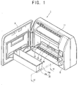
- FIG. 1 is a perspective view of a bread maker according to the present invention;
- FIG. 2 is a partially cut-away perspective view of a component compartment of FIG. 1;
- FIG. 3 is an exploded perspective view of a drum driving part of FIG. 2.
-
- Reference will now be made in detail to the embodiments of the present invention, examples of which are illustrated in the accompanying drawings, wherein like reference numerals refer to like elements throughout. The embodiments are described below in order to explain the present invention by referring to the figures.
- As shown in FIGS. 1 through 3, a bread maker of an embodiment of the present invention comprises: a
main body 1 divided into anoven compartment 10 and acomponent compartment 5, adoor 3 in the front of themain body 1 to open and close a front opening of theoven compartment 10; and an operation display panel (not shown) on a front side of themain body 1 to display an operation state of themain body 1. - In upper and lower parts inside of the
oven compartment 10 are placed upper andlower kneading drums oven compartment 10, abaking tray 15 containing kneaded materials therein is provided between the upper andlower kneading drums drum 11 and thebaking tray 15 is placed a pair of dough-blockingmembers 17 preventing the raw materials kneaded in the mixing bag from being moved toward the upper kneadingdrum 11. - The respective upper and
lower kneading drums main body 40 which is formed along a longitudinal direction thereof with a plurality of holding projections (not shown) to be inserted in holding holes (not shown) formed at end parts of the mixing bag; thedriving shaft part 41 which is extended outward from one end of the drummain body 40 and is rotatably supported on a wall of a first component compartment 21 (to be described later); and a supporting shaft part (not shown) which is extended outward from the other end of the drummain body 40 and is supported on the inner wall of theoven compartment 10 on the opposite side of the wall supporting the drivingshaft part 41 so as to be rotated in clockwise and counterclockwise directions. - The
baking tray 15 forms a box having a top opening by combining first andsecond trays - At upper and lower parts of the rear inner wall of the
oven compartment 10 and upper and lower parts of the inside wall of thedoor 3,baking heaters 19 are provided to heat the inside of theoven compartment 10. - The
component compartment 5 includes thefirst component compartment 21 beside theoven compartment 10 and asecond component compartment 23 behind theoven compartment 10. Inside thefirst component compartment 21 is placed a drum driving part (to be described later) rotating the upper andlower kneading drums - The drum driving part comprises: a
driving motor 26 to rotate thelower kneading drum 13; areduction gear 50 reducing the number of rotations of thedriving motor 26; aconnector 60 connecting anoutput shaft 55 of thereduction gear 50 and thedriving shaft part 41 of thelower kneading drum 13; upper andlower pulleys driving shaft parts 41 of the upper andlower kneading drums driving belt 80 which is connected to the pair ofpulleys lower kneading drums - A driving force generated by the
driving motor 26 is used to rotate thelower kneading drum 13 and transmitted to the drivingshaft part 41 of thelower kneading drum 13 connected to theoutput shaft 55 and theconnector 60 by means of thereduction gear 50 located in the lower part of thedriving motor 26. - The
reduction gear 50 comprises a worm gear set having aworm 53 and aworm wheel 54 in agear case 51 located under the drivingmotor 26 and accommodating the worm gear set. - The
worm 53 is connected to the end of theshaft 52 of thedriving motor 26 and theworm wheel 54 is connected to theoutput shaft 55, which in turn is connected to the drivingshaft part 41 of thelower kneading drum 13 by theconnector 60 and is engaged with theworm 53. - One side of the
connector 60 is connected to theoutput shaft 55 having theworm wheel 54 and the other side thereof is connected to thelower pulley 71 rotatably connected to thedriving shaft part 41 of thelower kneading drum 13. Theconnector 60 transmits the driving force from themotor 26 via thereduction gear 50 to thelower kneading drum 13. - Between the
connector 60 and thelower pulley 71 is placed an engager to make sure that the driving force speed-reduced of thereduction gear 50 is transmitted to the lower kneading drum, even if theconnector 60 and thelower pulley 71 are not assembled at the exact assembling positions. - The engager includes a plurality of
engaging projections 90 projected in a radial direction on an outer surface side of theconnector 60; and a plurality ofprojections accommodating grooves 91 provided at a corresponding position of thelower pulley 71 to accommodate theengaging projections 90 of theconnector 60. - The
engaging projections 90 are projected in a radial direction relative to the axis of theoutput shaft 55 on the outer surface of theconnector 60. As shown in FIG. 3, three equally spacedengaging projections 90 are projected on the outer surface of theconnector 60. - The
projections accommodating grooves 91 of thelower pulley 71 are distributed in a radial direction relative to the axis of theoutput shaft 55, matching the number ofengaging projections 90. - With this configuration, when the
driving motor 26 operates, the speed-reduced driving force generated by thedriving motor 26 is transmitted to thereduction gear 50. - The speed-reduced driving force is responsible for rotating the
lower kneading drum 13 as well as the upper kneadingdrum 11 connected to thelower kneading drum 13 by thetransmitting belt 80. - Regarding the assembly of the drum driving part which rotates the upper and
lower kneading drums connector 60 and thelower pulley 71 can be coupled with much ease only by accommodating theengaging projections 90 of theconnector 60 in theprojections accommodating grooves 91 of thelower pulley 71. This guarantees that the driving force generated by thedriving motor 26 is transmitted to thelower kneading drum 13, even if theconnector 60 and thelower pulley 71 are not assembled at the exact assembling positions. This saves time and effort assembling theconnector 60 and thelower pulley 71, and further the bread maker as a whole. - As described above, according to preferred embodiments of the present invention, the driving force of the driving motor can be smoothly transmitted to the lower kneading drum, thereby providing increased productivity by reducing time taken for assembling the bread maker.
- Although a few embodiments of the present invention have been shown and described, it will be appreciated by those skilled in the art that changes may be made in these embodiments without departing from the principles and spirit of the invention, the scope of which is defined in the appended claims and their equivalents.
- Attention is directed to all papers and documents which are filed concurrently with or previous to this specification in connection with this application and which are open to public inspection with this specification, and the contents of all such papers and documents are incorporated herein by reference.
- All of the features disclosed in this specification (including any accompanying claims, abstract and drawings), and/or all of the steps of any method or process so disclosed, may be combined in any combination, except combinations where at least some of such features and/or steps are mutually exclusive.
- Each feature disclosed in this specification (including any accompanying claims, abstract and drawings) may be replaced by alternative features serving the same, equivalent or similar purpose, unless expressly stated otherwise. Thus, unless expressly stated otherwise, each feature disclosed is one example only of a generic series of equivalent or similar features.
- The invention is not restricted to the details of the foregoing embodiment(s). The invention extends to any novel one, or any novel combination, of the features disclosed in this specification (including any accompanying claims, abstract and drawings), or to any novel one, or any novel combination, of the steps of any method or process so disclosed.
Claims (18)
- A bread maker comprising: a main body (1) divided into an oven compartment (10) and a component compartment (5);
upper and lower kneading (drums (11, 13) which are rotatably provided at upper and lower parts inside of the oven compartment (10) and wind opposite ends of a mixing bag filled with raw materials for bread; and a drum driving part placed in the component compartment (15) to rotate the upper and lower kneading drums (11, 13), the drum driving part comprising:a driving motor (26) generating a driving force to rotate the lower kneading drum (13);a reduction gear (50) which speed-reduces the driving force of the driving motor (26) and has an output shaft (55) thereof transmitting the speed-reduced driving force to the lower kneading drum (13);a connector (60) connecting the output shaft (55) and the lower kneading drum (13);upper and lower pulleys (70, 71) rotatably connected to the upper and lower kneading drums (11, 13), respectively;a driving belt (80) connected to the upper and lower pulleys (70, 71) to rotate the upper and lower kneading drums; andan engager connecting one side of the lower pulley (71) to the connector (60). - The bread maker according to claim 1, wherein the engager comprises a plurality of engaging projections (90) projected in a radial direction relative to an axis of the output shaft (55) on an outer surface of the connector; and
a plurality of projections accommodating grooves (91) formed in the lower pulley (71) to accommodate the plurality of engaging projections (90). - The bread maker according to claim 2, wherein three engaging projections (90) are uniformly distributed on the outer surface of the connector (60).
- The bread maker according to claim 2 or claim 3, wherein the reduction gear (50) includes a worm (53) connected to a shaft (55) of the driving motor (26) and a worm wheel (54) engaged with the worm (53), and a gear case (51) accommodating the worm (53) and the worm wheel (54).
- A driving mechanism, comprising:a driving motor (26) generating a driving force to rotate a first drum (13);a reduction gear (50) controlling the driving force of the driving motor (26) coupled to an output shaft transmitting the driving force to the first drum (13);a connector connecting the output shaft (55) and the first drum (13);a first pulley (71) rotatably connected to the first drum (13);a second pulley (70) rotatably connected to a second drum (11);a driving belt (80) connected to the first and second pulleys (70, 71) to rotate the first and second drums (13, 11); andan engager connecting one side of the first pulley to the connector (60).
- The drum driving mechanism according to claim 5, wherein the engager includes a plurality of engaging projections (90) projected in a radial direction relative to an axis of the output shaft (55) on an outer surface of the connector (60) and a plurality of projections accommodating grooves (91) formed in the first pulley (71) to accommodate the engaging projections (90).
- The drum driving mechanism according to claim 6, wherein at least one engaging projection (90) is located on the outer surface of the connector (60).
- The drum driving mechanism according to claim 6 or claim 7, wherein the reduction gear (50) further includes a worm (53) connected to a shaft (55) of the driving motor (26) and a worm wheel (54) engaged with the worm (53), and a gear case (51) accommodating the worm (53) and the worm wheel (54).
- A bread maker comprising an oven compartment (10) and a component compartment (5), wherein the component compartment (5) further comprises a drum driving mechanism, the drum driving mechanism including:a driving motor (26) rotating a first kneading drum (13);a reduction gear (50) controlling the number of rotations of the driving motor (26);a connector (60) connecting an output shaft (55) of the reduction gear (50) and connecting a first driving shaft (41) part of the first kneading drum (13);a second pulley (70) rotatably coupled to a second driving shaft part of a second kneading drum (11);a first pulley (71) rotatably coupled to the first driving shaft part (41) of the first kneading drum (13); anda driving belt (80) coupled to the first and second pulleys (71, 70) and rotating the first and second kneading drums (13, 11).
- The bread maker according to claim 9, wherein a driving force generated by the driving motor (26) is used to rotate the first kneading drum (13) and transmitted to the first driving shaft part (41) of the first kneading drum (13) connected to the output shaft (55) and the connector (60) by the reduction gear (50) located in a first part of the driving motor (26).
- The bread maker according to claim 9 or claim 10, wherein the reduction gear (50) further comprises a worm gear set having a worm (53) and a worm wheel (54) in a gear case (51) located under the driving motor (26).
- The bread maker according to claim 11, wherein the worm (53) is coupled to an end of a driving motor shaft, and the worm wheel is coupled to the output shaft (52) which is connected to the driving shaft part (41) of the first kneading drum (13) by the connector (60) and engaged with the worm (53).
- The bread maker according to claim 12, wherein one side of the connector (60) is connected to the output shaft (55) having the worm wheel (54) and a other side of the connector (60) is connected to the first pulley (71) rotatably connected to the driving shaft part (41) of the first kneading drum (13).
- The bread maker according to claim 13, wherein the connector (60) transmits the driving force from a motor (26) by the reduction gear (50) to the first kneading drum (13).
- The bread maker according to any one of claims 7-14, further comprising an engager provided between the connector (60) and the first pulley (13).
- The bread maker according to claim 15, wherein the engager further includes a plurality of engaging projections (90) projecting in a radial direction on an outer surface side of the connector (60), and a plurality of projections accommodating grooves (91) provided at corresponding positions of the first pulley (71) to accommodate the engaging projections (90) of the connector (60).
- The bread maker according to claim 16, wherein the plurality of engaging projections (90) are projected in a radial direction relative to an axis of the output shaft (55) on the outer surface of the connector (60).
- The bread maker according to claim 16 or claim 17, wherein the plurality of projections accommodating grooves (91) of the first pulley (71) are distributed in a radial direction relative to an axis of the output shaft (55) and match the engaging projections (90).
Applications Claiming Priority (2)
| Application Number | Priority Date | Filing Date | Title |
|---|---|---|---|
| KR2003029090 | 2003-05-07 | ||
| KR1020030029090A KR20040096218A (en) | 2003-05-07 | 2003-05-07 | Bake oven |
Publications (2)
| Publication Number | Publication Date |
|---|---|
| EP1474983A1 true EP1474983A1 (en) | 2004-11-10 |
| EP1474983B1 EP1474983B1 (en) | 2006-07-26 |
Family
ID=36848419
Family Applications (1)
| Application Number | Title | Priority Date | Filing Date |
|---|---|---|---|
| EP04250853A Expired - Lifetime EP1474983B1 (en) | 2003-05-07 | 2004-02-18 | Improvements in and relating to bread makers |
Country Status (6)
| Country | Link |
|---|---|
| US (1) | US20040221729A1 (en) |
| EP (1) | EP1474983B1 (en) |
| JP (1) | JP2004329903A (en) |
| KR (1) | KR20040096218A (en) |
| CN (1) | CN1275529C (en) |
| DE (1) | DE602004001624T2 (en) |
Families Citing this family (5)
| Publication number | Priority date | Publication date | Assignee | Title |
|---|---|---|---|---|
| CN102293593B (en) * | 2011-09-06 | 2014-09-17 | 浙江绍兴苏泊尔生活电器有限公司 | Bread maker |
| CN102283590B (en) * | 2011-09-06 | 2014-06-25 | 浙江绍兴苏泊尔生活电器有限公司 | Bread maker |
| CN102283593B (en) * | 2011-09-06 | 2014-06-25 | 浙江绍兴苏泊尔生活电器有限公司 | Bread maker |
| CN102293592B (en) * | 2011-09-06 | 2014-06-25 | 浙江绍兴苏泊尔生活电器有限公司 | Bread maker |
| CN102283589B (en) * | 2011-09-06 | 2014-07-16 | 浙江绍兴苏泊尔生活电器有限公司 | Bread maker |
Citations (4)
| Publication number | Priority date | Publication date | Assignee | Title |
|---|---|---|---|---|
| US3687251A (en) * | 1971-02-01 | 1972-08-29 | Minnesota Mining & Mfg | Torque transmitting device |
| US4590850A (en) * | 1983-12-27 | 1986-05-27 | Heden Team A.G. | Apparatus for automatically making of food products such as bread, cakes and the like |
| US5947009A (en) * | 1997-11-17 | 1999-09-07 | Heden-Team Ag | Automatic baking apparatus and mixbag thereof |
| EP1382251A1 (en) * | 2002-07-19 | 2004-01-21 | Samsung Electronics Co., Ltd. | Bread maker |
Family Cites Families (5)
| Publication number | Priority date | Publication date | Assignee | Title |
|---|---|---|---|---|
| KR100471071B1 (en) * | 2002-07-19 | 2005-03-10 | 삼성전자주식회사 | Automatic Baking Apparatus |
| KR100471073B1 (en) * | 2002-07-19 | 2005-03-10 | 삼성전자주식회사 | Oven for baking bread |
| KR100471072B1 (en) * | 2002-07-20 | 2005-03-10 | 삼성전자주식회사 | baking machine |
| KR100456587B1 (en) * | 2002-07-20 | 2004-11-10 | 삼성전자주식회사 | Baking machine |
| KR100473061B1 (en) * | 2002-09-14 | 2005-03-10 | 삼성전자주식회사 | Baking Apparatus |
-
2003
- 2003-05-07 KR KR1020030029090A patent/KR20040096218A/en not_active Withdrawn
-
2004
- 2004-02-18 EP EP04250853A patent/EP1474983B1/en not_active Expired - Lifetime
- 2004-02-18 DE DE602004001624T patent/DE602004001624T2/en not_active Expired - Fee Related
- 2004-02-23 CN CNB2004100059745A patent/CN1275529C/en not_active Expired - Fee Related
- 2004-03-19 US US10/803,913 patent/US20040221729A1/en not_active Abandoned
- 2004-03-30 JP JP2004101451A patent/JP2004329903A/en not_active Ceased
Patent Citations (4)
| Publication number | Priority date | Publication date | Assignee | Title |
|---|---|---|---|---|
| US3687251A (en) * | 1971-02-01 | 1972-08-29 | Minnesota Mining & Mfg | Torque transmitting device |
| US4590850A (en) * | 1983-12-27 | 1986-05-27 | Heden Team A.G. | Apparatus for automatically making of food products such as bread, cakes and the like |
| US5947009A (en) * | 1997-11-17 | 1999-09-07 | Heden-Team Ag | Automatic baking apparatus and mixbag thereof |
| EP1382251A1 (en) * | 2002-07-19 | 2004-01-21 | Samsung Electronics Co., Ltd. | Bread maker |
Also Published As
| Publication number | Publication date |
|---|---|
| US20040221729A1 (en) | 2004-11-11 |
| JP2004329903A (en) | 2004-11-25 |
| CN1550146A (en) | 2004-12-01 |
| EP1474983B1 (en) | 2006-07-26 |
| DE602004001624T2 (en) | 2007-07-19 |
| KR20040096218A (en) | 2004-11-16 |
| DE602004001624D1 (en) | 2006-09-07 |
| CN1275529C (en) | 2006-09-20 |
Similar Documents
| Publication | Publication Date | Title |
|---|---|---|
| EP1474983A1 (en) | Improvements in and relating to bread makers | |
| EP1382254A1 (en) | Improvements in and relating to bread makers | |
| US20050120888A1 (en) | Multi-function breadmaker | |
| CN215914342U (en) | Multifunctional automatic cake making machine | |
| EP1382253A1 (en) | Improvements in and relating to bread makers | |
| JP6028224B2 (en) | Automatic bread machine | |
| EP1382257B1 (en) | Improvements in and relating to bread makers | |
| EP1382251B1 (en) | Bread maker | |
| EP1474978A1 (en) | Bread maker | |
| EP1474979A1 (en) | Bread maker | |
| KR20020061409A (en) | Bake oven | |
| EP1474977A1 (en) | Bread maker and oven for bread maker | |
| EP1474980B1 (en) | Bread maker | |
| EP1475020B1 (en) | Bread maker | |
| EP1475019A1 (en) | Bread maker | |
| EP1474985A1 (en) | Bread maker | |
| JP6478944B2 (en) | Automatic bread machine | |
| JP2010184082A (en) | Automatic bread-making machine | |
| JP2018201681A (en) | Bread maker |
Legal Events
| Date | Code | Title | Description |
|---|---|---|---|
| PUAI | Public reference made under article 153(3) epc to a published international application that has entered the european phase |
Free format text: ORIGINAL CODE: 0009012 |
|
| 17P | Request for examination filed |
Effective date: 20040218 |
|
| AK | Designated contracting states |
Kind code of ref document: A1 Designated state(s): AT BE BG CH CY CZ DE DK EE ES FI FR GB GR HU IE IT LI LU MC NL PT RO SE SI SK TR |
|
| AX | Request for extension of the european patent |
Extension state: AL LT LV MK |
|
| 17Q | First examination report despatched |
Effective date: 20050117 |
|
| AKX | Designation fees paid |
Designated state(s): DE FR GB SE |
|
| GRAP | Despatch of communication of intention to grant a patent |
Free format text: ORIGINAL CODE: EPIDOSNIGR1 |
|
| GRAS | Grant fee paid |
Free format text: ORIGINAL CODE: EPIDOSNIGR3 |
|
| GRAA | (expected) grant |
Free format text: ORIGINAL CODE: 0009210 |
|
| AK | Designated contracting states |
Kind code of ref document: B1 Designated state(s): DE FR GB SE |
|
| REG | Reference to a national code |
Ref country code: GB Ref legal event code: FG4D |
|
| REF | Corresponds to: |
Ref document number: 602004001624 Country of ref document: DE Date of ref document: 20060907 Kind code of ref document: P |
|
| REG | Reference to a national code |
Ref country code: SE Ref legal event code: TRGR |
|
| ET | Fr: translation filed | ||
| PLBE | No opposition filed within time limit |
Free format text: ORIGINAL CODE: 0009261 |
|
| STAA | Information on the status of an ep patent application or granted ep patent |
Free format text: STATUS: NO OPPOSITION FILED WITHIN TIME LIMIT |
|
| 26N | No opposition filed |
Effective date: 20070427 |
|
| PGFP | Annual fee paid to national office [announced via postgrant information from national office to epo] |
Ref country code: GB Payment date: 20080213 Year of fee payment: 5 Ref country code: SE Payment date: 20080219 Year of fee payment: 5 |
|
| PGFP | Annual fee paid to national office [announced via postgrant information from national office to epo] |
Ref country code: FR Payment date: 20080208 Year of fee payment: 5 |
|
| PGFP | Annual fee paid to national office [announced via postgrant information from national office to epo] |
Ref country code: DE Payment date: 20090123 Year of fee payment: 6 |
|
| EUG | Se: european patent has lapsed | ||
| GBPC | Gb: european patent ceased through non-payment of renewal fee |
Effective date: 20090218 |
|
| REG | Reference to a national code |
Ref country code: FR Ref legal event code: ST Effective date: 20091030 |
|
| PG25 | Lapsed in a contracting state [announced via postgrant information from national office to epo] |
Ref country code: GB Free format text: LAPSE BECAUSE OF NON-PAYMENT OF DUE FEES Effective date: 20090218 Ref country code: FR Free format text: LAPSE BECAUSE OF NON-PAYMENT OF DUE FEES Effective date: 20090302 |
|
| PG25 | Lapsed in a contracting state [announced via postgrant information from national office to epo] |
Ref country code: DE Free format text: LAPSE BECAUSE OF NON-PAYMENT OF DUE FEES Effective date: 20100901 |
|
| PG25 | Lapsed in a contracting state [announced via postgrant information from national office to epo] |
Ref country code: SE Free format text: LAPSE BECAUSE OF NON-PAYMENT OF DUE FEES Effective date: 20090219 |