EP1382251A1 - Bread maker - Google Patents
Bread maker Download PDFInfo
- Publication number
- EP1382251A1 EP1382251A1 EP02258252A EP02258252A EP1382251A1 EP 1382251 A1 EP1382251 A1 EP 1382251A1 EP 02258252 A EP02258252 A EP 02258252A EP 02258252 A EP02258252 A EP 02258252A EP 1382251 A1 EP1382251 A1 EP 1382251A1
- Authority
- EP
- European Patent Office
- Prior art keywords
- drum
- kneading
- bag
- rotation shaft
- projections
- Prior art date
- Legal status (The legal status is an assumption and is not a legal conclusion. Google has not performed a legal analysis and makes no representation as to the accuracy of the status listed.)
- Granted
Links
- 235000008429 bread Nutrition 0.000 title claims abstract description 67
- 238000004898 kneading Methods 0.000 claims abstract description 180
- 238000004804 winding Methods 0.000 claims abstract description 15
- 239000004615 ingredient Substances 0.000 claims description 5
- 239000007787 solid Substances 0.000 claims description 3
- 238000000034 method Methods 0.000 description 8
- 239000002994 raw material Substances 0.000 description 4
- 230000003247 decreasing effect Effects 0.000 description 3
- 239000003638 chemical reducing agent Substances 0.000 description 2
- 238000010438 heat treatment Methods 0.000 description 2
- 238000010276 construction Methods 0.000 description 1
- 235000013312 flour Nutrition 0.000 description 1
- 238000007689 inspection Methods 0.000 description 1
- 239000000843 powder Substances 0.000 description 1
Images


Classifications
-
- A—HUMAN NECESSITIES
- A21—BAKING; EDIBLE DOUGHS
- A21B—BAKERS' OVENS; MACHINES OR EQUIPMENT FOR BAKING
- A21B7/00—Baking plants
- A21B7/005—Baking plants in combination with mixing or kneading devices
-
- A—HUMAN NECESSITIES
- A21—BAKING; EDIBLE DOUGHS
- A21B—BAKERS' OVENS; MACHINES OR EQUIPMENT FOR BAKING
- A21B1/00—Bakers' ovens
Definitions
- the present invention relates to bread makers, and more particularly, though not exclusively, to bread makers with an improved rotation structure between kneading drums.
- making bread is so complicated that it is difficult for an average person to manually make satisfactory bread at home. That is, making the bread is complicated because multiple steps are involved including mixing raw materials such as flour, sugar, baking powder, etc. to form a dough; kneading the dough; leavening the dough; baking the dough; and so on.
- a bread maker has been developed that allows a user to easily make bread.
- the bread maker automatically performs the foregoing multiple steps and provides finished bread to the user.
- a conventional bread maker includes a main body 100 divided into an oven compartment 110 and an electric component compartment 130, a door 300 in the front of the main body 100 to open and close the oven compartment 110, and a control panel (not shown) provided in the front of the electric component compartment 130 to allow a user to the bread maker.
- upper and lower kneading drums 150 and 170 are provided in parallel.
- the upper and lower kneading drums 150 and 170 have a plurality of projections 157 and 177 that engage a plurality of holes in upper and lower ends of a bag (not shown) filled with raw materials ingredients for preparing the bread.
- the projections 150 and 170 engage the holes in the bag to wind the bag in clockwise and counterclockwise directions.
- the upper and lower kneading drums 150 and 170 are rotatably connected to upper and lower opposite inner-walls of the main body 100 using respective bearings 111.
- a baking tray 113 in which the dough is contained for baking.
- On the inside walls of the main body 100 and the door 300 are respective heaters 115 for heating the baking tray 113.
- a drum driving part 133 including a motor 133b incorporated with a gear reducer 133a to rotate the lower kneading drum 170 in clockwise and counterclockwise directions, and a belt 135 connecting the upper and lower kneading drums 150 and 170 to transmit a rotary movement from the lower kneading drum 170 to the upper kneading drum 150.
- the drum driving part 133 and the lower kneading drum 170 are connected by a coupler 131.
- the process of setting up the bag on the upper and lower kneading drums 150 and 170 is performed as follows.
- the holes provided in the upper end of the bag engage with the projections 157 of the upper kneading drum 150, and then the bag is wound on the upper kneading drum 150 by rotating the drum driving part 133. At this time, the bag is wound only enough to place the lower end of the bag at the projections 177 of the lower kneading drum 170. Then, the holes provided in the lower end of the bag engage with the projections 177 of the lower kneading drum 170, thereby completing the setting up process.
- the projections 157 of the upper kneading drum 150 are rotated depending upon the rotary movement of the projections 177 of the lower kneading drum 170.
- the holes provided in the lower end of the bag deviate from the projections 177 of the lower kneading drum 170 because, for example, the bag is not wound sufficiently to place the lower end of the bag at the projections 177 of the lower kneading drum 170, the user must restart the setting up process.
- the drum driving part 133 must be operated to remove the bag from the bread maker, which increases electric power consumption.
- a bread maker including an oven compartment, parallel kneading drums inside the oven compartment that alternate between winding and unwinding rotations, and a drum driving part rotating the kneading drums; each kneading drum includes a rotation shaft rotating according to the drum driving part; a drum member disposed concentrically along an axis of the rotation shaft; and a clutch between the rotation shaft and the drum member, transmitting a rotary movement from the rotation shaft to the drum member in one direction and allowing the drum member to freewheel in the other direction.
- the drum member is a cylinder in which the rotation shaft is accommodated.
- a bread maker including an oven compartment, parallel kneading drums inside the oven compartment that alternate between winding and unwinding rotations, and a drum driving part rotating the kneading drums; each kneading drum includes a solid cylindrical drum member; a rotation shaft accommodated by the drum member and rotated by the drum driving part; and a clutch connecting the rotation shaft and the drum member, the clutch transmitting a rotary movement from the rotation shaft to the drum member in one direction and allowing the drum member to freewheel in the other direction.
- a kneading drum apparatus for a bread maker including an upper kneading drum and a lower kneading drum; a rotation shaft in the upper kneading drum and the lower kneading drum; a hollow, cylindrical drum member disposed concentrically around each rotation shaft; a drum driving part rotating one of the upper kneading drum and the lower kneading drum; a belt connecting the rotation shafts of the upper kneading drum and the lower kneading drum and transmitting a rotary movement from the kneading drum rotated by the drum driving part to the other kneading drum; and a clutch connecting the rotation shaft to the drum member in the upper kneading drum and the lower kneading drum; the clutch transmits the rotary movement from the rotation shaft to the drum member in one direction and allows the drum member to free
- a bread maker according to a first embodiment of the present invention includes a main body 1 divided into an oven compartment 10 and an electric component compartment 30, a door 3 in the front of the main body 1 to open and close the oven compartment 10, and a control panel (not shown) in the front of the electric component compartment 30 to allow a user to control the bread maker.
- upper and lower kneading drums 50 and 70 are provided in parallel and engage a bag (not shown) filled with raw materials for preparing the bread by winding the bag in clockwise and counterclockwise directions.
- the upper and lower kneading drums 50 and 70 are rotatably connected to upper and lower opposite inner-walls of the main body 1 using respective bearings 11 ( Figure 4).
- the upper and lower kneading drums 50 and 70 are rotated by a drum driving part 33 (described below), which winds the bag on and off the upper and lower kneading drums 50 and 70, thereby kneading the dough in the bag.
- a baking tray 13 in which the dough is contained for baking.
- On the inside walls of the main body 1 and the door 3 are respective heaters 15 for heating the baking tray 13.
- the electric component compartment 30 Beside the oven compartment 10 is the electric component compartment 30.
- the drum driving part 33 Inside the electric component compartment 30 is the drum driving part 33, including a motor 33b incorporated with a gear reducer 33a to rotate the lower kneading drum 70 in clockwise and counterclockwise directions.
- the drum driving part 33 is connected to one side of the lower kneading drum 70 by a coupler 31.
- the upper and lower kneading drums 50 and 70 both include respective rotation shafts 51 and 71 that are rotated by the drum driving part 33, respective drum members 53 and 73 that lay concentrically along the axis of the respective rotation shafts 51 and 71, and respective clutches 55 and 75 that are placed between the rotation shafts 51 and 71 and the drum members 53 and 73.
- the clutches 55 and 75 connect the rotation shafts 51 and 71 with the drum members 53 and 73 when the bag is wound on the upper and lower kneading drums 50 and 70, and disconnect the rotation shafts 51 and 71 from the drum members 53 and 73 when the bag is wound off the upper and lower kneading drums 50 and 70.
- the rotation shaft 71 of the lower kneading drum 70 is connected to the drum driving part 33 of the electric component compartment 30 by the coupler 31 and is rotated by the drum driving part 33, alternating between a winding direction and an unwinding direction. Further, the rotation shaft 71 of the lower kneading drum 70 is connected to the rotation shaft 51 of the upper kneading drum 50 by a belt 35, so that a rotational force (or rotary movement) is transmitted from the lower rotation shaft 71 to the upper rotation shaft 51.
- the upper and lower drum members 53 and 73 are hollow cylinders and respectively accommodate the upper and lower rotation shafts 51 and 71, forming an outer portion of the upper and lower kneading drums 50 and 70.
- the upper and lower drum members 53 and 73 have a plurality of respective projections 57 and 77 at regular intervals, and the plurality of projections 57 and 77 engage the holes of the upper and lower ends of the bag.
- the clutches 55 and 75 are placed between the rotation shafts 51 and 71 and the drum members 53 and 73, and allow the drum members 53 and 73 to freewheel relative to the rotation shafts 51 and 71 in one direction only. Hence, the clutches 55 and 75 allow the drum members 53 and 73 to freewheel relative to the rotation shafts 51 and 71 when the bag is wound on the drum members 53 and 73, but prevent the drum members 53 and 73 from freewheeling relative to the rotation shafts 51 and 71 when the bag is wound off the drum members 53 and 73.
- the processes of setting up, kneading, and removing the bag are performed as follows.
- the holes in the upper end of the bag filled with raw materials for the bread engage the projections 57 in the drum member 53 of the upper kneading drum 50. Thereafter, the upper kneading drum 50 rotates so that the bag is wound on the upper kneading drum 50.
- the drum member 53 of the upper kneading drum 50 may be manually rotated relative to the rotation shaft 51 without operating the drum driving part 33, thereby decreasing electric power consumption.
- the holes provided in the lower end of the bag engage the projections 77 provided in the drum member 73 of the lower kneading drum 70.
- the holes of the bag may engage the projections 77 of the lower kneading drum 70 by properly rotating the drum member 73 in the winding direction.
- the drum driving part 33 rotates the upper and lower rotation shafts 51 and 71.
- the upper rotation shaft 51 is rotated in the unwinding direction, and vice versa.
- the upper drum member 53a of the upper kneading drum 50a is a solid cylinder, in contrast to the drum members 53 and 73 according to the first embodiment of the present invention, in which the drum members 53 and 73 are hollow cylinders through which the long rotation shafts 51 and 71 pass, respectively.
- short rotation shafts 51a are provided on opposite inner walls of the upper and lower parts of the oven compartment 10, respectively.
- the drum member 53a and the rotation shaft 51a are connected by a clutch 55a placed between the drum member 53a and the rotation shaft 51a.
- the clutches 55, 75, and 55a are provided at opposite ends of the upper and lower kneading drums 50, 70, and 50a.
- the clutches 55, 75, and 55a may be provided at one end of the upper and lower kneading drums 50, 70, and 50a, to which a rotary movement of the drum driving part 33 is first transmitted.
- the upper and lower kneading drums 50, 70, and 50a include the upper and lower rotation shafts 51, 71, and 51a that rotate according to the drum driving part 33, and the upper and lower drum members 53, 73, and 53a freewheel relative to the upper and lower rotation shafts 51, 71, and 51a in one direction only, so that the bag can be easily set up and removed from the upper and lower kneading drums 50, 70, and 50a.
- the bag may be manually set up and removed from the upper and lower kneading drums 50, 70, and 50a, thereby decreasing electric power consumption.
- preferred embodiments of the present invention provide a bread maker in which upper and lower drum members 50, 70, and 50a may freewheel, so that a bag can be easily set up and removed.
- preferred embodiments of the present invention provides a bread maker in which a bag may be manually set up and removed, thereby decreasing electric power consumption.
Abstract
Description
- The present invention relates to bread makers, and more particularly, though not exclusively, to bread makers with an improved rotation structure between kneading drums.
- Generally, making bread is so complicated that it is difficult for an average person to manually make satisfactory bread at home. That is, making the bread is complicated because multiple steps are involved including mixing raw materials such as flour, sugar, baking powder, etc. to form a dough; kneading the dough; leavening the dough; baking the dough; and so on.
- Therefore, a bread maker has been developed that allows a user to easily make bread. The bread maker automatically performs the foregoing multiple steps and provides finished bread to the user.
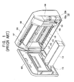
- As shown in Figures 1 and 2, a conventional bread maker includes a
main body 100 divided into anoven compartment 110 and anelectric component compartment 130, adoor 300 in the front of themain body 100 to open and close theoven compartment 110, and a control panel (not shown) provided in the front of theelectric component compartment 130 to allow a user to the bread maker. - Inside the
oven compartment 110, upper andlower kneading drums kneading drums projections projections lower kneading drums main body 100 usingrespective bearings 111. - Between the upper and
lower kneading drums baking tray 113 in which the dough is contained for baking. On the inside walls of themain body 100 and thedoor 300 arerespective heaters 115 for heating thebaking tray 113. - Beside the
oven compartment 110 is theelectric component compartment 130. Inside theelectric component compartment 130 are adrum driving part 133, including amotor 133b incorporated with agear reducer 133a to rotate thelower kneading drum 170 in clockwise and counterclockwise directions, and abelt 135 connecting the upper andlower kneading drums lower kneading drum 170 to theupper kneading drum 150. Thedrum driving part 133 and thelower kneading drum 170 are connected by acoupler 131. - With the conventional configuration, the process of setting up the bag on the upper and
lower kneading drums - First, the holes provided in the upper end of the bag engage with the
projections 157 of the upper kneadingdrum 150, and then the bag is wound on the upper kneadingdrum 150 by rotating thedrum driving part 133. At this time, the bag is wound only enough to place the lower end of the bag at theprojections 177 of thelower kneading drum 170. Then, the holes provided in the lower end of the bag engage with theprojections 177 of thelower kneading drum 170, thereby completing the setting up process. - However, in the conventional bread maker, because the upper and lower
kneading drums drum driving part 133, theprojections 157 of theupper kneading drum 150 are rotated depending upon the rotary movement of theprojections 177 of thelower kneading drum 170. Hence, if the holes provided in the lower end of the bag deviate from theprojections 177 of thelower kneading drum 170 because, for example, the bag is not wound sufficiently to place the lower end of the bag at theprojections 177 of thelower kneading drum 170, the user must restart the setting up process. - Further, in the conventional bread maker, the
drum driving part 133 must be operated to remove the bag from the bread maker, which increases electric power consumption. - It is an aim of preferred embodiments of the present invention to provide a bread maker in which a mixing bag may be easily installed and removed.
- Additional advantages of preferred embodiments of the invention will be set forth in part in the description that followed, and, in part, will be obvious from the description, or may be learned by practice of the invention.
- According to an aspect of the present invention, there is provided a bread maker including an oven compartment, parallel kneading drums inside the oven compartment that alternate between winding and unwinding rotations, and a drum driving part rotating the kneading drums; each kneading drum includes a rotation shaft rotating according to the drum driving part; a drum member disposed concentrically along an axis of the rotation shaft; and a clutch between the rotation shaft and the drum member, transmitting a rotary movement from the rotation shaft to the drum member in one direction and allowing the drum member to freewheel in the other direction.
- Suitably, the drum member is a cylinder in which the rotation shaft is accommodated.
- According to another aspect of the present invention, there is provided a bread maker including an oven compartment, parallel kneading drums inside the oven compartment that alternate between winding and unwinding rotations, and a drum driving part rotating the kneading drums; each kneading drum includes a solid cylindrical drum member; a rotation shaft accommodated by the drum member and rotated by the drum driving part; and a clutch connecting the rotation shaft and the drum member, the clutch transmitting a rotary movement from the rotation shaft to the drum member in one direction and allowing the drum member to freewheel in the other direction.
- According to another aspect of the present invention, there is provided a kneading drum apparatus for a bread maker, including an upper kneading drum and a lower kneading drum; a rotation shaft in the upper kneading drum and the lower kneading drum; a hollow, cylindrical drum member disposed concentrically around each rotation shaft; a drum driving part rotating one of the upper kneading drum and the lower kneading drum; a belt connecting the rotation shafts of the upper kneading drum and the lower kneading drum and transmitting a rotary movement from the kneading drum rotated by the drum driving part to the other kneading drum; and a clutch connecting the rotation shaft to the drum member in the upper kneading drum and the lower kneading drum; the clutch transmits the rotary movement from the rotation shaft to the drum member in one direction and allows the drum member to freewheel in the other direction.
- Further features of the present invention are set out in the appended claims.
- These together with other aspects and advantages which will be subsequently apparent, reside in the details of construction and operation as more fully hereinafter described and claimed, reference being had to the accompanying drawings forming a part thereof, wherein like numerals refer to like parts throughout.
- The present invention will become apparent and more readily appreciated from the following description of the embodiments thereof, by way of example only, taken in conjunction with the accompany drawings, of which:
- Figure 1 is a perspective view of a conventional bread maker;
- Figure 2 is a front sectional view schematically illustrating the conventional bread maker of Figure 1;
- Figure 3 is a perspective view of a bread maker according to a first embodiment of the present invention;
- Figure 4 is a front sectional view schematically illustrating the bread maker of Figure 3;
- Figure 5 is an enlarged sectional view partially illustrating the bread maker of Figure 4; and
- Figure 6 is an enlarged sectional view partially illustrating a bread maker according to a second embodiment of the present invention.
-
- Hereinafter, embodiments of the present invention will be described in detail with reference to the attached drawings, wherein the like reference numerals refer to the like elements throughout. The present invention may, however, be embodied in many different forms and should not be construed as being limited to the embodiments set forth herein; rather, these embodiments are provided so that the present disclosure will be thorough and complete, and will fully convey the concept of the invention to those skilled in the art.
- As shown in Figure 3, a bread maker according to a first embodiment of the present invention includes a main body 1 divided into an
oven compartment 10 and anelectric component compartment 30, adoor 3 in the front of the main body 1 to open and close theoven compartment 10, and a control panel (not shown) in the front of theelectric component compartment 30 to allow a user to control the bread maker. - Inside the
oven compartment 10, upper andlower kneading drums lower kneading drums drums drums - Between the upper and
lower kneading drums baking tray 13 in which the dough is contained for baking. On the inside walls of the main body 1 and thedoor 3 arerespective heaters 15 for heating thebaking tray 13. - Beside the
oven compartment 10 is theelectric component compartment 30. Inside theelectric component compartment 30 is thedrum driving part 33, including amotor 33b incorporated with agear reducer 33a to rotate thelower kneading drum 70 in clockwise and counterclockwise directions. Thedrum driving part 33 is connected to one side of thelower kneading drum 70 by acoupler 31. - Referring to Figures 4 and 5, the upper and lower
kneading drums respective rotation shafts drum driving part 33,respective drum members respective rotation shafts respective clutches rotation shafts drum members clutches rotation shafts drum members drums rotation shafts drum members lower kneading drums - The
rotation shaft 71 of thelower kneading drum 70 is connected to thedrum driving part 33 of theelectric component compartment 30 by thecoupler 31 and is rotated by thedrum driving part 33, alternating between a winding direction and an unwinding direction. Further, therotation shaft 71 of thelower kneading drum 70 is connected to therotation shaft 51 of theupper kneading drum 50 by abelt 35, so that a rotational force (or rotary movement) is transmitted from thelower rotation shaft 71 to theupper rotation shaft 51. - The upper and
lower drum members lower rotation shafts lower kneading drums lower drum members respective projections 57 and 77 at regular intervals, and the plurality ofprojections 57 and 77 engage the holes of the upper and lower ends of the bag. - The
clutches rotation shafts drum members drum members rotation shafts clutches drum members rotation shafts drum members drum members rotation shafts drum members - In the bread maker according to preferred embodiments of the present invention, the processes of setting up, kneading, and removing the bag are performed as follows.
- First, the holes in the upper end of the bag filled with raw materials for the bread engage the
projections 57 in thedrum member 53 of theupper kneading drum 50. Thereafter, the upper kneadingdrum 50 rotates so that the bag is wound on the upper kneadingdrum 50. Thedrum member 53 of the upper kneadingdrum 50 may be manually rotated relative to therotation shaft 51 without operating thedrum driving part 33, thereby decreasing electric power consumption. - When the bag is wound enough to place the lower end of the bag at the projections 77 of the
lower kneading drum 70, the holes provided in the lower end of the bag engage the projections 77 provided in thedrum member 73 of thelower kneading drum 70. At this time, even if the holes provided in the lower end of the bag deviate from the projections 77 of thelower kneading drum 70, the holes of the bag may engage the projections 77 of thelower kneading drum 70 by properly rotating thedrum member 73 in the winding direction. - After the bag is completely set up, the
drum driving part 33 rotates the upper andlower rotation shafts lower rotation shaft 71 is rotated in the winding direction, theupper rotation shaft 51 is rotated in the unwinding direction, and vice versa. - That is, when the
lower rotation shaft 71 rotates in the winding direction, thelower drum member 73 rotates with thelower rotation shaft 71, with the lower end of the bag being wound thereon. Simultaneously, when theupper rotation shaft 51 rotates in the unwinding direction by cooperating with thelower rotation shaft 71, theupper drum member 53 rotates in the unwinding direction independently of theupper rotation shaft 51 because thelower drum member 73 pulls the bag down while rotating. On the other hand, when theupper rotation shaft 51 rotates in the winding direction, the upper andlower drum members - According to a second embodiment of the present invention, as shown in Figure 6, the
upper drum member 53a of theupper kneading drum 50a, as well as the lower drum member of the lower kneading drum (not shown), is a solid cylinder, in contrast to thedrum members drum members long rotation shafts short rotation shafts 51a are provided on opposite inner walls of the upper and lower parts of theoven compartment 10, respectively. Further, thedrum member 53a and therotation shaft 51a are connected by a clutch 55a placed between thedrum member 53a and therotation shaft 51a. - In the foregoing embodiments, the
clutches clutches drum driving part 33 is first transmitted. As described above, the upper and lower kneading drums 50, 70, and 50a include the upper andlower rotation shafts drum driving part 33, and the upper andlower drum members lower rotation shafts - Further, the bag may be manually set up and removed from the upper and lower kneading drums 50, 70, and 50a, thereby decreasing electric power consumption.
- As described above, preferred embodiments of the present invention provide a bread maker in which upper and
lower drum members - Further, preferred embodiments of the present invention provides a bread maker in which a bag may be manually set up and removed, thereby decreasing electric power consumption.
- Although a few embodiments of the present invention have been shown and described, it will be appreciated by those skilled in the art that changes may be made in these embodiments without departing from the principles and spirit of the invention, the scope of which is defined in the appended claims and their equivalents.
- The reader's attention is directed to all papers and documents which are filed concurrently with or previous to this specification in connection with this application and which are open to public inspection with this specification, and the contents of all such papers and documents are incorporated herein by reference.
- All of the features disclosed in this specification (including any accompanying claims, abstract and drawings), and/or all of the steps of any method or process so disclosed, may be combined in any combination, except combinations where at least some of such features and/or steps are mutually exclusive.
- Each feature disclosed in this specification (including any accompanying claims, abstract and drawings), may'be replaced by alternative features serving the same, equivalent or similar purpose, unless expressly stated otherwise. Thus, unless expressly stated otherwise, each feature disclosed is one example only of a generic series of equivalent or similar features.
- The invention is not restricted to the details of the foregoing embodiment(s). The invention extends to any novel one, or any novel combination, of the features disclosed in this specification (including any accompanying claims, abstract and drawings), or to any novel one, or any novel combination, of the steps of any method or process so disclosed.
Claims (30)
- A bread maker comprising an oven compartment (10), parallel kneading drums (50, 70, 50a) inside the oven compartment (10) that alternate between winding and unwinding rotations, and a drum driving part (33) rotating the kneading drums (50, 70, 50a), each kneading drum comprising:a rotation shaft (51, 71, 51a) rotating according to the drum driving part (33);a drum member (53, 73, 53a) disposed concentrically along an axis of the rotation shaft (51, 71, 51a); anda clutch (55, 75, 55a) between the rotation shaft (51, 71, 51a) and the drum member (53, 73, 53a), transmitting a rotary movement from the rotation shaft (51, 71, 51a) to the drum member (53, 73, 53a) in one direction and allowing the drum member (53, 73, 53a) to freewheel in the other direction.
- The bread maker according to claim 1, wherein the drum member (53, 73) is a cylinder in which the rotation shaft (51, 71) is accommodated.
- The bread maker according to claim 1 or claim 2, wherein the kneading drums (50, 70, 50a) are rotatably connected to upper and lower opposite inner-walls of a main body (1) using respective bearings.
- The bread maker according to any preceding claim, further comprising a belt connecting the rotation shafts (51, 71, 51a) of the kneading drums (50, 70, 50a) to transmit a rotary movement between the kneading drums (50, 70, 50a).
- The bread maker of claim 1, wherein the drum members (53, 73) are hollow cylinders and the rotation shafts (51, 71) are longer than the drum members (53, 73) and pass through the respective hollow drum members (53, 73), the drum members (53, 73) forming an outer portion of the respective kneading drums (50, 70).
- The bread maker according to any preceding claim, wherein the clutches (55, 75, 55a) are located at opposite ends of the kneading drums (50, 70, 50a).
- The bread maker according to claim 1, wherein the clutches are located at an end of the kneading drums to which the rotary movement is applied.
- The bread maker according to any preceding claim, wherein the drum members (53, 73, 53a) have a plurality of projections (57, 77) and a bag filled with bread dough is attached to the projections (57, 77) and wound on and off the kneading drums (50, 70, 50a) using the driving part (33), thereby kneading the dough in the bag.
- The bread maker according to claim 8, wherein, for each kneading drum (50, 70, 50a), the clutch (55, 75, 55a) connects the rotation shaft (51, 71, 51a) with the drum member (53. 73. 53a) when the bag is wound on the kneading drum (50, 70, 50a), and disconnects the rotation shaft (51, 71, 51a) from the drum member (53, 73, 53a) when the bag is wound off the kneading drum (50, 70, 50a).
- The bread maker according to claim 8 or claim 9, wherein, for each kneading drum (50, 70, 50a) , the clutch (55, 75, 55a) allows the drum member (53, 73, 53a) to freewheel relative to the rotation shaft (51, 71, 51a) when the bag is wound on the drum member (53, 73, 53a), but prevents the drum member (53, 73, 53a) from freewheeling relative to the rotation shaft (51, 71, 51a) when the bag is wound off the drum member (53, 73, 53a).
- The bread maker according to any one of claims 8-10, wherein the kneading drums (50, 70, 50a) include an upper kneading drum (50, 50a) and a lower kneading drum (70) and holes in an upper end of the bag engage the projections (57) in the drum member (53, 53a) of the upper kneading drum (50, 50a), and the upper kneading drum (50, 50a) is rotated sufficiently to wind the bag on the upper kneading drum (50, 50a) and position holes in a lower end of the bag at the projections (57) of the drum member (73) of the lower kneading drum (70).
- The bread maker according to claim 11, wherein the drum driving part (33) alternately rotates the rotation shafts (51, 71, 51a), with the rotation shaft (71) of the lower kneading drum (73)rotating in a winding direction and the rotation shaft (51, 51a) of the upper kneading drum (53, 53a) rotating in an unwinding direction, and vice versa.
- The bread maker according to claim 11 or claim 12, wherein when the rotation shaft (71) of the lower kneading drum (70) rotates in a winding direction, the respective drum member (73) rotates with the rotation shaft (71) of the lower kneading drum to wind the lower end of the bag on the lower kneading drum (70), while, simultaneously, the rotation shaft (51, 51a) of the upper kneading drum (50, 50a) rotates in an unwinding direction and the respective drum member (53, 53a) rotates independently of the rotation shaft of the upper kneading drum (50, 50a) as the drum member (73) of the lower kneading drum (70) pulls down the bag, and vice versa.
- The bread maker according to any one of claims 11-13, wherein the drum members (53, 73, 53a) of the kneading drums (50, 70, 50a) are manually rotated relative to the respective rotation shafts (51, 71, 51a) without operating the drum driving part (33) to decrease electric power consumption.
- A bread maker comprising an oven compartment (10), parallel kneading drums (50a, 70) inside the oven compartment (10) that alternate between winding and unwinding rotations, and a drum driving part (33) rotating the kneading drums (50a, 70), each kneading drum comprising:a solid cylindrical drum member (53a);a rotation shaft (51a) accommodated by the drum member (53a) and rotated by the drum driving part (33); anda clutch (55a) connecting the rotation shaft (51a) and the drum member (53a), transmitting a rotary movement from the rotation shaft (51a) to the drum member (53a) in one direction and allowing the drum member (53a) to freewheel in the other direction.
- The bread maker according to claim 15, wherein the kneading drums (50a, 70) are rotatably connected to upper and lower opposite inner-walls of a main body using respective bearings.
- The bread maker according to claim 15 or claim 16, further comprising a belt connecting the rotation shafts (51a, 71) of the kneading drums to transmit a rotary movement between the kneading drums (50a, 70).
- The bread maker of any one of claims 15-17, wherein the drum members (53a, 73) are longer than the rotation shafts (51a, 71) and the rotation shafts (51a, 71) are incorporated into the drum members (53a, 73) at ends of the drum members (53a, 73) and connected to opposite inner walls of upper and lower parts of the oven compartment (10).
- The bread maker according to any one of claims 15-18, wherein:the drum members (53a, 73) have a plurality of projections (57, 77) and a bag filled with bread dough is attached to the projections (57, 77) and wound on and off the kneading drums (50a, 70) using the driving part (33), thereby kneading the dough in the bag; andfor each kneading drum (50a, 70), the clutch (55a, 75) connects the rotation shaft (51a, 71) with the drum member (53a, 73) when the bag is wound on the kneading drum (50a, 70), and disconnects the rotation shaft (51a, 70) from the drum member when the bag is wound off the kneading drum (50a, 70).
- The bread maker according to any one of claims 15-18, wherein:the drum members (53a, 73) have a plurality of projections (57, 77) and a bag filled with bread dough is attached to the projections (57, 77) and wound on and off the kneading drums (50a, 70) using the driving part (33), thereby kneading the dough in the bag; andfor each kneading drum (50a, 70), the clutch (55, 75) allows the drum member (53a, 73) to freewheel relative to the rotation shaft (51a, 71) when the bag is wound on the drum member (53a, 73), but prevents the drum member (53a, 73) from freewheeling relative to the rotation shaft (51a, 71) when the bag is wound off the drum member (53a, 73).
- The bread maker according to any one of claims 15-18, wherein:the drum members (53a, 73) have a plurality of projections (57, 77) and a bag filled with bread dough is attached to the projections (57, 77) and wound on and off the kneading drums (50a, 70) using the driving part (33), thereby kneading the dough in the bag;the kneading drums (50a, 70) include an upper kneading drum (50a) and a lower kneading drum (70) and holes in an upper end of the bag engage the projections (57) in the drum member of the upper kneading drum (50a), and the upper kneading drum (50a) is rotated sufficiently to wind the bag on the upper kneading drum (50a) and position holes in a lower end of the bag at the projections (57) of the drum member (73) of the lower kneading drum (70); andthe drum driving part (33) alternately rotates the rotation shafts (51a, 71), with the rotation shaft (71) of the lower kneading drum (70) rotating in a winding direction and the rotation shaft (51a) of the upper kneading drum (50a) rotating in an unwinding direction, and vice versa.
- The bread maker according to any one of claims 15-18, wherein:the drum members (53, 73a) have a plurality of projections (57, 77) and a bag filled with bread dough is attached to the projections (57, 77) and wound on and off the kneading drums (50a, 70) using the driving part (33), thereby kneading the dough in the bag;the kneading drums (50a, 70) include an upper kneading drum (50a) and a lower kneading drum (70) and holes in an upper end of the bag engage the projections (57, 77) in the drum member (53a) of the upper kneading drum (50a), and the upper kneading drum (50a) is rotated sufficiently to wind the bag on the upper kneading drum (50a) and position holes in a lower end of the bag at the projections (77) of the drum member (73) of the lower kneading drum (70); andthe drum members (53a, 73) of the kneading drums (50a, 70) are manually rotated relative to the respective rotation shafts (51a, 71) without operating the drum driving part (33) to decrease electric power consumption.
- A kneading drum apparatus for a bread maker, comprising:an upper kneading drum (50, 50a) and a lower kneading drum (70);a rotation shaft (51, 71, 51a) in the upper kneading drum (50, 50a) and the lower kneading drum (70);a drum member (53, 73, 53a) disposed concentrically around each rotation shaft (51, 71, 51a);a drum driving part (33) rotating one of the upper kneading drum (50, 50a) and the lower kneading drum (70);a belt (35) connecting the rotation shafts (51, 71, 51a) of the upper kneading drum (50, 50a) and the lower kneading drum (70) and transmitting a rotary movement from the kneading drum rotated by the drum driving part (33) to the other kneading drum; anda clutch (55, 75, 55a) connecting the rotation shaft (51, 71, 51a) to the drum member (53, 73, 53a) in the upper kneading drum (50, 50a) and the lower kneading drum (70), the clutch (55, 75, 55a) transmitting the rotary movement from the rotation shaft (51, 71, 51a) to the drum member (53, 73, 53a) in one direction and allowing the drum member (53, 73, 53a) to freewheel in the other direction.
- The apparatus according to claim 23, wherein the upper kneading drum (50, 50a) and the lower kneading drum (70) are rotatably connected to upper and lower opposite inner-walls of a main body of the bread maker using respective bearings.
- The apparatus according to claim 23, wherein each drum member (53, 73, 53a) is a hollow cylinder accommodating a respective rotation shaft and forming an outer portion of the upper kneading drum (50) and the lower kneading drum (70).
- The apparatus of claim 23, wherein the rotation shafts (51, 71, 51a) are longer than the drum members (53, 73, 53a) and the rotation shafts pass through the hollow drum members (53, 73, 53a).
- The apparatus according to any one of claims 23-26, wherein:the drum members (53, 73, 53a) have a plurality of projections (57, 77) and a bag filled with ingredients for bread is attached to the projections (57, 77) and wound on and off the upper kneading drum (53, 53a) and the lower kneading drum (73); andthe clutch (55, 75, 55a) connects the rotation shaft (51, 71, 51a) with the drum member (53, 73, 53a) when the bag is wound on the corresponding upper kneading drum (50, 50a) or the lower kneading drum (70), and disconnects the rotation shaft (51, 71, 51a) from the drum member (53, 73, 53a) when the bag is wound off the corresponding upper kneading drum (50, 50a) or the lower kneading drum (70).
- The apparatus according to claim 23, wherein:the drum members (53, 73, 53a) have a plurality of projections (57, 77) and a bag filled with ingredients for bread is attached to the projections (57, 77) and wound on and off the upper kneading drum (50, 50a) and the lower kneading drum (70); andthe clutches (55, 75, 55a) allow the respective drum members (53, 73, 53a) to freewheel relative to the respective rotation shafts (51, 71, 51a) when the bag is wound on the drum members (53, 73, 53a), but prevents the respective drum members (53, 73, 53a) from freewheeling relative to the rotation shafts (51, 71, 51a) when the bag is wound off the respective drum members (53, 73, 53a).
- The apparatus according to claim 23, wherein:the drum members (53, 73, 53a) have a plurality of projections (57, 77) and a bag filled with ingredients for bread is attached to the projections (57, 77) and wound on and off the upper kneading drum (50, 50a) and the lower kneading drum (70);holes in an upper end of the bag engage the projections (57, 77) in the drum member (53, 53a) of the upper kneading drum (50, 50a), and the upper kneading drum (53, 53a) is sufficiently rotated to wind the bag on the upper kneading drum (53, 53a) and position holes in a lower end of the bag at the projections (57, 77) of the drum member (73) of the lower kneading drum (70); andthe drum driving part (33) alternately rotates the rotation shafts (51, 71, 51a), with the rotation shaft (71) of the lower kneading drum (73) rotating in a winding direction and the rotation shaft (51, 51a) of the upper kneading drum (53, 53a) rotating in an unwinding direction, and vice versa.
- The apparatus according to claim 23, wherein:the drum members (53, 73, 53a) have a plurality of projections (57, 77) and a bag filled with ingredients for bread is attached to the projections (57, 77) and wound on and off the upper kneading drum (50, 50a) and the lower kneading drum (70);holes in an upper end of the bag engage the projections (57, 77) in the drum member (53, 53a) of the upper kneading drum (50, 50a), and the upper kneading drum (50, 50a) is sufficiently rotated to wind the bag on the upper kneading drum (53, 53a) and position holes in a lower end of the bag at the projections of the drum member (73) of the lower kneading drum (70); andthe drum members (53, 73, 53a) of the kneading drums (50, 70, 50a) may be manually rotated relative to the respective rotation shafts (51, 71, 51a) without operating the drum driving part (33) to decrease electric power consumption.
Applications Claiming Priority (2)
| Application Number | Priority Date | Filing Date | Title |
|---|---|---|---|
| KR10-2002-0042591A KR100471075B1 (en) | 2002-07-19 | 2002-07-19 | Baking machine |
| KR2002042591 | 2002-07-19 |
Publications (2)
| Publication Number | Publication Date |
|---|---|
| EP1382251A1 true EP1382251A1 (en) | 2004-01-21 |
| EP1382251B1 EP1382251B1 (en) | 2007-01-17 |
Family
ID=29775035
Family Applications (1)
| Application Number | Title | Priority Date | Filing Date |
|---|---|---|---|
| EP02258252A Expired - Fee Related EP1382251B1 (en) | 2002-07-19 | 2002-11-29 | Bread maker |
Country Status (6)
| Country | Link |
|---|---|
| US (1) | US7234391B2 (en) |
| EP (1) | EP1382251B1 (en) |
| JP (1) | JP3701276B2 (en) |
| KR (1) | KR100471075B1 (en) |
| CN (1) | CN1256880C (en) |
| DE (1) | DE60217664T2 (en) |
Cited By (2)
| Publication number | Priority date | Publication date | Assignee | Title |
|---|---|---|---|---|
| EP1474983A1 (en) * | 2003-05-07 | 2004-11-10 | Samsung Electronics Co., Ltd. | Improvements in and relating to bread makers |
| CN109043356A (en) * | 2018-10-09 | 2018-12-21 | 广州酒家集团利口福食品有限公司 | A kind of processing unit (plant) based on the quick curing salted meat of vacuum tumbling |
Citations (6)
| Publication number | Priority date | Publication date | Assignee | Title |
|---|---|---|---|---|
| US2576337A (en) * | 1947-01-25 | 1951-11-27 | Ford Motor Co | Overrunning sprag type clutch |
| US2691435A (en) * | 1949-09-16 | 1954-10-12 | Klamp Paul | One-way clutch |
| US3687251A (en) * | 1971-02-01 | 1972-08-29 | Minnesota Mining & Mfg | Torque transmitting device |
| US4550654A (en) * | 1983-04-01 | 1985-11-05 | Heden Team A.G. | Apparatus for automatic preparation of food products such as bread, cakes and the like |
| US4803086A (en) * | 1985-12-23 | 1989-02-07 | Heden-Team Aktiengesellschaft | Automatically making food products such as bread, cakes and the like |
| US5947009A (en) * | 1997-11-17 | 1999-09-07 | Heden-Team Ag | Automatic baking apparatus and mixbag thereof |
Family Cites Families (10)
| Publication number | Priority date | Publication date | Assignee | Title |
|---|---|---|---|---|
| DE3482274D1 (en) * | 1983-11-14 | 1990-06-21 | Penguin Swimming Pools | SWIMMING POOL COVER. |
| JPS6450320A (en) | 1987-08-21 | 1989-02-27 | Hitachi Ltd | Manufacture of oxide superconductive wire |
| KR910006047B1 (en) | 1988-10-25 | 1991-08-12 | 삼성전관 주식회사 | Established method of a fluorescent screen of color picture tube |
| KR910001269Y1 (en) * | 1988-11-05 | 1991-02-28 | 백태인 | Apparatus for making dough |
| JPH0637B2 (en) * | 1990-05-12 | 1994-01-05 | レオン自動機株式会社 | Fabric spreading method and fabric spreading device |
| US5234705A (en) * | 1990-12-27 | 1993-08-10 | Simon Mani | Method of making pita bread with reinforced surfaces |
| KR20010087500A (en) * | 2000-03-07 | 2001-09-21 | 이상복 | a mill for rolling dough used for bread |
| KR200195439Y1 (en) | 2000-03-14 | 2000-09-01 | 박준호 | An extruding machine of paste |
| US6523208B1 (en) * | 2000-03-24 | 2003-02-25 | Xerox Corporation | Flexible web cleaning system |
| KR100632731B1 (en) * | 2000-12-30 | 2006-10-11 | 삼성전자주식회사 | Baking machine |
-
2002
- 2002-07-19 KR KR10-2002-0042591A patent/KR100471075B1/en not_active IP Right Cessation
- 2002-11-22 JP JP2002340031A patent/JP3701276B2/en not_active Expired - Fee Related
- 2002-11-29 EP EP02258252A patent/EP1382251B1/en not_active Expired - Fee Related
- 2002-11-29 DE DE60217664T patent/DE60217664T2/en not_active Expired - Lifetime
- 2002-12-02 CN CNB021548277A patent/CN1256880C/en not_active Expired - Fee Related
-
2003
- 2003-02-10 US US10/360,727 patent/US7234391B2/en not_active Expired - Fee Related
Patent Citations (6)
| Publication number | Priority date | Publication date | Assignee | Title |
|---|---|---|---|---|
| US2576337A (en) * | 1947-01-25 | 1951-11-27 | Ford Motor Co | Overrunning sprag type clutch |
| US2691435A (en) * | 1949-09-16 | 1954-10-12 | Klamp Paul | One-way clutch |
| US3687251A (en) * | 1971-02-01 | 1972-08-29 | Minnesota Mining & Mfg | Torque transmitting device |
| US4550654A (en) * | 1983-04-01 | 1985-11-05 | Heden Team A.G. | Apparatus for automatic preparation of food products such as bread, cakes and the like |
| US4803086A (en) * | 1985-12-23 | 1989-02-07 | Heden-Team Aktiengesellschaft | Automatically making food products such as bread, cakes and the like |
| US5947009A (en) * | 1997-11-17 | 1999-09-07 | Heden-Team Ag | Automatic baking apparatus and mixbag thereof |
Cited By (3)
| Publication number | Priority date | Publication date | Assignee | Title |
|---|---|---|---|---|
| EP1474983A1 (en) * | 2003-05-07 | 2004-11-10 | Samsung Electronics Co., Ltd. | Improvements in and relating to bread makers |
| CN109043356A (en) * | 2018-10-09 | 2018-12-21 | 广州酒家集团利口福食品有限公司 | A kind of processing unit (plant) based on the quick curing salted meat of vacuum tumbling |
| CN109043356B (en) * | 2018-10-09 | 2023-09-12 | 广州酒家集团利口福食品有限公司 | Processing device for rapidly curing preserved meat based on vacuum rolling |
Also Published As
| Publication number | Publication date |
|---|---|
| US20040011211A1 (en) | 2004-01-22 |
| KR100471075B1 (en) | 2005-03-10 |
| EP1382251B1 (en) | 2007-01-17 |
| CN1256880C (en) | 2006-05-24 |
| KR20040008866A (en) | 2004-01-31 |
| JP2004049873A (en) | 2004-02-19 |
| DE60217664T2 (en) | 2007-11-22 |
| JP3701276B2 (en) | 2005-09-28 |
| US7234391B2 (en) | 2007-06-26 |
| DE60217664D1 (en) | 2007-03-08 |
| CN1468528A (en) | 2004-01-21 |
Similar Documents
| Publication | Publication Date | Title |
|---|---|---|
| EP2153760A1 (en) | Kneading member of kneader, kneader, and bread machine | |
| EP1382251A1 (en) | Bread maker | |
| WO2004073470A1 (en) | Automatic bread machine and process for producing bread using the same | |
| EP1474983A1 (en) | Improvements in and relating to bread makers | |
| EP1382257A1 (en) | Improvements in and relating to bread makers | |
| EP1384407A1 (en) | Bread maker and control method thereof | |
| EP1382282A1 (en) | Bread maker and control method thereof | |
| EP1382255A1 (en) | Improvements in and relating to bread makers | |
| EP1475022A1 (en) | Bread maker and control method thereof | |
| EP1382259A1 (en) | Bread maker and control method thereof | |
| JP2004049869A (en) | Breadmaker and its control method | |
| EP1474984A1 (en) | Baking tray for bread maker and associated bread makers | |
| CN215914342U (en) | Multifunctional automatic cake making machine | |
| EP1474979A1 (en) | Bread maker | |
| JPH01160513A (en) | Kneader | |
| EP1474978A1 (en) | Bread maker | |
| EP1493371A1 (en) | Bread maker and method of controlling the same | |
| JPS6113772B2 (en) | ||
| EP1474985A1 (en) | Bread maker | |
| JP5800751B2 (en) | Bread machine | |
| CN109662611A (en) | Automatic bread baking machine |
Legal Events
| Date | Code | Title | Description |
|---|---|---|---|
| PUAI | Public reference made under article 153(3) epc to a published international application that has entered the european phase |
Free format text: ORIGINAL CODE: 0009012 |
|
| 17P | Request for examination filed |
Effective date: 20021129 |
|
| AK | Designated contracting states |
Kind code of ref document: A1 Designated state(s): AT BE BG CH CY CZ DE DK EE ES FI FR GB GR IE IT LI LU MC NL PT SE SK TR |
|
| AX | Request for extension of the european patent |
Extension state: AL LT LV MK RO SI |
|
| AKX | Designation fees paid |
Designated state(s): DE GB SE |
|
| 17Q | First examination report despatched |
Effective date: 20050510 |
|
| GRAP | Despatch of communication of intention to grant a patent |
Free format text: ORIGINAL CODE: EPIDOSNIGR1 |
|
| GRAS | Grant fee paid |
Free format text: ORIGINAL CODE: EPIDOSNIGR3 |
|
| GRAA | (expected) grant |
Free format text: ORIGINAL CODE: 0009210 |
|
| AK | Designated contracting states |
Kind code of ref document: B1 Designated state(s): DE GB SE |
|
| REG | Reference to a national code |
Ref country code: GB Ref legal event code: FG4D |
|
| REF | Corresponds to: |
Ref document number: 60217664 Country of ref document: DE Date of ref document: 20070308 Kind code of ref document: P |
|
| REG | Reference to a national code |
Ref country code: SE Ref legal event code: TRGR |
|
| RIN2 | Information on inventor provided after grant (corrected) |
Inventor name: SUNG, HAN-JUN Inventor name: PARK, JAE-RYONG Inventor name: LEE, TAE-UK Inventor name: LEE, JONG-WOOK |
|
| PLBE | No opposition filed within time limit |
Free format text: ORIGINAL CODE: 0009261 |
|
| STAA | Information on the status of an ep patent application or granted ep patent |
Free format text: STATUS: NO OPPOSITION FILED WITHIN TIME LIMIT |
|
| 26N | No opposition filed |
Effective date: 20071018 |
|
| PGFP | Annual fee paid to national office [announced via postgrant information from national office to epo] |
Ref country code: DE Payment date: 20091126 Year of fee payment: 8 Ref country code: SE Payment date: 20091106 Year of fee payment: 8 |
|
| PGFP | Annual fee paid to national office [announced via postgrant information from national office to epo] |
Ref country code: GB Payment date: 20091125 Year of fee payment: 8 |
|
| REG | Reference to a national code |
Ref country code: SE Ref legal event code: EUG |
|
| GBPC | Gb: european patent ceased through non-payment of renewal fee |
Effective date: 20101129 |
|
| REG | Reference to a national code |
Ref country code: DE Ref legal event code: R119 Ref document number: 60217664 Country of ref document: DE Effective date: 20110601 Ref country code: DE Ref legal event code: R119 Ref document number: 60217664 Country of ref document: DE Effective date: 20110531 |
|
| PG25 | Lapsed in a contracting state [announced via postgrant information from national office to epo] |
Ref country code: SE Free format text: LAPSE BECAUSE OF NON-PAYMENT OF DUE FEES Effective date: 20101130 |
|
| PG25 | Lapsed in a contracting state [announced via postgrant information from national office to epo] |
Ref country code: GB Free format text: LAPSE BECAUSE OF NON-PAYMENT OF DUE FEES Effective date: 20101129 |
|
| PG25 | Lapsed in a contracting state [announced via postgrant information from national office to epo] |
Ref country code: DE Free format text: LAPSE BECAUSE OF NON-PAYMENT OF DUE FEES Effective date: 20110531 |