EP1474055B1 - Bone plate - Google Patents
Bone plate Download PDFInfo
- Publication number
- EP1474055B1 EP1474055B1 EP02710743A EP02710743A EP1474055B1 EP 1474055 B1 EP1474055 B1 EP 1474055B1 EP 02710743 A EP02710743 A EP 02710743A EP 02710743 A EP02710743 A EP 02710743A EP 1474055 B1 EP1474055 B1 EP 1474055B1
- Authority
- EP
- European Patent Office
- Prior art keywords
- bone plate
- web
- bone
- plate
- holes
- Prior art date
- Legal status (The legal status is an assumption and is not a legal conclusion. Google has not performed a legal analysis and makes no representation as to the accuracy of the status listed.)
- Expired - Lifetime
Links
Images


Classifications
-
- A—HUMAN NECESSITIES
- A61—MEDICAL OR VETERINARY SCIENCE; HYGIENE
- A61B—DIAGNOSIS; SURGERY; IDENTIFICATION
- A61B17/00—Surgical instruments, devices or methods, e.g. tourniquets
- A61B17/56—Surgical instruments or methods for treatment of bones or joints; Devices specially adapted therefor
- A61B17/58—Surgical instruments or methods for treatment of bones or joints; Devices specially adapted therefor for osteosynthesis, e.g. bone plates, screws, setting implements or the like
- A61B17/68—Internal fixation devices, including fasteners and spinal fixators, even if a part thereof projects from the skin
- A61B17/80—Cortical plates, i.e. bone plates; Instruments for holding or positioning cortical plates, or for compressing bones attached to cortical plates
- A61B17/8085—Cortical plates, i.e. bone plates; Instruments for holding or positioning cortical plates, or for compressing bones attached to cortical plates with pliable or malleable elements or having a mesh-like structure, e.g. small strips
-
- A—HUMAN NECESSITIES
- A61—MEDICAL OR VETERINARY SCIENCE; HYGIENE
- A61B—DIAGNOSIS; SURGERY; IDENTIFICATION
- A61B17/00—Surgical instruments, devices or methods, e.g. tourniquets
- A61B17/56—Surgical instruments or methods for treatment of bones or joints; Devices specially adapted therefor
- A61B17/58—Surgical instruments or methods for treatment of bones or joints; Devices specially adapted therefor for osteosynthesis, e.g. bone plates, screws, setting implements or the like
- A61B17/68—Internal fixation devices, including fasteners and spinal fixators, even if a part thereof projects from the skin
- A61B17/80—Cortical plates, i.e. bone plates; Instruments for holding or positioning cortical plates, or for compressing bones attached to cortical plates
- A61B17/8004—Cortical plates, i.e. bone plates; Instruments for holding or positioning cortical plates, or for compressing bones attached to cortical plates with means for distracting or compressing the bone or bones
- A61B17/8014—Cortical plates, i.e. bone plates; Instruments for holding or positioning cortical plates, or for compressing bones attached to cortical plates with means for distracting or compressing the bone or bones the extension or compression force being caused by interaction of the plate hole and the screws
-
- A—HUMAN NECESSITIES
- A61—MEDICAL OR VETERINARY SCIENCE; HYGIENE
- A61B—DIAGNOSIS; SURGERY; IDENTIFICATION
- A61B17/00—Surgical instruments, devices or methods, e.g. tourniquets
- A61B17/56—Surgical instruments or methods for treatment of bones or joints; Devices specially adapted therefor
- A61B17/58—Surgical instruments or methods for treatment of bones or joints; Devices specially adapted therefor for osteosynthesis, e.g. bone plates, screws, setting implements or the like
- A61B17/68—Internal fixation devices, including fasteners and spinal fixators, even if a part thereof projects from the skin
- A61B17/80—Cortical plates, i.e. bone plates; Instruments for holding or positioning cortical plates, or for compressing bones attached to cortical plates
- A61B17/8052—Cortical plates, i.e. bone plates; Instruments for holding or positioning cortical plates, or for compressing bones attached to cortical plates immobilised relative to screws by interlocking form of the heads and plate holes, e.g. conical or threaded
- A61B17/8057—Cortical plates, i.e. bone plates; Instruments for holding or positioning cortical plates, or for compressing bones attached to cortical plates immobilised relative to screws by interlocking form of the heads and plate holes, e.g. conical or threaded the interlocking form comprising a thread
-
- A—HUMAN NECESSITIES
- A61—MEDICAL OR VETERINARY SCIENCE; HYGIENE
- A61B—DIAGNOSIS; SURGERY; IDENTIFICATION
- A61B17/00—Surgical instruments, devices or methods, e.g. tourniquets
- A61B17/56—Surgical instruments or methods for treatment of bones or joints; Devices specially adapted therefor
- A61B17/58—Surgical instruments or methods for treatment of bones or joints; Devices specially adapted therefor for osteosynthesis, e.g. bone plates, screws, setting implements or the like
- A61B17/68—Internal fixation devices, including fasteners and spinal fixators, even if a part thereof projects from the skin
- A61B17/80—Cortical plates, i.e. bone plates; Instruments for holding or positioning cortical plates, or for compressing bones attached to cortical plates
- A61B17/8061—Cortical plates, i.e. bone plates; Instruments for holding or positioning cortical plates, or for compressing bones attached to cortical plates specially adapted for particular bones
- A61B17/8071—Cortical plates, i.e. bone plates; Instruments for holding or positioning cortical plates, or for compressing bones attached to cortical plates specially adapted for particular bones for the jaw
Definitions
- the invention relates to a bone plate for the treatment of a fracture according to the preamble of the independent claim.
- Miniplates are bone plates with a relatively low material thickness. Such miniplates have the advantage that they can be introduced orally (ie, through the mouth) during the surgical procedure, so there is no skin incision in the jaw area of the patient required. The miniplates adapose well to the bone fragments, but compression of the bone fragments in the area of the fracture is possible, if at all, only in a few cases.
- miniplates due to their material thickness, miniplates have certain limitations with regard to the stability of the immobilization of the bone fragments in the region of the fracture, in particular in view of the fact that the patients should chew again as soon as possible after the surgical procedure and thus considerable forces in the fracture Fracture area act.
- reconstruction plates are relatively massive bone plates (material thickness typically in the range of 2.0 - 3.0 mm), which are very stable and therefore can absorb large forces.
- Reconstruction plates are difficult to bend to the particular shape of the mandible of the patient.
- Reconstruction plates are accordingly also fixed with relatively massive, large screws, which are screwed through appropriate eyelets formed on the bone plate into the bone, which, however, can only take place fraktfernfern with insufficient bone supply.
- a compression of bone fragments in the fracture area is not possible, and also the reconstruction plates are often so large (as they can only be attached to the fracture), they require a skin incision in the area of the jaw to allow attachment of the reconstruction plate to the lower jaw.
- the present invention has for its object to propose a bone plate, on the one hand in the immediate vicinity of the fracture gap has a high degree of stability and the frakturfern easy on the bone bendable (adaptable). Furthermore, the bone plate should be as small in size as possible in order to permit oral insertion of the bone plate during surgical intervention and thus to avoid a skin incision. Preferably also a compression osteosynthesis should be possible.
- the bone plate according to the invention has a plate thickness which is in the range of 0.5 mm to 1.6 mm and comprises a stabilization region which is intended to lie over the fracture. Eyelets are arranged on both sides of this stabilization area, through whose holes the screws can be screwed into the bone fragments.
- a bone plate with such a stabilization region allows a stable immobilization in the immediate area of the fracture
- the bone plate can be well bent (adapted) to the bone fragments far away from the fracture.
- the plate thickness in the range of 0.8 mm to 1.2 mm. It is with such bone plates possible to use small-sized screws for fixing the bone plate, which can be screwed in even with low bone supply.
- the stabilization region is designed as a web.
- the bone plate can be designed so that the moment of resistance of the stabilizing region or of the web against bending of the bone plate in the plate plane is equal to or greater than the corresponding moment of resistance of the bone plate in the region between the eyelets. This gives the stabilizing region its stabilizing property.
- the length of the web can be up to about six times the distance of the eyelets from each other. Such a ridge allows good stability of the bone plate in the immediate area around the fracture gap, but on the other hand allows the good availability of the plate in a fraktfernferneren area. Nevertheless, the dimensions (in particular the length) of the bone plate can be kept so that the plate during surgery can be delivered orally, so no skin incision is required.
- the outer contour of the web is oval.
- This outer contour has proven to be particularly advantageous in terms of the male loads, but there are quite other contours (eg such contours that are parallel to the plate longitudinal axis in the central region of the web and then linearly decrease to a smaller width at the edge of the web , or such contours that decrease linearly from the middle of the web to a smaller width at the edge of the web).
- contours where Oalso the Bridge practically has a uniform width up to its edge regions, for example, come into consideration.
- the width of the web corresponds substantially to the outer diameter of the eyelets.
- the width of the bone plate can be kept small, which facilitates the feeding and attaching of the bone plate without the stability of the bone plate suffers.
- the width of the web decreases starting from the middle of the web towards the edge regions of the web.
- the middle of the bridge which is intended to lie directly above the fracture gap, so the bone plate is widest. There she should also be able to absorb the heaviest loads.
- the width of the bridge decreases, where the loads to be absorbed can already be partially absorbed by the bone fragments without impairing the healing process in the region of the fracture gap.
- holes can be provided in the peripheral regions of the stabilization region or of the web, through which screws can be screwed into the bone fragments.
- the bone plate can then be attached to the bone fragments relatively close to the fracture - with correspondingly less massive bone screws.
- the holes in the edge regions of the stabilization region or web can be formed in particular as compression holes, or in addition to conventional through holes in the Edge regions of the stabilization region or web also be provided separate compression holes.
- slits may be provided in the marginal regions of the stabilization region or the ridge in order to facilitate the bending of the bone plate to the bone fragments already in these marginal regions of the stabilization region or of the ridge.
- an engagement contour can be provided for locking the bone plate in an angle-stable manner by means of a locking thread provided on the screw, wherein the engagement contour allows the screw to be screwed in at different angles .
- Holes with such engagement contours are known, for example, from WO-A-00/66012. The provision of such an engagement contour is advantageous in several respects. On the one hand, drilling jigs are not required, with the help of which holes have to be predrilled for the screws.
- the pre-drilling of the holes can be done without a drilling jig or it can self-drilling screws without a guide (ie without pre-drilling) are screwed directly into the bone fragments, because the engagement contour allows insertion of the screws at different angles. At the same time, the engagement contour allows a stable blocking, so that self-loosening of the screw eliminates.
- the connection between screw and plate is basically releasable again, but this is a significantly higher torque than conventional threaded connections.
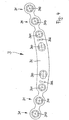
- the first exemplary embodiment of the bone plate 1 according to the invention shown in FIGS. 1 and 2 comprises a stabilization region, which is designed here as an oval web 10. Outside the web 10 eyelets 11 are provided on both sides - in the embodiment shown here two eyelets 11 (which in turn are connected by a narrow connecting web with acting as a stabilizing region web 10 or with each other) - which for fastening the bone plate 1 in the fraktfernfernen Area are provided.
- the holes 110 of the eyelets 11 can either be formed as threaded holes, or they can be formed so that they - as disclosed, for example, in WO-A-00/66012 - have an engagement contour for angularly stable blocking.
- the web 10 initially has a respective compression hole 100 in its edge regions.
- compression holes 100 are formed and their mode of operation are known per se. They allow to compress the ends of the bone fragments on both sides of the fracture gap, which may be conducive to the healing process (compression osteosynthesis).
- the bone plate 1 shown in FIG. 1 in each case has a through hole 101, through which a conventional screw can be screwed through.
- the through-hole 101 may be provided with a thread or with an engagement contour, as known from WO-A-00/66012, in which a corresponding thread of the bone screw engages, but it can also be designed as a hole without thread and Bone screws are used which, apart from the bone thread, do not have a separate thread for engagement in a thread or engagement contour provided in the through hole 101.
- the bone plate 1, possibly after compression, are already fixed relatively near the fracture of the bone fragments.
- a slot 102 is provided in each case.
- This slot 102 causes the bone plate already in the edge regions of the web 10 allows a certain bending of the bone plate to the bone fragments.
- the bone plate in the area of the slot 102 is still more stable against bending of the bone plate in the plane of the plate (greater moment of resistance). as in the area between two eyelets 110 and between the immediately adjacent to the web arranged eyelet 110 and the web 10th
- the length 104 of the web 10 (as such, the distance 104 is referred to because the remaining part at the edge of the web 10 practically each half of an eyelet represents) is here about four times the distance between two adjacent ⁇ senlöcher 110 - and thus the distance between two Screws) from each other.
- the compression holes 100 here have a distance 105 from each other, which corresponds twice the distance between two adjacent eyelet holes 110.
- the web 10 has an overall oval outer contour. Its width decreases starting from the middle, where it has the width 106, to the edge regions, where it has the width 107, slightly, whereby the bone plate in the edge regions of the web 10 is already a little easier to bend to the bone fragments, but still has sufficient stability in terms of immobilization in the fracture gap. Alternatively, other outer contours (already mentioned above) come into consideration.
- the width 106,107 of the web 10 agrees here substantially with the outer diameter of the eyelets 11, which on the one hand ensures sufficient stability of the bone plate 1, on the other hand allows a uniform plate design, which is advantageous from the manufacturing effort ago.
- the thickness 108 of the plate (see Fig. 2) is generally in the range of 0.5 mm to 1.6 mm, preferably in the range of 0.8 m to 1.2 mm, as for so-called Miniplatten is typical, and may be specifically about 1.0 mm.
- FIG. 3 a second embodiment of an inventive bone plate 2 is shown in plan.
- the bone plate 2 shown in Fig. 3 has a ridge 20 which has a compression hole 200 in each of its peripheral regions, but unlike the bone plate discussed above, has no through holes and no slits. Instead, the bone plate 2 in each case three eyelets 21, wherein between the closest to the respective compression hole 200 eyelet 210 although a waisted, but compared to the webs between the other eyelets 210 widened web 202 is provided.
- This web 202 also already allows some bending of the bone plate in this area, but on the other hand still has an increased stability against bending of the bone plate in the plane of the plate (so that this web 202 functionally in some way with the area with the slot 102 of the embodiment according to Fig. 1 is comparable). With respect to the eyelet holes 210 otherwise apply the same statements, which are already set forth above.
- the web 20 is again intended to lie over the fracture gap, the ends of the bone fragments can be stably immobilized by means of compression osteosynthesis in the region of the web 20.
- the bone plate 2 In the region of the eyelets 21 and the narrow webs lying between the eyelets 21, the bone plate 2 can each be well bent against the bone fragments.
- a third embodiment of the inventive bone plate 3 is shown in plan view.
- it is an anatomically preformed bone plate, the longitudinal axis of the plate describes a slight arc. Due to its shape, the bone plate 3 is particularly suitable for use in the anterior region of the lower jaw.
- the bone plate 3 essentially corresponds to the bone plate 1, as described with reference to FIGS. 1 and 2, and therefore with respect to the web 30, the compression holes 300, the through holes 301 in the web 30, the slots 302, as well as with respect to the eyelets 31 with the eyelet holes 310 can be referred to the corresponding parts of the description of the bone plate 1.
Description
Die Erfindung betrifft eine Knochenplatte zur Versorgung einer Fraktur gemäss dem Oberbegriff des unabhängigen Patentanspruchs.The invention relates to a bone plate for the treatment of a fracture according to the preamble of the independent claim.
Bei der Versorgung von Frakturen insbesondere des atrophischen Unterkiefers, die bei Patienten höheren Alters in zunehmendem Masse auftreten, können zahlreiche Probleme auftreten. So stellen beispielsweise lokale Faktoren wie ungenügende Durchblutung durch das häufige Fehlen der Zentralarterie und sklerotische kompaktäre Knochenstümpfe ein Risiko für die Konsolidierung dar. Ausserdem bietet der reduzierte Knochenquerschnitt nicht nur eine geringe Anlagerungsfläche der Enden der Knochenfragmente diesseits und jenseits der Fraktur, sondern erschwert auch das anatomisch korrekte Reponieren der Knochenfragmente. Bei sehr starken Atrophien kann der frakturnahe Knochen so dünn sein, dass grösser dimensionierte Osteosyntheseschrauben von stärkeren Systemen (z.B. von sogenannten mandibularen Trauma- und Rekonstruktionsplatten) nur frakturfern stabil verankert werden können. Eine Kompression der Fraktur ist somit nicht möglich. Bei zahnlosen Patienten ist zudem das Anbringen von Schienenverbänden praktisch nicht möglich. Konservative Therapiemethoden vermögen nur schwer den permanenten suprahyoidalen Muskelzug auf die zahnlosen Fragmente zu kompensieren. Darüberhinaus können auch Erkrankungen, die im fortgeschrittenen Alter vermehrt auftreten, wie z.B. Osteoporose, Diabetes, Niereninsuffizienz und viele andere den.Heilungsverlauf ungünstig beeinflussen. Daneben limitieren im hohen Alter der Allgemeinzustand der Patienten und das hohe Morbiditätsrisiko bei einer längeren Immobilisierung den Umfang und die Dauer operativer Eingriffe.Numerous problems can occur in the treatment of fractures, especially of the atrophic mandible, which are increasingly occurring in older patients. For example, local factors such as insufficient blood flow due to the frequent absence of the central artery and sclerotic compact bone stumps present a risk for consolidation. In addition, the reduced bone cross-section not only provides a small attachment surface to the ends of the bone fragments on either side of the fracture, but also complicates this anatomically correct repositioning of bone fragments. For very severe atrophies, the fractured bone may be so thin that larger sized osteosynthesis screws from stronger systems (e.g., so-called mandibular trauma and reconstruction plates) can only be stably anchored fracture-distant. Compression of the fracture is therefore not possible. In edentulous patients, attaching splints is virtually impossible. Conservative therapy methods are difficult to compensate for the permanent suprahyoid muscle pull on the edentulous fragments. In addition, diseases that are more prevalent in old age, such as Osteoporosis, diabetes, renal insufficiency and many others adversely affect the healing process. In addition, the general condition of the patients and the high risk of morbidity during prolonged immobilization limit the extent and duration of surgical interventions in old age.
Bisher werden verschiedene Therapieansätze verfolgt. Dabei spielt die konservative, nicht-invasive Behandlungsmethode inzwischen eine weniger gewichtige Rolle. Zwei wichtige Ansätze betreffen die Versorgung der Fraktur entweder mit einer sogenannten Miniplatte oder mit einer sogenannten Rekonstruktionsplatte.So far, various therapeutic approaches are being pursued. there the conservative, non-invasive treatment has become less important. Two important approaches concern the treatment of the fracture either with a so-called mini-plate or with a so-called reconstruction plate.
Bei Miniplatten handelt es sich um Knochenplatten mit einer relativ geringen Materialstärke. Solche Miniplatten haben den Vorteil, dass sie bei dem operativen Eingriff oral (also durch den Mund hindurch) eingebracht werden können, es ist also kein Hautschnitt im Kieferbereich des Patienten erforderlich. Die Miniplatten lassen sich gut an die Knochenfragmente anbiegen, aber es ist - wenn überhaupt - nur in wenigen Fällen eine Kompression der Knochenfragmente im Bereich der Fraktur möglich. Allerdings weisen Miniplatten - bedingt durch ihre Materialstärke - in Bezug auf die Stabilität der Immobilisierung der Knochenfragmente im Bereich der Fraktur gewisse Grenzen auf, vor allen Dingen im Hinblick darauf, dass die Patienten möglichst bald nach dem operativen Eingriff wieder kauen sollen und somit erhebliche Kräfte im Frakturbereich wirken.Miniplates are bone plates with a relatively low material thickness. Such miniplates have the advantage that they can be introduced orally (ie, through the mouth) during the surgical procedure, so there is no skin incision in the jaw area of the patient required. The miniplates adapose well to the bone fragments, but compression of the bone fragments in the area of the fracture is possible, if at all, only in a few cases. However, due to their material thickness, miniplates have certain limitations with regard to the stability of the immobilization of the bone fragments in the region of the fracture, in particular in view of the fact that the patients should chew again as soon as possible after the surgical procedure and thus considerable forces in the fracture Fracture area act.
Hier liegen die Vorteile der Rekonstruktionsplatten. Bei diesen Rekonstruktionsplatten handelt es sich um relativ massive Knochenplatten (Materialstärke typischerweise im Bereich von 2.0 - 3.0 mm), die sehr stabil sind und daher auch grosse Kräfte aufnehmen können. Rekonstruktionsplatten lassen sich aber nur schwer an die jeweilige Form des Unterkiefers des Patienten anbiegen. Rekonstruktionsplatten werden dementsprechend auch mit relativ massiven, grossen Schrauben befestigt, die durch entsprechende an der Knochenplatte ausgebildete Ösen hindurch in den Knochen geschraubt werden, was bei ungenügendem Knochenangebot aber nur frakturfern erfolgen kann. Somit ist eine Kompression der Knochenfragmente im Frakturbereich nicht möglich, und ausserdem sind die Rekonstruktionsplatten häufig so gross (da sie eben nur frakturfern befestigt werden können), dass sie einen Hautschnitt im Kieferbereich nötig machen, um das Anbringen der Rekonstruktionsplatte am Unterkiefer zu ermöglichen.Here are the advantages of the reconstruction plates. These reconstruction plates are relatively massive bone plates (material thickness typically in the range of 2.0 - 3.0 mm), which are very stable and therefore can absorb large forces. Reconstruction plates are difficult to bend to the particular shape of the mandible of the patient. Reconstruction plates are accordingly also fixed with relatively massive, large screws, which are screwed through appropriate eyelets formed on the bone plate into the bone, which, however, can only take place fraktfernfern with insufficient bone supply. Thus, a compression of bone fragments in the fracture area is not possible, and also the reconstruction plates are often so large (as they can only be attached to the fracture), they require a skin incision in the area of the jaw to allow attachment of the reconstruction plate to the lower jaw.
Ausgehend von den vorstehend geschilderten Nachteilen der existierenden Knochenplatten liegt der vorliegenden Erfindung die Aufgabe zugrunde, eine Knochenplatte vorzuschlagen, die einerseits in unmittelbarer Nähe zum Frakturspalt ein hohes Mass an Stabilität aufweist und die frakturfern leicht an den Knochen anbiegbar (adaptierbar) ist. Ferner soll die Knochenplatte von ihren Abmessungen her möglichst klein sein, um beim operativen Eingriff ein orales Einbringen der Knochenplatte zu ermöglichen und somit einen Hautschnitt zu vermeiden. Vorzugsweise soll auch eine Kompressionsosteosynthese möglich sein.Based on the above-described disadvantages of existing bone plates, the present invention has for its object to propose a bone plate, on the one hand in the immediate vicinity of the fracture gap has a high degree of stability and the frakturfern easy on the bone bendable (adaptable). Furthermore, the bone plate should be as small in size as possible in order to permit oral insertion of the bone plate during surgical intervention and thus to avoid a skin incision. Preferably also a compression osteosynthesis should be possible.
Diese Aufgabe wird durch eine Knochenplatte gelöst, wie sie durch die Merkmale des unabhängigen Patentanspruchs charakterisiert ist. Vorteilhafte Ausgestaltungen der erfindungsgemässen Knochenplatte ergeben sich aus den Merkmalen der abhängigen Patentansprüche.This object is achieved by a bone plate as characterized by the features of the independent claim. Advantageous embodiments of the inventive bone plate resulting from the features of the dependent claims.
Insbesondere weist die erfindungsgemässe Knochenplatte eine Plattenstärke auf, die im Bereich von 0.5 mm bis 1.6 mm liegt, und umfasst einen Stabilisierungsbereich, der über der Fraktur zu liegen bestimmt ist. Zu beiden Seiten dieses Stabilisierungsbereichs sind Ösen angeordnet, durch deren Löcher hindurch die Schrauben in die Knochenfragmente geschraubt werden können. Eine derartige Knochenplatte mit einem solchen Stabilisierungsbereich erlaubt einerseits eine stabile Immobilisierung im unmittelbaren Bereich der Fraktur, andererseits kann die Knochenplatte frakturfern gut an die Knochenfragmente angebogen (adaptiert) werden. Besonders bevorzugt liegt dabei die Plattenstärke im Bereich von 0.8 mm bis 1.2 mm. Bei solchen Knochenplatten ist es möglich, klein dimensionierte Schrauben zur Befestigung der Knochenplatte zu verwenden, welche auch bei geringem Knochenangebot noch eingeschraubt werden können.In particular, the bone plate according to the invention has a plate thickness which is in the range of 0.5 mm to 1.6 mm and comprises a stabilization region which is intended to lie over the fracture. Eyelets are arranged on both sides of this stabilization area, through whose holes the screws can be screwed into the bone fragments. On the one hand, such a bone plate with such a stabilization region allows a stable immobilization in the immediate area of the fracture, on the other hand, the bone plate can be well bent (adapted) to the bone fragments far away from the fracture. Particularly preferred is the plate thickness in the range of 0.8 mm to 1.2 mm. It is with such bone plates possible to use small-sized screws for fixing the bone plate, which can be screwed in even with low bone supply.
Bei einem Ausführungsbeispiel der erfindungsgemässen Knochenplatte ist der Stabilisierungsbereich als Steg ausgebildet. Die Knochenplatte kann dabei so ausgebildet sein, dass das Widerstandsmoment des Stabilisierungsbereichs bzw. des Stegs gegen ein Verbiegen der Knochenplatte in der Plattenebene gleich gross oder grösser ist als das entsprechende Widerstandsmoment der Knochenplatte im Bereich zwischen den Ösen. Dadurch erhält der Stabilisierungsbereich seine stabilisierende Eigenschaft.In one exemplary embodiment of the bone plate according to the invention, the stabilization region is designed as a web. The bone plate can be designed so that the moment of resistance of the stabilizing region or of the web against bending of the bone plate in the plate plane is equal to or greater than the corresponding moment of resistance of the bone plate in the region between the eyelets. This gives the stabilizing region its stabilizing property.
Die Länge des Stegs kann bis zu etwa sechs mal dem Abstand der Ösen voneinander betragen. Ein derartiger Steg ermöglicht die gute Stabilität der Knochenplatte im unmittelbaren Bereich um den Frakturspalt herum, erlaubt aber andererseits die gute Anbiegbarkeit der Platte in einem frakturferneren Bereich. Dennoch können die Abmessungen (insbesondere die Länge) der Knochenplatte so gehalten werden, dass die Platte beim operativen Eingriff oral zugeführt werden kann, sodass kein Hautschnitt erforderlich ist.The length of the web can be up to about six times the distance of the eyelets from each other. Such a ridge allows good stability of the bone plate in the immediate area around the fracture gap, but on the other hand allows the good availability of the plate in a fraktfernferneren area. Nevertheless, the dimensions (in particular the length) of the bone plate can be kept so that the plate during surgery can be delivered orally, so no skin incision is required.
Bei einem vorteilhaften Ausführungsbeispiel der erfindungsgemässen Knochenplatte ist die Aussenkontur des Stegs oval. Diese Aussenkontur hat sich als besonders vorteilhaft im Hinblick auf die aufzunehmenden Belastungen erwiesen, aber es kommen durchaus auch andere Konturen (z.B. solche Konturen, die im Mittelbereich des Stegs parallel zur Plattenlängsachse verlaufen und dann linear bis hin zu einer geringern Breite am Rand des Stegs abnehmen, oder solche Konturen, die von der Mitte des Stegs direkt linear bis hin zu einer geringeren Breite am Rand des Stegs abnehmen) in Betracht. Auch rechteckförmige Konturen, bei denen Oalso der Steg praktisch bis zu seinen Randregionen hin eine einheitliche Breite aufweist, kommen beispielsweise in Betracht.In an advantageous embodiment of the inventive bone plate, the outer contour of the web is oval. This outer contour has proven to be particularly advantageous in terms of the male loads, but there are quite other contours (eg such contours that are parallel to the plate longitudinal axis in the central region of the web and then linearly decrease to a smaller width at the edge of the web , or such contours that decrease linearly from the middle of the web to a smaller width at the edge of the web). Also rectangular contours, where Oalso the Bridge practically has a uniform width up to its edge regions, for example, come into consideration.
Bei einem vorteilhaften Ausführungsbeispiel der erfindungsgemässen Knochenplatte entspricht die Breite des Stegs im wesentlichen dem Aussendurchmesser der Ösen. Somit kann auch die Breite der Knochenplatte klein gehalten werden, was das Zuführen und Anbringen der Knochenplatte erleichtert, ohne dass dabei die Stabilität der Knochenplatte leidet.In an advantageous embodiment of the inventive bone plate, the width of the web corresponds substantially to the outer diameter of the eyelets. Thus, the width of the bone plate can be kept small, which facilitates the feeding and attaching of the bone plate without the stability of the bone plate suffers.
Bei einem weiteren vorteilhaften Ausführungsbeispiel der erfindungsgemässen Knochenplatte nimmt die Breite des Stegs von der Mitte des Stegs ausgehend hin zu den Randregionen des Stegs ab. In der Mitte des Steges, die unmittelbar über dem Frakturspalt zu liegen bestimmt ist, ist also die Knochenplatte am breitesten. Dort soll sie auch die grössten Belastungen aufnehmen können. Nach aussen hin, also zu den Randregionen des Stegs hin, nimmt die Breite des Stegs ab, dort können die aufzunehmenden Belastungen auch schon wieder teilweise von den Knochenfragmenten aufgenommen werden ohne den Heilungsprozess im Bereich des Frakturspalts zu beeinträchtigen.In a further advantageous embodiment of the bone plate according to the invention, the width of the web decreases starting from the middle of the web towards the edge regions of the web. In the middle of the bridge, which is intended to lie directly above the fracture gap, so the bone plate is widest. There she should also be able to absorb the heaviest loads. Towards the outside, ie towards the edge regions of the bridge, the width of the bridge decreases, where the loads to be absorbed can already be partially absorbed by the bone fragments without impairing the healing process in the region of the fracture gap.
Bei einer vorteilhaften Ausbildung der erfindungsgemässen Knochenplatte können in den Randregionen des Stabilisierungsbereichs bzw. des Stegs Löcher vorgesehen sein, durch welche hindurch Schrauben in die Knochenfragmente geschraubt werden können. Die Knochenplatte kann dann schon relativ frakturnah - mit entsprechend weniger massiven Knochenschrauben - an den Knochenfragmenten befestigt werden. Die Löcher in den Randregionen des Stabilisierungsbereichs bzw. Stegs können insbesondere als Kompressionslöcher ausgebildet sein, oder es können zusätzlich zu herkömmlichen Durchgangslöchern in den Randregionen des Stabilisierungsbereichs bzw. Stegs auch noch separate Kompressionslöcher vorgesehen sein.In an advantageous embodiment of the bone plate according to the invention, holes can be provided in the peripheral regions of the stabilization region or of the web, through which screws can be screwed into the bone fragments. The bone plate can then be attached to the bone fragments relatively close to the fracture - with correspondingly less massive bone screws. The holes in the edge regions of the stabilization region or web can be formed in particular as compression holes, or in addition to conventional through holes in the Edge regions of the stabilization region or web also be provided separate compression holes.
Schliesslich können in den Randregionen des Stabilisierungsbereichs bzw. des Stegs Schlitze vorgesehen sein, um das Anbiegen der Knochenplatte an die Knochenfragmente bereits in diesen Randregionen des Stabilisierungsbereichs bzw. des Stegs zu erleichtern.Finally, slits may be provided in the marginal regions of the stabilization region or the ridge in order to facilitate the bending of the bone plate to the bone fragments already in these marginal regions of the stabilization region or of the ridge.
Weiterhin kann in den Löchern der Ösen und/oder in den Löchern in den Randregionen des Stabilisierungsbereichs bzw. des Stegs eine Eingriffskontur vorgesehen sein zum winkelstabilen Verblocken der Knochenplatte mittels eines an der Schraube vorgesehenen Verblockungsgewindes, wobei die Eingriffskontur ein Einschrauben der Schraube unter verschiedenen Winkeln zulässt. Löcher mit solchen Eingriffskonturen sind beispielsweise aus der WO-A-00/66012 bekannt. Das Vorsehen einer solchen Eingriffskontur ist in mehrerer Hinsicht vorteilhaft. Zum einen sind keine Bohrlehren erforderlich, mit deren Hilfe Löcher für die Schrauben vorgebohrt werden müssen. Vielmehr kann das Vorbohren der Löcher ohne eine Bohrlehre erfolgen oder es können selbstbohrende Schrauben ohne eine Führung (also ohne Vorbohren) direkt in die Knochenfragmente eingeschraubt werden, weil die Eingriffskontur ein Einbringen der Schrauben unter verschiedenen Winkeln erlaubt. Gleichzeitig erlaubt die Eingriffskontur eine stabile Verblockung, sodass ein Selbstlösen der Schraube ausscheidet. Die Verbindung von Schraube und Platte ist grundsätzlich zwar wieder lösbar, jedoch ist hierzu ein deutlich höheres Drehmoment aufzuwenden als bei herkömmlichen Gewindeverbindungen.Furthermore, in the holes of the eyelets and / or in the holes in the edge regions of the stabilization region or of the web, an engagement contour can be provided for locking the bone plate in an angle-stable manner by means of a locking thread provided on the screw, wherein the engagement contour allows the screw to be screwed in at different angles , Holes with such engagement contours are known, for example, from WO-A-00/66012. The provision of such an engagement contour is advantageous in several respects. On the one hand, drilling jigs are not required, with the help of which holes have to be predrilled for the screws. Rather, the pre-drilling of the holes can be done without a drilling jig or it can self-drilling screws without a guide (ie without pre-drilling) are screwed directly into the bone fragments, because the engagement contour allows insertion of the screws at different angles. At the same time, the engagement contour allows a stable blocking, so that self-loosening of the screw eliminates. The connection between screw and plate is basically releasable again, but this is a significantly higher torque than conventional threaded connections.
Weitere vorteilhafte Ausgestaltungen ergeben sich aus der nachfolgenden Beschreibung von Äusführungsbeispielen der erfindungsgemässen Knochenplatte mit Hilfe der Zeichnung.Further advantageous embodiments will become apparent from the following description of Äusführungsbeispielen the bone plate according to the invention with the aid of the drawing.
Es zeigen:
- Fig. 1
- ein erstes Ausführungsbeispiel einer erfindungsgemässen Knochenplatte in Aufsicht,
- Fig. 2
- einen Längsschnitt gemäss der Linie II-II aus Fig. 1 durch das Ausführungsbeispiel der Knochenplatte gemäss Fig. 1,
- Fig. 3
- ein zweites Ausführungsbeispiel einer erfindungsgemässen Knochenplatte in Aufsicht
- und
- Fig. 4
- ein drittes Ausführungsbeispiel einer erfindungsgemässen Knochenplatte in Aufsicht.
- Fig. 1
- a first embodiment of an inventive bone plate in supervision,
- Fig. 2
- 1 shows a longitudinal section along the line II-II from FIG. 1 through the embodiment of the bone plate according to FIG. 1, FIG.
- Fig. 3
- A second embodiment of an inventive bone plate in plan view
- and
- Fig. 4
- A third embodiment of an inventive bone plate in plan view.
Das in Fig. 1 und Fig. 2 gezeigte erste Ausführungsbeispiel der erfindungsgemässen Knochenplatte 1 umfasst einen Stabilisierungsbereich, der hier als ein ovaler Steg 10 ausgebildet ist. Ausserhalb des Stegs 10 sind zu beiden Seiten Ösen 11 vorgesehen - bei dem hier gezeigten Ausführungsbeispiel jeweils zwei Ösen 11 (die ihrerseits durch einen schmalen Verbindungssteg mit dem als Stabilisierungsbereich wirkenden Steg 10 bzw. untereinander verbunden sind) - die zur Befestigung der Knochenplatte 1 im frakturfernen Bereich vorgesehen sind. Die Löcher 110 der Ösen 11 können entweder als Gewindelöcher ausgebildet sein, oder sie können so ausgebildet sein, dass sie - wie beispielsweise in der WO-A-00/66012 offenbart - eine Eingriffskontur zur winkelstabilen Verblockung aufweisen. Sie können auch gar kein Gewinde aufweisen, und die Befestigung der Knochenplatte erfolgt mit Hilfe von Knochenschrauben, die ausser dem Knochengewinde kein separates Gewinde aufweisen zum Eingriff in ein im Ösenloch 110 vorgesehenes Gewinde oder Eingriffskontur. Die Knochenplatte wird dann im Bereich der Öse 11 durch den Schraubenkopf an dem Knochenfragment fixiert.The first exemplary embodiment of the
Der Steg 10 weist in seinen Randregionen zunächst jeweils ein Kompressionsloch 100 auf. Die Art und Weise, wie solche Kompressionslöcher 100 ausgebildet sind sowie ihre Funktionsweise, sind an sich bekannt. Sie erlauben, die Enden der Knochenfragmente diesseits und jenseits des Frakturspalts zu komprimieren, was sich als förderlich für den Heilungsprozess erweisen kann (Kompressionsosteosynthese).The
Weiterhin weist die in Fig. 1 gezeigte Knochenplatte 1 jeweils ein Durchgangsloch 101 auf, durch welches eine konventionelle Schraube hindurch geschraubt werden kann. Das Durchgangsloch 101 kann mit einem Gewinde oder mit einer Eingriffskontur, wie sie aus der WO-A-00/66012 bekannt ist, versehen sein, in welches ein entsprechendes Gewinde der Knochenschraube eingreift, es kann aber auch als ein Loch ohne Gewinde ausgebildet sein und es werden Knochenschrauben verwendet, die ausser dem Knochengewinde kein separates Gewinde aufweisen zum Eingriff in ein im Durchgangsloch 101 vorgesehenes Gewinde oder Eingriffskontur. Somit kann die Knochenplatte 1, gegebenenfalls nach erfolgter Kompression, schon relativ frakturnah an den Knochenfragmenten fixiert werden.Furthermore, the
Zwischen dem jeweiligen Kompressionsloch 100 und dem unmittelbar benachbarten Durchgangloch 101 ist jeweils ein Schlitz 102 vorgesehen. Dieser Schlitz 102 bewirkt, dass die Knochenplatte schon in den Randregionen des Stegs 10 ein gewisses Anbiegen der Knochenplatte an die Knochenfragmente erlaubt. Allerdings ist die Knochenplatte in dem Bereich des Schlitzes 102 gegen ein Verbiegen der Knochenplatte in der Plattenebene immer noch stabiler (grösseres Widerstandsmoment) als im Bereich zwischen zwei Ösen 110 bzw. zwischen der unmittelbar benachbart zum Steg angeordneten Öse 110 und dem Steg 10.Between the
Die Länge 104 des Stegs 10 (als solcher wird hier der Abstand 104 bezeichnet, weil der restliche Teil am Rande des Stegs 10 praktisch jeweils die Hälfte einer Öse darstellt) beträgt hier etwa das Vierfache des Abstands zweier benachbarter Ösenlöcher 110 - und damit des Abstands zweier Schrauben) voneinander. Die Kompressionslöcher 100 haben hier einen Abstand 105 voneinander, der zweimal dem Abstand zweier benachbarter Ösenlöcher 110 entspricht. Somit verbleibt ein genügend grosser Bereich des Stegs 10 zwischen den beiden Kompressionslöchern 100 zur stabilen Fixierung der Enden der Knochenfragmente, und dennoch bleiben die Abmessungen der Knochenplatte 1 insgesamt begrenzt.The
Der Steg 10 weist insgesamt eine ovale Aussenkontur auf. Seine Breite nimmt von der Mitte her beginnend, wo er die Breite 106 aufweist, zu den Randregionen hin, wo er die Breite 107 aufweist, leicht ab, wodurch die Knochenplatte in den Randregionen des Stegs 10 bereits ein wenig leichter an die Knochenfragmente anbiegbar ist, aber dennoch eine ausreichende Stabilität im Hinblick auf die Immobilisierung im Bereich des Frakturspalts aufweist. Alternativ kommen auch andere Aussenkonturen (weiter oben schon erwähnt) in Betracht. Die Breite 106,107 des Stegs 10 stimmt hier im wesentlichen mit dem Aussendurchmesser der Ösen 11 überein, was einerseits eine ausreichende Stabilität der Knochenplatte 1 gewährleistet, andererseits ein einheitliches Plattendesign ermöglicht, was vom herstellungstechnischen Aufwand her vorteilhaft ist.The
Die Stärke 108 der Platte (siehe Fig. 2) liegt grundsätzlich im Bereich von 0.5 mm bis 1.6 mm, bevorzugt liegt sie im Bereich von 0.8 m bis 1.2 mm, wie dies für sogenannten Miniplatten typisch ist, und kann ganz speziell etwa 1.0 mm betragen.The
In Fig. 3 ist ein zweites Ausführungsbeispiel einer erfindungsgemässen Knochenplatte 2 in Aufsicht dargestellt. Die in Fig. 3 gezeigte Knochenplatte 2 weist einen Steg 20 auf, der in seinen Randregionen jeweils ein Kompressionsloch 200 aufweist, jedoch anders als bei der zuvor erläuterten Knochenplatte keine Durchgangslöcher und auch keine Schlitze hat. Stattdessen weist die Knochenplatte 2 jeweils drei Ösen 21 auf, wobei zwischen der am nächsten zum jeweiligen Kompressionsloch 200 gelegenen Öse 210 ein zwar taillierter, aber im Vergleich zu den Stegen zwischen den übrigen Ösen 210 verbreiterter Steg 202 vorgesehen ist. Dieser Steg 202 erlaubt ebenfalls bereits ein gewisses Anbiegen der Knochenplatte in diesem Bereich, weist aber andererseits noch eine erhöhte Stabilität gegen ein Verbiegen der Knochenplatte in der Plattenebene auf (sodass dieser Steg 202 funktionell in gewisser Weise mit dem Bereich mit dem Schlitz 102 des Ausführungsbeispiels gemäss Fig. 1 vergleichbar ist). Bezüglich der Ösenlöcher 210 gelten ansonsten die gleichen Ausführungen, die bereits weiter oben dargelegt sind.In Fig. 3, a second embodiment of an
Der Steg 20 ist erneut dazu bestimmt, über dem Frakturspalt zu liegen, die Enden der Knochenfragmente können mittels Kompressionsosteosynthese im Bereich des Stegs 20 stabil immobilisiert werden. Im Bereich der Ösen 21 bzw. der zwischen den Ösen 21 liegenden schmalen Stege kann die Knochenplatte 2 jeweils gut an die Knochenfragmente angebogen werden.The
In Fig. 4 ist ein drittes Ausführungsbeispiel der erfindungsgemässen Knochenplatte 3 in Aufsicht dargestellt. Bei diesem Ausführungsbeispiel handelt es sich um eine anatomisch vorgeformte Knochenplatte, die Plattenlängsachse beschreibt einen leichten Bogen. Die Knochenplatte 3 ist aufgrund ihrer Form besonders geeignet für den Einsatz im Frontbereich des Unterkiefers.4, a third embodiment of the
Ansonsten entspricht die Knochenplatte 3 im wesentlichen der Knochenplatte 1, wie sie anhand von Fig. 1 und Fig. 2 beschrieben ist, weshalb bezüglich des Stegs 30, der Kompressionslöcher 300, der Durchgangslöcher 301 im Steg 30, der Schlitze 302, sowie bezüglich der Ösen 31 mit den Ösenlöchern 310 auf die entsprechenden Teile der Beschreibung der Knochenplatte 1 verwiesen werden kann.Otherwise, the
Claims (9)
- A bone plate (1; 2; 3) for treating a fracture, especially a fracture of an atrophic mandible, which bone plate (1; 2; 3) comprises a plurality of eyelets (11; 21; 31) through the holes (110; 210; 310) of which screws can be screwed into the bone fragments in order to fasten the bone plate (1; 2; 3) to the bone fragments so that the bone fragments on one side and on the other side of the fracture are maintained in a desired position relative to one another by means of the bone plate (1; 2; 3), said bone plate (1; 2; 3) having a plate thickness (108) in the range of from 0.5 mm to 1.6 mm, and moreover comprising a stabilization zone (10; 20; 30) intended to lie above the fracture, and the eyelets (11; 21; 31) through the holes (110; 210; 310) of which the screws can be screwed into the bone fragments are arranged on both sides of said stabilization zone (10; 20; 30), characterized in that the bone plate (1; 2; 3) as a whole is designed as a single strip, and the stabilization zone is configured as a strip web (10; 20; 30) whose width (106, 107) corresponds substantially to the external diameter of the eyelets (11; 21; 31), and the moment of resistance of the web (10; 20; 30) against bending of the bone plate in the plane of the plate is the same as or greater than the corresponding moment of resistance of the bone plate in the area between the eyelets (11; 21; 31).
- The bone plate as claimed in claim 1, characterized in that the plate thickness (108) lies in the range of from 0.8 mm to 1.2 mm.
- The bone plate as claimed in claim 1 or 2, characterized in that the length (104) of the web is up to about six times the distance of the eyelets (11; 21; 31) from one another.
- The bone plate as claimed in any one of claims 1 through 3, characterized in that the width of the web (10; 20; 30) decreases from the middle of the web (106) to the edge regions (107) of the web.
- The bone plate as claimed in claim 3, characterized in that the outer contour of the web (10; 20; 30) is oval.
- The bone plate as claimed in any one of the preceding claims, characterized in that, in the edge regions of the web (10; 20; 30), holes (100, 101; 200, 201; 300, 301) are provided through which screws can be screwed into the bone fragments.
- The bone plate as claimed in claim 6, characterized in that the holes in the edge regions of the web (10; 20; 30) are designed as compression holes (100; 200; 300).
- The bone plate as claimed in any one of the preceding claims, characterized in that, in the edge regions of the web (10; 30), slits (102; 302) are provided to facilitate bending of the bone plate (1; 3) in these edge regions of the web (10; 30).
- The bone plate as claimed in any one of the preceding claims, characterized in that, in the holes (110; 210; 310) of the eyelets (11; 21; 31) and/or in the holes (100, 101; 200, 201; 300, 301) in the edge regions of the web (10; 20; 30), an engagement contour is provided for blocking the bone plate (1; 2; 3) at a stable angle by means of a blocking thread provided on the screw, said engagement contour allowing the screw to be screwed in at different angles.
Priority Applications (1)
| Application Number | Priority Date | Filing Date | Title |
|---|---|---|---|
| AT02710743T ATE324834T1 (en) | 2002-02-15 | 2002-02-15 | BONE PLATE |
Applications Claiming Priority (1)
| Application Number | Priority Date | Filing Date | Title |
|---|---|---|---|
| PCT/CH2002/000094 WO2003068091A1 (en) | 2002-02-15 | 2002-02-15 | Bone plate |
Publications (2)
| Publication Number | Publication Date |
|---|---|
| EP1474055A1 EP1474055A1 (en) | 2004-11-10 |
| EP1474055B1 true EP1474055B1 (en) | 2006-05-03 |
Family
ID=27671985
Family Applications (1)
| Application Number | Title | Priority Date | Filing Date |
|---|---|---|---|
| EP02710743A Expired - Lifetime EP1474055B1 (en) | 2002-02-15 | 2002-02-15 | Bone plate |
Country Status (5)
| Country | Link |
|---|---|
| US (1) | US20050090825A1 (en) |
| EP (1) | EP1474055B1 (en) |
| AU (1) | AU2002229459A1 (en) |
| DE (1) | DE50206709D1 (en) |
| WO (1) | WO2003068091A1 (en) |
Cited By (1)
| Publication number | Priority date | Publication date | Assignee | Title |
|---|---|---|---|---|
| US8496690B2 (en) | 2009-09-18 | 2013-07-30 | Biomet C.V. | Orthopaedic surgical components |
Families Citing this family (31)
| Publication number | Priority date | Publication date | Assignee | Title |
|---|---|---|---|---|
| FR2874316B1 (en) * | 2004-08-23 | 2006-10-20 | Medicrea Sa | OSTEOSYNTHESIS OR ARTHRODESIS EQUIPMENT |
| US8172886B2 (en) | 2004-12-14 | 2012-05-08 | Depuy Products, Inc. | Bone plate with pre-assembled drill guide tips |
| US20070233113A1 (en) * | 2005-09-16 | 2007-10-04 | Small Bone Innovations, Inc. | Condylar plate |
| WO2007056874A1 (en) | 2005-11-16 | 2007-05-24 | Synthes Gmbh | A through hole for bone fixation device |
| US7935126B2 (en) | 2006-03-20 | 2011-05-03 | Depuy Products, Inc. | Bone plate shaping system |
| US20080015590A1 (en) * | 2006-06-19 | 2008-01-17 | Depuy Products, Inc. | Implant device with placement indicia |
| EP2397093B1 (en) * | 2007-11-02 | 2015-12-02 | Biomet C.V. | Elbow fracture fixation system |
| US8317842B2 (en) | 2007-11-30 | 2012-11-27 | Biomet C.V. | Distal tibia plating system |
| US8118850B2 (en) | 2007-12-10 | 2012-02-21 | Marcus Jeffrey R | Intermaxillary fixation device and method of using same |
| WO2009085560A1 (en) | 2007-12-31 | 2009-07-09 | Marcus Jeffrey R | Intermaxillary fixation device and method of using same |
| FR2936700B1 (en) | 2008-10-02 | 2012-04-13 | Memometal Technologies | ORTHOPEDIC IMPLANT IN THE FORM OF A PLATE TO BE FIXED BETWEEN TWO BONE PARTS |
| US8403966B2 (en) * | 2008-11-24 | 2013-03-26 | Mbd Medical Llc | Clavicle plate and screws |
| US8444679B2 (en) * | 2008-11-24 | 2013-05-21 | Mbd Medical Llc | Clavicle plate and screws |
| DE102009016394B4 (en) * | 2009-04-07 | 2016-02-11 | Merete Medical Gmbh | Device for stable-angle fixation and compression of a fracture site or osteotomy on a bone |
| CA2761857A1 (en) * | 2009-05-12 | 2010-11-18 | Synthes Usa, Llc | Readjustable locking plate hole |
| US8808333B2 (en) * | 2009-07-06 | 2014-08-19 | Zimmer Gmbh | Periprosthetic bone plates |
| US8834532B2 (en) * | 2009-07-07 | 2014-09-16 | Zimmer Gmbh | Plate for the treatment of bone fractures |
| US10390867B2 (en) | 2009-09-18 | 2019-08-27 | Biomet C.V. | Bone plate system and method |
| US8496692B2 (en) * | 2009-09-21 | 2013-07-30 | Jmea Corporation | Locking securing member |
| CA2803585C (en) | 2010-06-23 | 2019-11-26 | Genesis Fracture Care, Inc. | Flexible plate fixation of bone fractures |
| US8790379B2 (en) | 2010-06-23 | 2014-07-29 | Zimmer, Inc. | Flexible plate fixation of bone fractures |
| US8551095B2 (en) * | 2011-02-02 | 2013-10-08 | Bionet Manufacturing, LLC | Bone plate having combination locking and compression screw holes |
| TWI536952B (en) * | 2011-06-27 | 2016-06-11 | 陳瑾惠 | In-situ deformable mini-bone plate and deforming method thereof |
| US9295508B2 (en) | 2012-02-03 | 2016-03-29 | Zimmer, Inc. | Bone plate for elastic osteosynthesis |
| US9545276B2 (en) * | 2013-03-15 | 2017-01-17 | Aristotech Industries Gmbh | Fixation device and method of use for a lapidus-type plantar hallux valgus procedure |
| US9763705B2 (en) * | 2014-10-03 | 2017-09-19 | Globus Medical, Inc. | Orthopedic stabilization devices and methods for installation thereof |
| ES2938683T3 (en) | 2014-12-17 | 2023-04-13 | Medartis Holding Ag | Osteosynthesis plate and surgical sets |
| US10751100B2 (en) | 2014-12-17 | 2020-08-25 | Medartis Holding Ag | Bone screws and surgical sets comprising bone screws |
| WO2016172536A1 (en) * | 2015-04-24 | 2016-10-27 | Biomet Manufacturing, Llc | Clavicle implants |
| CN106667567A (en) * | 2016-12-29 | 2017-05-17 | 上海富笛医疗科技有限公司 | Unequal hole distance bone plate |
| US11324538B2 (en) | 2019-12-04 | 2022-05-10 | Biomet Manufacturing, Llc | Active bone plate |
Family Cites Families (14)
| Publication number | Priority date | Publication date | Assignee | Title |
|---|---|---|---|---|
| US1105105A (en) * | 1912-02-10 | 1914-07-28 | William O'n Sherman | Surgical appliance. |
| DE8706912U1 (en) * | 1987-05-14 | 1987-08-27 | Howmedica Gmbh, 2314 Schoenkirchen, De | |
| US4905679A (en) * | 1988-02-22 | 1990-03-06 | M P Operation, Inc. | Bone fracture reduction device and method of internal fixation of bone fractures |
| DE3923995A1 (en) * | 1989-07-20 | 1991-01-31 | Lutz Biedermann | BONE STABILIZING ELEMENT |
| US4923471A (en) * | 1989-10-17 | 1990-05-08 | Timesh, Inc. | Bone fracture reduction and fixation devices with identity tags |
| US5290281A (en) * | 1992-06-15 | 1994-03-01 | Medicon Eg | Surgical system |
| US6001099A (en) * | 1998-06-08 | 1999-12-14 | Huebner; Randall J. | Bone plate with varying rigidity |
| DE59505733D1 (en) * | 1995-07-03 | 1999-05-27 | Synthes Ag | DEVICE FOR FIXING BONE FRAGMENTS |
| DE19534831C2 (en) * | 1995-09-20 | 1998-10-29 | Medartis Ag | Cutting pliers for cutting implant plates |
| US5690631A (en) * | 1996-09-11 | 1997-11-25 | Walter Lorenz Surgical, Inc. | Multi-configurable plating system |
| US6325803B1 (en) * | 1998-02-18 | 2001-12-04 | Walter Lorenz Surgical, Inc. | Method and apparatus for mandibular osteosynthesis |
| JP2002542875A (en) * | 1999-05-03 | 2002-12-17 | メダルティス・アクチェンゲゼルシャフト | Bone plate that can be blocked |
| DE29909025U1 (en) * | 1999-05-25 | 1999-11-04 | Lipat Consulting Ag Basel | Osteosynthetic bone plate |
| US6440131B1 (en) * | 2001-03-09 | 2002-08-27 | Mayo Foundation For Medical Education And Research | Acetabular bone plate |
-
2002
- 2002-02-15 EP EP02710743A patent/EP1474055B1/en not_active Expired - Lifetime
- 2002-02-15 DE DE50206709T patent/DE50206709D1/en not_active Expired - Fee Related
- 2002-02-15 US US10/503,397 patent/US20050090825A1/en not_active Abandoned
- 2002-02-15 WO PCT/CH2002/000094 patent/WO2003068091A1/en not_active Application Discontinuation
- 2002-02-15 AU AU2002229459A patent/AU2002229459A1/en not_active Abandoned
Cited By (2)
| Publication number | Priority date | Publication date | Assignee | Title |
|---|---|---|---|---|
| US8496690B2 (en) | 2009-09-18 | 2013-07-30 | Biomet C.V. | Orthopaedic surgical components |
| US8685068B2 (en) | 2009-09-18 | 2014-04-01 | Biomet C.V. | Disposable orthopedic surgery kit and components |
Also Published As
| Publication number | Publication date |
|---|---|
| EP1474055A1 (en) | 2004-11-10 |
| WO2003068091A1 (en) | 2003-08-21 |
| AU2002229459A1 (en) | 2003-09-04 |
| DE50206709D1 (en) | 2006-06-08 |
| US20050090825A1 (en) | 2005-04-28 |
Similar Documents
| Publication | Publication Date | Title |
|---|---|---|
| EP1474055B1 (en) | Bone plate | |
| EP1287787B1 (en) | Implant for the fixation of bone fractures | |
| EP1211993B1 (en) | Fixation system for bones | |
| EP0347874B1 (en) | Device for the fixation of a broken bone, in particular in the region of the femoral neck | |
| DE102010055433B4 (en) | Bone screw and device for bone distraction | |
| EP1838230B1 (en) | Angularly stable device for mutually fixing a longitudinal carrier to a bone fixing element | |
| EP1182972B1 (en) | Osteosynthetic bone plate | |
| EP1255498B1 (en) | Bone plate | |
| EP1339335B1 (en) | Device for fixing bones, particularly vertebral bodies, in relation to one another | |
| EP1901671B1 (en) | Osteosynthesis plate comprising through-openings which are inclined in relation to the plane of the plate | |
| AT507271B1 (en) | KNOCHENSCHRAUBENSET | |
| EP0491211A1 (en) | Bone screw | |
| WO2005048857A1 (en) | Set of osteosynthesis plates | |
| DE19750493A1 (en) | Fracture stabilization implant and screw for use in surgery | |
| EP0513943A1 (en) | Implant with pressure surface | |
| EP0685206A1 (en) | Finger bone fixator | |
| EP1455655A1 (en) | Bone anchor | |
| EP1927322B1 (en) | Device for positioning tubular bones | |
| DE60114441T2 (en) | DISTRACTION DEVICE FOR THE UPPER PINE | |
| AT509852B1 (en) | FLEXIBLE HUMERUS NAIL | |
| DE3538645C2 (en) | ||
| WO1990012547A1 (en) | Fixation system for tubular bone fractures | |
| DE3807346C1 (en) | Implant for repositioning and stabilisation of bones | |
| EP2696783B1 (en) | Surgical implant for widening a vertebral canal | |
| EP1648318B1 (en) | Device for fixing a longitudinal carrier to a bone fixing element |
Legal Events
| Date | Code | Title | Description |
|---|---|---|---|
| PUAI | Public reference made under article 153(3) epc to a published international application that has entered the european phase |
Free format text: ORIGINAL CODE: 0009012 |
|
| 17P | Request for examination filed |
Effective date: 20040816 |
|
| AK | Designated contracting states |
Kind code of ref document: A1 Designated state(s): AT BE CH CY DE DK ES FI FR GB GR IE IT LI LU MC NL PT SE TR |
|
| AX | Request for extension of the european patent |
Extension state: AL LT LV MK RO SI |
|
| GRAP | Despatch of communication of intention to grant a patent |
Free format text: ORIGINAL CODE: EPIDOSNIGR1 |
|
| GRAS | Grant fee paid |
Free format text: ORIGINAL CODE: EPIDOSNIGR3 |
|
| GRAA | (expected) grant |
Free format text: ORIGINAL CODE: 0009210 |
|
| AK | Designated contracting states |
Kind code of ref document: B1 Designated state(s): AT CH DE GB LI |
|
| REG | Reference to a national code |
Ref country code: GB Ref legal event code: FG4D Free format text: NOT ENGLISH |
|
| REG | Reference to a national code |
Ref country code: CH Ref legal event code: EP |
|
| REF | Corresponds to: |
Ref document number: 50206709 Country of ref document: DE Date of ref document: 20060608 Kind code of ref document: P |
|
| REG | Reference to a national code |
Ref country code: CH Ref legal event code: NV Representative=s name: A. BRAUN, BRAUN, HERITIER, ESCHMANN AG PATENTANWAE |
|
| GBT | Gb: translation of ep patent filed (gb section 77(6)(a)/1977) |
Effective date: 20060713 |
|
| PLBE | No opposition filed within time limit |
Free format text: ORIGINAL CODE: 0009261 |
|
| STAA | Information on the status of an ep patent application or granted ep patent |
Free format text: STATUS: NO OPPOSITION FILED WITHIN TIME LIMIT |
|
| 26N | No opposition filed |
Effective date: 20070206 |
|
| PGFP | Annual fee paid to national office [announced via postgrant information from national office to epo] |
Ref country code: CH Payment date: 20080226 Year of fee payment: 7 |
|
| PGFP | Annual fee paid to national office [announced via postgrant information from national office to epo] |
Ref country code: GB Payment date: 20080206 Year of fee payment: 7 |
|
| REG | Reference to a national code |
Ref country code: CH Ref legal event code: PFA Owner name: MEDARTIS AG Free format text: MEDARTIS AG#AUSTRASSE 24#4051 BASEL (CH) -TRANSFER TO- MEDARTIS AG#AUSTRASSE 24#4051 BASEL (CH) |
|
| PGFP | Annual fee paid to national office [announced via postgrant information from national office to epo] |
Ref country code: AT Payment date: 20080225 Year of fee payment: 7 |
|
| PGFP | Annual fee paid to national office [announced via postgrant information from national office to epo] |
Ref country code: DE Payment date: 20080429 Year of fee payment: 7 |
|
| REG | Reference to a national code |
Ref country code: CH Ref legal event code: NV Representative=s name: HEPP WENGER RYFFEL AG |
|
| REG | Reference to a national code |
Ref country code: CH Ref legal event code: PL |
|
| GBPC | Gb: european patent ceased through non-payment of renewal fee |
Effective date: 20090215 |
|
| PG25 | Lapsed in a contracting state [announced via postgrant information from national office to epo] |
Ref country code: CH Free format text: LAPSE BECAUSE OF NON-PAYMENT OF DUE FEES Effective date: 20090228 Ref country code: AT Free format text: LAPSE BECAUSE OF NON-PAYMENT OF DUE FEES Effective date: 20090215 Ref country code: LI Free format text: LAPSE BECAUSE OF NON-PAYMENT OF DUE FEES Effective date: 20090228 |
|
| PG25 | Lapsed in a contracting state [announced via postgrant information from national office to epo] |
Ref country code: DE Free format text: LAPSE BECAUSE OF NON-PAYMENT OF DUE FEES Effective date: 20090901 |
|
| PG25 | Lapsed in a contracting state [announced via postgrant information from national office to epo] |
Ref country code: GB Free format text: LAPSE BECAUSE OF NON-PAYMENT OF DUE FEES Effective date: 20090215 |