EP1473821A2 - Netzpulsstromrichter - Google Patents
Netzpulsstromrichter Download PDFInfo
- Publication number
- EP1473821A2 EP1473821A2 EP04002976A EP04002976A EP1473821A2 EP 1473821 A2 EP1473821 A2 EP 1473821A2 EP 04002976 A EP04002976 A EP 04002976A EP 04002976 A EP04002976 A EP 04002976A EP 1473821 A2 EP1473821 A2 EP 1473821A2
- Authority
- EP
- European Patent Office
- Prior art keywords
- pulse
- mains
- converter
- converters
- line
- Prior art date
- Legal status (The legal status is an assumption and is not a legal conclusion. Google has not performed a legal analysis and makes no representation as to the accuracy of the status listed.)
- Granted
Links
Images
Classifications
-
- H—ELECTRICITY
- H02—GENERATION; CONVERSION OR DISTRIBUTION OF ELECTRIC POWER
- H02M—APPARATUS FOR CONVERSION BETWEEN AC AND AC, BETWEEN AC AND DC, OR BETWEEN DC AND DC, AND FOR USE WITH MAINS OR SIMILAR POWER SUPPLY SYSTEMS; CONVERSION OF DC OR AC INPUT POWER INTO SURGE OUTPUT POWER; CONTROL OR REGULATION THEREOF
- H02M5/00—Conversion of AC power input into AC power output, e.g. for change of voltage, for change of frequency, for change of number of phases
- H02M5/02—Conversion of AC power input into AC power output, e.g. for change of voltage, for change of frequency, for change of number of phases without intermediate conversion into DC
- H02M5/04—Conversion of AC power input into AC power output, e.g. for change of voltage, for change of frequency, for change of number of phases without intermediate conversion into DC by static converters
- H02M5/22—Conversion of AC power input into AC power output, e.g. for change of voltage, for change of frequency, for change of number of phases without intermediate conversion into DC by static converters using discharge tubes with control electrode or semiconductor devices with control electrode
- H02M5/25—Conversion of AC power input into AC power output, e.g. for change of voltage, for change of frequency, for change of number of phases without intermediate conversion into DC by static converters using discharge tubes with control electrode or semiconductor devices with control electrode using devices of a thyratron or thyristor type requiring extinguishing means
- H02M5/257—Conversion of AC power input into AC power output, e.g. for change of voltage, for change of frequency, for change of number of phases without intermediate conversion into DC by static converters using discharge tubes with control electrode or semiconductor devices with control electrode using devices of a thyratron or thyristor type requiring extinguishing means using semiconductor devices only
- H02M5/2573—Conversion of AC power input into AC power output, e.g. for change of voltage, for change of frequency, for change of number of phases without intermediate conversion into DC by static converters using discharge tubes with control electrode or semiconductor devices with control electrode using devices of a thyratron or thyristor type requiring extinguishing means using semiconductor devices only with control circuit
-
- H—ELECTRICITY
- H02—GENERATION; CONVERSION OR DISTRIBUTION OF ELECTRIC POWER
- H02M—APPARATUS FOR CONVERSION BETWEEN AC AND AC, BETWEEN AC AND DC, OR BETWEEN DC AND DC, AND FOR USE WITH MAINS OR SIMILAR POWER SUPPLY SYSTEMS; CONVERSION OF DC OR AC INPUT POWER INTO SURGE OUTPUT POWER; CONTROL OR REGULATION THEREOF
- H02M1/00—Details of apparatus for conversion
- H02M1/12—Arrangements for reducing harmonics from AC input or output
Definitions
- the invention relates to a line pulse converter for Use in a parallel connection of several such Mains pulse converter especially for energy exchange between high voltage electrical networks, with a especially on minimizing harmonics aligned pulse pattern.
- Such a line pulse converter is from the Publication "Highly dynamic vector control with adaptive line harmonic adjustment for high power voltage source converters "by J. Janning and H.P. Beck, Electrical Engineering 81 (1998), pages 309 to 315.
- a line pulse converter in the pulse pattern ⁇ i (u, v, w) are used with regard to a Minimizing harmonics are optimized.
- the index i refers to the different switching angles one period, while the indices u, v, w are the three strands or phases of the high-voltage network.
- the pulse pattern ⁇ i (u, v, w) only refers to the Control of a single fundamental wave. For one entire control range thus exist Plurality of different optimized pulse patterns.
- Chapter 9 shows an example of a converter for the exchange of energy between a three-phase 110 kV, 50 Hz supply network and a single-phase 15 kV, 16 2/3 Hz Railway network specified.
- the object of the invention is to provide a line pulse converter create with that in a parallel connection of several such line pulse converters even then Reduction of harmonics is achievable when the number of simultaneously switched on Mains pulse converter changed.
- each of the parallel Mains pulse converter flexible with that pulse pattern operated, not only for him a reduction of harmonics, but also in the With regard to the other line pulse converters an advantage is.
- the respective pulse pattern depends on the Number of line pulse converters currently switched on as well as according to the index of the person concerned Power pulse converter. So it is possible in the Parallel connection of the line pulse converter in flexible Assign a harmonic reduction even then reach when the number of simultaneously switched on mains pulse converter changed. The Harmonics can thus be kept to a minimum at all times can be reduced.
- the parallel-connected mains pulse converter via a Communication device coupled together. So that is it is possible that the individual line pulse converters Query number and / or the index itself or that the Number and / or the index of the communication device determined and passed on to the line pulse converter becomes.
- the pulse pattern generator for everyone Possibility of combining the number and the index associated pulse patterns are available. Particularly useful it is when the possible pulse patterns in the Pulse pattern generator are stored. That way it is possible to determine quickly with little effort to ensure the current pulse pattern.
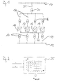
- FIG. 1 is a three-phase 110 kV, 50 Hz Supply network 10 shown that over four Mains pulse converters 11, 12, 13, 14 connected in parallel with a single-phase 110 kV, 16 2/3 Hz rail network 15 coupled is.
- Each of the line pulse converters 11, 12, 13, 14 is included transformers 16, 17 and switches connected in series 18, 19 connected. All four connected in parallel Mains pulse converters 11, 12, 13, 14 are together in series to another transformer 20 and another Switch 21 switched. Between the transformer 20 and the switches 18 is an example of an intermediate voltage of 20.5 kV, 50 Hz available.
- the line pulse converters 11, 12, 13, 14 are via a Communication device 22 coupled to each other, so that a data exchange between the line pulse converters 11, 12, 13, 14 can take place.
- each of the line pulse converters 11, 12, 13, 14 of the figure 1 contains a regulation, such as that in of the publication explained at the beginning and is described. As explained at the beginning, come in this regulation pulse pattern ⁇ i (u, v, w) for the three phases to be used with a view to minimizing Harmonics are optimized. These pulse patterns will be determined as follows:
- FIG. 2 shows a pulse pattern generator 25, which as input signals a number n of the same time switched on line pulse converter and an index k of affected mains pulse converter are supplied.
- the pulse pattern generator 25 generates the output signal Pulse patterns ⁇ i (u, v, w), which are then different from those mentioned above Regulation will continue to be used.
- the number n of simultaneously switched on Mains pulse converter is for each of the main pulse converters 11, 12, 13, 14 using the communication device 22 determined.
- the communication device 22 can be trained so that they are in predetermined time Distances of each of the line pulse converters 11, 12, 13, 14 in With regard to its switch-on status, then to everyone Mains pulse converters 11, 12, 13, 14 the number n of Mains pulse converter switched on at the same time tell. It is also possible that each of the Mains pulse converter 11, 12, 13, 14 the others Mains pulse converter with regard to their switch-on state queries and from it the number n of the same time switched on line pulse converter determined.
- the number n the line pulse converter switched on at the same time be a maximum of 4.
- the index k of the respective line pulse converter is for each of the line pulse converters 11, 12, 13, 14 using the Communication device 22 can be determined.
- each of the line pulse converters 11, 12, 13, 14 be designed such that it is due to the above explained query of the switch-on states of the others Mains pulse converter itself determines which index k er owns currently.
- Teen can also Mains pulse converter 11, 12, 13, 14 using the index k further queries or with the help of queries from Determine communication device 22.
- the pulse pattern generator 25 can for each The number n and the index k can be combined associated pulse pattern ⁇ i (u, v, w) for the three phases Will be provided. To this end, for everyone possible combination the associated pulse pattern in advance have been determined and in the pulse pattern generator 25 be saved. It is also possible that the Pulse pattern generator 25 for every possible combination associated pulse patterns are determined in real time.
- This pulse pattern is then controlled by the Mains pulse converter 12 used.
- the Mains pulse converter 11 would thus the pulse pattern ⁇ 31, i provided by the pulse pattern generator 25 get and use.
- appropriate pulse pattern ⁇ 33, i would either for the Mains pulse converter 13 or the main pulse converter 14 apply, depending on which of the two last-mentioned line pulse converter 13, 14 currently is switched on.
- the pulse pattern generator 25 can possibly only once to be available. In this case they would be dependent from the number n and the index k selected pulse patterns via the communication device 22, for example Request to the respective line pulse converter 11, 12, 13, 14 are handed over. It is also possible that everyone the line pulse converter 11, 12, 13, 14 with one each own pulse pattern generator 25 is provided. In this case each of the line pulse converters 11, 12, 13, 14 simultaneously and independently of the others Mains pulse converters the pulse patterns that apply to him determine.
- the stored in the pulse pattern generator 25 or in Pulse patterns determined in real time are generated for each of the described combination options in advance or current calculated. In these calculations, not only the individual line pulse converters with regard to reduced Harmonics designed, but it will also Interaction of the four line pulse converters 11, 12, 13, 14 taken into account in this regard.
- the pulse pattern can be determined in various ways be performed. One way is to use the Pulse pattern according to the explanations at the beginning mentioned publication taking into account the to calculate the above conditions.
- Each of the switched on works in operation Mains pulse converter 11, 12, 13, 14 according to the each pulse pattern currently determined. If one of the Mains pulse converter 11, 12, 13, 14 from one turned on in an off state or vice versa about, so this is about the Communication device 22 the other Mains pulse converters communicated. The now up to date switched-on line pulse converters can then new ones Determine current pulse patterns and from this point in time use. The switched off line pulse converter no longer determines the current pulse pattern.
Landscapes
- Engineering & Computer Science (AREA)
- Power Engineering (AREA)
- Inverter Devices (AREA)
- Power Conversion In General (AREA)
- Particle Accelerators (AREA)
- Electrotherapy Devices (AREA)
Abstract
Description
- Figur 1
- zeigt ein schematisches Blockschaltbild eines Ausführungsbeispiels einer Parallelschaltung von mehreren erfindungsgemäßen Netzpulsstromrichtern, und
- Figur 2
- zeigt eine schematische Darstellung eines erfindungsgemäßen Pulsmustergenerators für den Betrieb der einzelnen Netzpulsstromrichter der Figur 1.
Claims (10)
- Netzpulsstromrichter (11) zur Verwendung in einer Parallelschaltung mehrerer derartiger Netzpulsstromrichter (11, 12, 13, 14) insbesondere für den Energieaustausch zwischen elektrischen Hochspannungsnetzen, mit einem insbesondere auf eine Minimierung von Oberschwingungen ausgerichteten Pulsmuster, dadurch gekennzeichnet, dass ein Pulsmustergenerator (25) vorgesehen ist, der das Pulsmuster (αi(u,v,w)) in Abhängigkeit von einer Anzahl (n) der gleichzeitig eingeschalteten Netzpulsstromrichter (11, 12, 13, 14) und von einem Index (k) des jeweils betroffenen Netzpulsstromrichters (11) zur Verfügung stellt.
- Netzpulsstromrichter (11) nach Anspruch 1, dadurch gekennzeichnet, dass die parallelgeschalteten Netzpulsstromrichter (11, 12, 13, 14) über eine Kommunikationseinrichtung (22) miteinander gekoppelt sind, und dass der Netzpulsstromrichter (11) die Anzahl (n) der gleichzeitig eingeschalteten Netzpulsstromrichter (11, 12, 13, 14) abfragt.
- Netzpulsstromrichter (11) nach Anspruch 2, dadurch gekennzeichnet, dass der Netzpulsstromrichter (11) den Index (k) des jeweils betroffenen Netzpulsstromrichters (11) aus der Abfrage ermittelt.
- Netzpulsstromrichter (11) nach Anspruch 1, dadurch gekennzeichnet, dass die parallelgeschalteten Netzpulsstromrichter (11, 12, 13, 14) über eine Kommunikationseinrichtung (22) miteinander gekoppelt sind, und dass die Kommunikationseinrichtung (22) die Anzahl (n) der gleichzeitig eingeschalteten Netzpulsstromrichter (11, 12, 13, 14) ermittelt.
- Netzpulsstromrichter (11) nach Anspruch 4, dadurch gekennzeichnet, dass die Kommunikationseinrichtung (22) den Index (k) des jeweils betroffenen Netzpulsstromrichters (11) ermittelt.
- Netzpulsstromrichter (11) nach einem der vorstehenden Ansprüche, dadurch gekennzeichnet, dass der Pulsmustergenerator (25) für jede Kombinationsmöglichkeit der Anzahl (n) und des Index (k) das zugehörige Pulsmuster (αi(u,v,w)) zur Verfügung stellt.
- Netzpulsstromrichter (11) nach Anspruch 6, dadurch gekennzeichnet, dass die möglichen Pulsmuster (αi(u,v,w)) in dem Pulsmustergenerator (25) abgespeichert sind.
- Parallelschaltung von mehreren Netzpulsstromrichtern (11, 12, 13, 14) insbesondere für den Energieaustausch zwischen elektrischen Hochspannungsnetzen, wobei jeder der Netzpulsstromrichter (11, 12, 13, 14) mit einem insbesondere auf eine Minimierung von Oberschwingungen ausgerichteten Pulsmuster versehen ist, dadurch gekennzeichnet, dass ein Pulsmustergenerator (25) vorgesehen ist, der das Pulsmuster (αi(u,v,w)) in Abhängigkeit von einer Anzahl (n) der gleichzeitig eingeschalteten Netzpulsstromrichter (11, 12, 13, 14) und von einem Index (k) des jeweils betroffenen Netzpulsstromrichters (11, 12, 13, 14) zur Verfügung stellt.
- Verfahren zum Betreiben eines Netzpulsstromrichters (11), wobei der Netzpulsstromrichter (11) zur Verwendung in einer Parallelschaltung mehrerer derartiger Netzpulsstromrichter (11, 12, 13, 14) insbesondere für den Energieaustausch zwischen elektrischen Hochspannungsnetzen vorgesehen ist, und wobei das Verfahren ein insbesondere auf eine Minimierung von Oberschwingungen ausgerichtetes Pulsmuster ermittelt, dadurch gekennzeichnet, dass das Pulsmuster (αi(u,v,w)) in Abhängigkeit von einer Anzahl (n) der gleichzeitig eingeschalteten Netzpulsstromrichter (11, 12, 13, 14) und von einem Index (k) des jeweils betroffenen Netzpulsstromrichters (11) zur Verfügung gestellt wird.
- Verfahren nach Anspruch 9, dadurch gekennzeichnet, dass die möglichen Pulsmuster (αi(u,v,w)) vorab unter Berücksichtigung des Zusammenwirkens der parallelgeschalteten Netzpulsstromrichter (11, 12, 13, 14) und im Hinblick auf verminderte Oberschwingungen ermittelt werden.
Applications Claiming Priority (2)
| Application Number | Priority Date | Filing Date | Title |
|---|---|---|---|
| DE2003119207 DE10319207A1 (de) | 2003-04-29 | 2003-04-29 | Netzpulsstromrichter |
| DE10319207 | 2003-04-29 |
Publications (3)
| Publication Number | Publication Date |
|---|---|
| EP1473821A2 true EP1473821A2 (de) | 2004-11-03 |
| EP1473821A3 EP1473821A3 (de) | 2005-11-30 |
| EP1473821B1 EP1473821B1 (de) | 2009-09-16 |
Family
ID=32981157
Family Applications (1)
| Application Number | Title | Priority Date | Filing Date |
|---|---|---|---|
| EP20040002976 Expired - Lifetime EP1473821B1 (de) | 2003-04-29 | 2004-02-11 | Netzpulsstromrichter |
Country Status (2)
| Country | Link |
|---|---|
| EP (1) | EP1473821B1 (de) |
| DE (2) | DE10319207A1 (de) |
Family Cites Families (2)
| Publication number | Priority date | Publication date | Assignee | Title |
|---|---|---|---|---|
| DE3213778A1 (de) * | 1982-04-08 | 1983-10-13 | Licentia Patent-Verwaltungs-Gmbh, 6000 Frankfurt | Netzkupplung zum austausch elektrischer energie zwischen einem dreiphasennetz hoeherer frequenz und einem einphasennetz niedrigerer frequenz |
| KR100430930B1 (ko) * | 2000-02-25 | 2004-05-12 | 가부시끼가이샤 도시바 | Pwm 제어형 전력 변환 장치 |
-
2003
- 2003-04-29 DE DE2003119207 patent/DE10319207A1/de not_active Ceased
-
2004
- 2004-02-11 DE DE200450010057 patent/DE502004010057D1/de not_active Expired - Lifetime
- 2004-02-11 EP EP20040002976 patent/EP1473821B1/de not_active Expired - Lifetime
Also Published As
| Publication number | Publication date |
|---|---|
| EP1473821B1 (de) | 2009-09-16 |
| DE10319207A1 (de) | 2004-12-02 |
| EP1473821A3 (de) | 2005-11-30 |
| DE502004010057D1 (de) | 2009-10-29 |
Similar Documents
| Publication | Publication Date | Title |
|---|---|---|
| DE1942045C3 (de) | Geregeltes, von einer dreiphasigen Wechselspannung gespeistes Netzgerät | |
| EP0677917A2 (de) | Schaltungsanordnung mit einem Wechselrichter | |
| EP2709257A2 (de) | Stromrichterschaltung und Verfahren zur Steuerung der Stromrichterschaltung | |
| DE2904817A1 (de) | Verfahren und schaltung zur steuerung eines hochspannungs-gleichstromsystems | |
| EP0852841B1 (de) | Netzfreundlicher stromrichtergesteuerter, spannungseinprägender schrägtransformator grosser leistung | |
| CH644476A5 (de) | Leistungswechselrichter. | |
| DE2605185C3 (de) | Einphasen-Stromrichter | |
| EP2660964A1 (de) | Stromversorgungsanordnung mit einer ersten und einer zweiten Stromversorgungseinrichtung, wobei die zweite Stromversorgungseinrichtung an die erste Stromversorgungseinrichtung angeschlossen ist | |
| DE2800928C3 (de) | Schaltungsanordnung für den Fahrbetrieb sowie für den Nutz- und Widerstandsbremsbetrieb einer aus einem Gleichspannungsnetz gespeisten Wechselstrommaschine | |
| WO2015000725A1 (de) | Energiespeichersystem mit erhöhter abgegebener elektrischer leistung | |
| EP1473821B1 (de) | Netzpulsstromrichter | |
| DE3035305A1 (de) | Wechselrichterschaltung fuer den antrieb eines synchronmotors | |
| EP0428035B1 (de) | Dreiphasen-Direktumrichter | |
| EP0270920A2 (de) | Verfahren und Vorrichtung zur Erzeugung von Sende-Stromsignalen in einem Wechselstromverteilungsnetz | |
| EP0588011A1 (de) | Rückspeisefähige Beschaltung für Zweipunkt- und Dreipunkt-Wechselrichter sowie Verfahren zur Rückspeisung der Beschaltungsenergie | |
| EP2928056B1 (de) | Verfahren und Vorrichtung zum Betreiben eines modularen Stromrichters mit einstellbarer Flankensteilheit der Schaltvorgänge in den Submodulen | |
| EP2928055B1 (de) | Modularer Stromrichter und Verfahren zur Erzeugung einer sinusförmigen Ausgangsspannung mit reduziertem Oberschwingungsgehalt | |
| WO2021037537A1 (de) | Ansteuerverfahren für einen gleichspannungswandler und gleichspannungswandler | |
| DE2455765B1 (de) | Verfahren und vorrichtung zur stufenlosen steuerung oder regelung der drehzahl und/oder des drehmoments einer drehstrom-asynchronmaschine, die von einem zwischenkreisumrichter gespeist ist | |
| EP1126592B1 (de) | Elektrische Schaltung zur Steuerung einer Mehrzahl parallelgeschalteter Umrichter | |
| EP4329180A1 (de) | Steuerverfahren für einen modularen bremssteller | |
| WO1997008601A1 (de) | Verfahren zur steuerung der abgegebenen leistung einer elektrischen schaltung, insbesondere einer sinusquelle | |
| DE102020113208A1 (de) | Verfahren zum Betreiben einer Antriebseinrichtung sowie entsprechende Antriebseinrichtung | |
| DE102007022315A1 (de) | Schaltungsanordnung mit einer Mehrzahl von Hochsetzstellern und Ansteuerverfahren hierzu | |
| DE2418922C3 (de) | Anordnung zur Steuerung der Drehzahl eines von einem Umrichter gespeisten Wechselstrommotors |
Legal Events
| Date | Code | Title | Description |
|---|---|---|---|
| PUAI | Public reference made under article 153(3) epc to a published international application that has entered the european phase |
Free format text: ORIGINAL CODE: 0009012 |
|
| AK | Designated contracting states |
Kind code of ref document: A2 Designated state(s): AT BE BG CH CY CZ DE DK EE ES FI FR GB GR HU IE IT LI LU MC NL PT RO SE SI SK TR |
|
| AX | Request for extension of the european patent |
Extension state: AL LT LV MK |
|
| PUAL | Search report despatched |
Free format text: ORIGINAL CODE: 0009013 |
|
| AK | Designated contracting states |
Kind code of ref document: A3 Designated state(s): AT BE BG CH CY CZ DE DK EE ES FI FR GB GR HU IE IT LI LU MC NL PT RO SE SI SK TR |
|
| AX | Request for extension of the european patent |
Extension state: AL LT LV MK |
|
| RIC1 | Information provided on ipc code assigned before grant |
Ipc: 7H 02M 5/257 A Ipc: 7H 02M 1/12 B |
|
| 17P | Request for examination filed |
Effective date: 20060112 |
|
| AKX | Designation fees paid |
Designated state(s): DE FR GB |
|
| 17Q | First examination report despatched |
Effective date: 20080207 |
|
| RAP1 | Party data changed (applicant data changed or rights of an application transferred) |
Owner name: CONVERTEAM GMBH |
|
| GRAP | Despatch of communication of intention to grant a patent |
Free format text: ORIGINAL CODE: EPIDOSNIGR1 |
|
| GRAS | Grant fee paid |
Free format text: ORIGINAL CODE: EPIDOSNIGR3 |
|
| GRAA | (expected) grant |
Free format text: ORIGINAL CODE: 0009210 |
|
| AK | Designated contracting states |
Kind code of ref document: B1 Designated state(s): DE FR GB |
|
| REG | Reference to a national code |
Ref country code: GB Ref legal event code: FG4D Free format text: NOT ENGLISH |
|
| REF | Corresponds to: |
Ref document number: 502004010057 Country of ref document: DE Date of ref document: 20091029 Kind code of ref document: P |
|
| PLBE | No opposition filed within time limit |
Free format text: ORIGINAL CODE: 0009261 |
|
| STAA | Information on the status of an ep patent application or granted ep patent |
Free format text: STATUS: NO OPPOSITION FILED WITHIN TIME LIMIT |
|
| 26N | No opposition filed |
Effective date: 20100617 |
|
| REG | Reference to a national code |
Ref country code: DE Ref legal event code: R082 Ref document number: 502004010057 Country of ref document: DE Representative=s name: RUEGER, BARTHELT & ABEL PATENTANWAELTE, DE |
|
| REG | Reference to a national code |
Ref country code: FR Ref legal event code: PLFP Year of fee payment: 13 |
|
| REG | Reference to a national code |
Ref country code: FR Ref legal event code: PLFP Year of fee payment: 14 |
|
| PGFP | Annual fee paid to national office [announced via postgrant information from national office to epo] |
Ref country code: DE Payment date: 20170227 Year of fee payment: 14 Ref country code: FR Payment date: 20170223 Year of fee payment: 14 |
|
| PGFP | Annual fee paid to national office [announced via postgrant information from national office to epo] |
Ref country code: GB Payment date: 20170227 Year of fee payment: 14 |
|
| REG | Reference to a national code |
Ref country code: DE Ref legal event code: R119 Ref document number: 502004010057 Country of ref document: DE |
|
| GBPC | Gb: european patent ceased through non-payment of renewal fee |
Effective date: 20180211 |
|
| REG | Reference to a national code |
Ref country code: FR Ref legal event code: ST Effective date: 20181031 |
|
| PG25 | Lapsed in a contracting state [announced via postgrant information from national office to epo] |
Ref country code: DE Free format text: LAPSE BECAUSE OF NON-PAYMENT OF DUE FEES Effective date: 20180901 |
|
| PG25 | Lapsed in a contracting state [announced via postgrant information from national office to epo] |
Ref country code: FR Free format text: LAPSE BECAUSE OF NON-PAYMENT OF DUE FEES Effective date: 20180228 Ref country code: GB Free format text: LAPSE BECAUSE OF NON-PAYMENT OF DUE FEES Effective date: 20180211 |