EP1473540A1 - Verfahren zur Bestimmung des Niveaus mehrerer Messpunkte sowie Anordnung dafür - Google Patents
Verfahren zur Bestimmung des Niveaus mehrerer Messpunkte sowie Anordnung dafür Download PDFInfo
- Publication number
- EP1473540A1 EP1473540A1 EP04007930A EP04007930A EP1473540A1 EP 1473540 A1 EP1473540 A1 EP 1473540A1 EP 04007930 A EP04007930 A EP 04007930A EP 04007930 A EP04007930 A EP 04007930A EP 1473540 A1 EP1473540 A1 EP 1473540A1
- Authority
- EP
- European Patent Office
- Prior art keywords
- light beam
- intensity distribution
- cross
- measuring point
- detector surface
- Prior art date
- Legal status (The legal status is an assumption and is not a legal conclusion. Google has not performed a legal analysis and makes no representation as to the accuracy of the status listed.)
- Granted
Links
- 238000000034 method Methods 0.000 title claims description 18
- 238000009826 distribution Methods 0.000 claims abstract description 28
- 239000004065 semiconductor Substances 0.000 claims description 4
- 238000001514 detection method Methods 0.000 claims description 2
- 239000000835 fiber Substances 0.000 claims description 2
- 230000003287 optical effect Effects 0.000 claims description 2
- 238000005259 measurement Methods 0.000 description 5
- 238000004519 manufacturing process Methods 0.000 description 2
- 238000006073 displacement reaction Methods 0.000 description 1
- 238000011156 evaluation Methods 0.000 description 1
- 230000005484 gravity Effects 0.000 description 1
Images



Classifications
-
- G—PHYSICS
- G01—MEASURING; TESTING
- G01C—MEASURING DISTANCES, LEVELS OR BEARINGS; SURVEYING; NAVIGATION; GYROSCOPIC INSTRUMENTS; PHOTOGRAMMETRY OR VIDEOGRAMMETRY
- G01C15/00—Surveying instruments or accessories not provided for in groups G01C1/00 - G01C13/00
- G01C15/002—Active optical surveying means
Definitions
- the present invention relates to a method and an arrangement for determination of the level of several measuring points according to the preamble of claim 1 and 7 respectively.
- the beam direction of a laser exactly in one desired azimuthal direction of rotation is steered.
- the beam of a laser diode the is emitted vertically upwards, deflected by a pentagonal prism by 90 °.
- the Pentagonal prism rotates the laser beam in a plane perpendicular to the direction of emission.
- Determining the respective angle of rotation of this rotation is an encoder with a round Encoder plate used and the angle of rotation is evaluated via an encoder sensor.
- an additional Measuring method when using cylinder coordinates whose height z is above a horizontal reference plane e.g. the plane of rotation of the laser beam
- a horizontal reference plane e.g. the plane of rotation of the laser beam
- the light beam is preferably an emission beam Semiconductor laser, in which the emitted light is already a preferred direction of the Cross-sectional intensity distribution included.
- the detector is preferably a CCD chip and the element for deflecting the light beam through 90 ° is preferably a pentagonal prism.
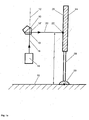
- Fig. 1a shows a schematic side view of an arrangement according to the invention, wherein a here not shown holder carries a pentagonal prism 10 which on the holder by one vertical axis 12 is rotatable and fixable.
- a light source 14 which is preferably a Is semiconductor laser and is fixed with a bracket, not shown, above a level 15 occurs a beam in a direction 16, which preferably points vertically upwards, and strikes a surface 18 of the pentagonal prism 10.
- the plane 15 can e.g. one for putting up one Machine-specific floor slab of a building that has local unevenness should be measured.
- a pentagonal prism has the well-known property that a Light beam hitting one of the surfaces 18 or 18 ', regardless of the angle of incidence is always reflected rotated by 90 ° and is thus deflected without the orientation of the to change the corresponding image, with a change in the angle of incidence only to one Parallel displacement of the deflected beam leads.
- others can Deflection elements are used, such as a normal plane mirror Angle mirror or a correspondingly curved fiber bundle.
- the directions 16 and 20 of the incident are in the example shown and reflected beam in a plane that is perpendicular to the two surfaces 18 and 18 '. After this deflection, the beam falls horizontally at a height z above the level 15 at one Impact point 22 on a detector 24 with a detector surface 26.
- the detector surface 26 preferably consists of a CCD chip or, in particular, which records two-dimensionally a C-MOS sensor and is designed so that by means of a plurality of pixels spatial image of the cross-sectional intensity distribution of the incident beam is determined can be.
- the holder 28 can be moved on the level 15 and in this way on one Measuring point 29 can be positioned on level 15. With the one described below The method should be the vertical level of the measuring point 29 with respect to the level 15 and the horizontal position of the measuring point 29 can be detected in the plane 15.
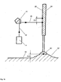
- Fig. 1b shows a situation corresponding to that in Fig. 1a, with the measuring point 30 now an unevenness 32 of level 15.
- the horizontal beam in direction 20 now hits a height reduced by ⁇ z on the detector surface 26 if the unevenness is a height ⁇ z having.
- the respective height can be easily determined by reading the CCD chip, by focusing on the light intensity distribution with an image processing software is determined.
- the relative Changes in altitude can be gained directly.
- the vertical deviations different measuring points with respect to level 15 are recorded.
- each measuring point still has to two further spatial coordinates can be determined. This can e.g. in cylindrical coordinates happen where the two additional coordinates are then the angle ⁇ (azimuth) and the Radius R are.
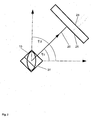
- FIG. 2 shows a top view of the arrangement from FIG. 1 a.
- the distracted Beam in direction 20 is directed at an angle ⁇ 1 with respect to a reference direction Radiated detector 24.
- ⁇ 1 is 45 ° here.
- the use of a pentagonal prism for Beam deflection has the advantage that any tilting of the prism with respect to the Vertical at best to a beam offset, but not to a tilt from the Horizontal leads out. This can cause errors in determining the horizontal Deviation of the measuring points can be kept low.
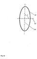
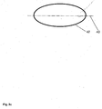
- the beam emitted along direction 16 has a preferred direction of it Cross-sectional intensity distribution.
- the beam emitted along the direction 16 has Lines of constant light intensity with an elliptical shape (one of which is exemplary with the Reference numeral 31 designates in FIG. 2 with a preferred direction (i.e. with a Longitudinal axis of symmetry, the ellipse).
- ⁇ 1 45 °
- ⁇ 2 90 °
- the pentagonal prism 10 rotates, it rotates around the vertical one Axis 16 through 360 ° also the preferred direction 40 of the cross-sectional intensity distribution on the Detector surface 26 (which of course must be carried along in such a way that the sensor detects the Cross-sectional intensity distribution can record) by 360 °.
- the image processing software which also includes the The focus of the cross-sectional intensity distribution on the detector surface 26 and thus the Height of the point of incidence of the laser beam on the detector surface 26 determined. For this For example, the outline contour of the intensity distribution is first determined and based on the center of gravity can then be determined.
- the various measuring points are still used to determine the position the radial distance of the measuring points to the origin axis - which here by the beam in Direction 16 is required. Methods for this are known to the person skilled in the art and should therefore not be explained in more detail.
- Fig. 4 shows a perspective view of the arrangement of Fig. 1a, 2 and 3a for one 45 ° rotation angle. As shown, the preferred direction 40 is Cross-sectional intensity distribution also rotated 45 ° to the horizontal.
- FIG. 5 shows a representation similar to FIG. 4, but for a rotation angle of 135 °. Accordingly, the preferred direction 40 of the cross-sectional intensity distribution is 135 ° rotated against the horizontal.
- the advantage of the method and the device according to the invention is that Possibility of using the detector 24 to measure the z-coordinate of the point of impact 22 is used to determine a second spatial coordinate, namely the angle ⁇ .
- An additional sensor system such as an encoder used according to the prior art with a round encoder plate and encoder sensor for determining the angle of rotation ⁇ can be omitted. Production costs and the size of the arrangement can thus be significantly reduced and furthermore, the measuring method as a whole can be simplified.
- the advantage of using a semiconductor laser is the fact that here Cross-sectional intensity distribution of the laser beam already has a preferred direction and one it does not have to be generated by an additional lens system.
- the cross-sectional distribution which must not be radially symmetrical, can be determined by a Cylinder lens or a lens system are formed.
- the cross-sectional intensity distribution not elliptical, but has a non-centrally symmetrical shape, as defined by a corresponding optical element, e.g. through a triangular diaphragm.
- the advantage of this embodiment is that it can also be used to measure the full angle of 360 ° can be carried out, which is only up to 180 ° with a centrally symmetrical shape is possible.
- a non-centrally symmetrical form of Cross-sectional intensity distribution could then, for example, in the representation of FIG. 5 a distinction is made as to whether the angle of rotation ⁇ is 135 ° as shown or instead in Truth is 315 °.
Landscapes
- Physics & Mathematics (AREA)
- Engineering & Computer Science (AREA)
- General Physics & Mathematics (AREA)
- Radar, Positioning & Navigation (AREA)
- Remote Sensing (AREA)
- Length Measuring Devices By Optical Means (AREA)
- Measurement Of Optical Distance (AREA)
- Photometry And Measurement Of Optical Pulse Characteristics (AREA)
Abstract
Description
Claims (15)
- Verfahren zur Bestimmung des Niveaus mindestens zweier Messpunkte (29, 30), wobei ein Lichtstrahl entlang einer ersten Richtung (16) erzeugt wird, der Lichtstrahl um 90° zur ersten Richtung in eine zweite Richtung (20) umgelenkt wird, wobei die zweite Richtung entsprechend der Lage des Messpunkts um einen Drehwinkel um eine von der ersten Richtung gebildeten Achse gedreht wird, dadurch gekennzeichnet, dass der Lichtstrahl eine Querschnittsintensitätsverteilung (42) mit einer Vorzugsrichtung (40) aufweist und nach der Umlenkung in die zweite Richtung auf eine Detektorfläche (26) fällt, die nacheinander an jedem Messpunkt (29, 30) postiert wird, wobei das Auftreffniveau des Lichtstrahls und die Orientierung der Vorzugsrichtung der Querschnittsintensitätsverteilung des Lichtstrahls auf der Detektorfläche für jeden Messpunkt bestimmt werden, und wobei der Drehwinkel für jeden Messpunkt aus der jeweiligen Orientierung der Vorzugsrichtung auf der Detektorfläche bestimmt wird.
- Verfahren gemäß Anspruch 1, dadurch gekennzeichnet, dass die Niveaus der Messpunkte (29, 30) als Abweichung von einer Referenzebene (15) bestimmt werden, wobei die erste Richtung (16) senkrecht zu der Referenzebene steht.
- Verfahren gemäß Anspruch 1, dadurch gekennzeichnet, dass aus den gemessenen Niveaus der Messpunkte (29, 30) die Referenzebene (15) als Ausgleichsebene bezüglich der Niveaus bestimmt wird.
- Verfahren gemäß Anspruch 1, dadurch gekennzeichnet, dass ein Linsensystem oder eine Blende zwischen Lichtquelle und Detektor gebracht wird, um die Vorzugsrichtung der Querschnittsintensitätsverteilung des Lichtstrahls zu erzeugen.
- Verfahren gemäß Anspruch 1, dadurch gekennzeichnet, dass als Lichtquelle (14) ein Halbleiterlaser benutzt wird, dessen Lichtintensität im Fernfeld eine Vorzugsrichtung (40) der Querschnittsintensitätsverteilung aufweist.
- Verfahren gemäß Anspruch 1, dadurch gekennzeichnet, dass der Detektor als Flächensensor (24) ausgebildet ist.
- Anordnung zur Bestimmung des Niveaus mindestens zweier Messpunkte (29, 30) , einer Detektorfläche (26) und mit einer Lichtquelle (16) , die zur Erzeugung eines Lichtstrahls entlang einer ersten Richtung (16) ausgebildet ist, einer Umlenkeinrichtung (10) , um den Lichtstrahl um 90° zur ersten Richtung in eine zweite Richtung (20) umzulenken, wobei die Umlenkeinrichtung um eine von der ersten Richtung gebildeten Achse (12) drehbar ist, um die zweite Richtung entsprechend der Lage des jeweiligen Messpunkts zu drehen dadurch gekennzeichnet, dass der Lichtstrahl eine Querschnittsintensitätsverteilung (40) mit einer Vorzugsrichtung (42), hat, und nach der Umlenkung in die zweite Richtung auf die nacheinander an jedem Messpunkt (29, 30) anzuordnende Detektorfläche (26) fällt, und wobei die Detektorfläche ausgebildet ist, um das Auftreffniveau des Lichtstrahls und die Orientierung der Vorzugsrichtung der Querschnittsintensitätsverteilung des Lichtstrahls auf der Detektorfläche für jeden Messpunkt zu bestimmen.
- Anordnung gemäß Anspruch 7, dadurch gekennzeichnet, dass die Umlenkeinrichtung aus einem Pentagonalprisma (10), einem Spiegel oder einem Faserbündel besteht.
- Anordnung gemäß Anspruch 7, dadurch gekennzeichnet, dass die Detektorfläche (26) ein Bilderfassungssensor (24) mit mehreren Spalten und Zeilen von lichtempfindlichen Elementen ist.
- Anordnung gemäß Anspruch 9, dadurch gekennzeichnet, dass der Bilderfassungssensor (24) ein CCD-Chip oder ein C-MOS-Sensor ist.
- Anordnung gemäß Anspruch 7, dadurch gekennzeichnet, dass die Lichtquelle (14) ein Laser ist.
- Anordnung gemäß Anspruch 11, dadurch gekennzeichnet, dass die Lichtquelle (14) als Laserdiode ausgebildet ist, wobei der Lichtstrahl im Fernfeld der Laserdiode eine elliptische Querschnittsintensitätsverteilung hat.
- Anordnung gemäß einem der Ansprüche 7 bis 12, dadurch gekennzeichnet, dass sich zwischen der Lichtquelle (14) und der Umlenkeinrichtung (10) ein Linsensystem mit mindestens einer Zylinderlinse befindet.
- Anordnung gemäß einem der Ansprüchen 7 bis 12, dadurch gekennzeichnet, dass sich zwischen der Lichtquelle (14) und der Umlenkeinrichtung (10) mindestens ein optischen Element mit einer nicht radialsymmetrischen Öffnung befindet.
- Anordnung gemäß Anspruch 14, dadurch gekennzeichnet, dass die Öffnung nicht zentralsymmetrisch ist.
Applications Claiming Priority (2)
| Application Number | Priority Date | Filing Date | Title |
|---|---|---|---|
| DE10319369 | 2003-04-29 | ||
| DE10319369A DE10319369A1 (de) | 2003-04-29 | 2003-04-29 | Verfahren zur Bestimmung des Niveaus mehrerer Messpunkte sowie Anordnung dafür |
Publications (2)
| Publication Number | Publication Date |
|---|---|
| EP1473540A1 true EP1473540A1 (de) | 2004-11-03 |
| EP1473540B1 EP1473540B1 (de) | 2011-11-02 |
Family
ID=32981166
Family Applications (1)
| Application Number | Title | Priority Date | Filing Date |
|---|---|---|---|
| EP04007930A Expired - Lifetime EP1473540B1 (de) | 2003-04-29 | 2004-04-01 | Verfahren zur Bestimmung des Niveaus mehrerer Messpunkte sowie Anordnung dafür |
Country Status (4)
| Country | Link |
|---|---|
| US (1) | US7212294B2 (de) |
| EP (1) | EP1473540B1 (de) |
| AT (1) | ATE532034T1 (de) |
| DE (1) | DE10319369A1 (de) |
Cited By (1)
| Publication number | Priority date | Publication date | Assignee | Title |
|---|---|---|---|---|
| DE102013007661A1 (de) | 2013-05-06 | 2014-11-06 | Prüftechnik Dieter Busch AG | Vorrichtung zum Ermitteln der Lage von mechanischen Elementen |
Families Citing this family (4)
| Publication number | Priority date | Publication date | Assignee | Title |
|---|---|---|---|---|
| US8092660B2 (en) * | 2004-12-03 | 2012-01-10 | Cardinal Cg Company | Methods and equipment for depositing hydrophilic coatings, and deposition technologies for thin films |
| JP4651731B2 (ja) * | 2009-07-29 | 2011-03-16 | 西進商事株式会社 | レーザースクライブ加工方法 |
| DE102014204917A1 (de) * | 2014-03-17 | 2015-09-17 | Prüftechnik Dieter Busch Aktiengesellschaft | Verfahren und Vorrichtung zum Ermitteln des Abstands eines Lichtstrahls von einem Punkt auf einer Körperoberfläche mittels eines Lichtsensors |
| DE102017128588A1 (de) | 2017-12-01 | 2019-06-06 | Prüftechnik Dieter Busch AG | System und verfahren zur erfassung und darstellung von messpunkten auf einer körperfläche |
Citations (4)
| Publication number | Priority date | Publication date | Assignee | Title |
|---|---|---|---|---|
| US3649122A (en) * | 1969-03-28 | 1972-03-14 | Zeiss Stiftung | Method and apparatus for measuring the position coordinates of one point in relation to a reference point |
| JP2000046551A (ja) * | 1998-07-24 | 2000-02-18 | Asahi Optical Co Ltd | レーザ測量装置 |
| JP2000213937A (ja) * | 1999-01-21 | 2000-08-04 | Asahi Optical Co Ltd | レ―ザ測量装置 |
| EP1245926A2 (de) * | 2001-03-28 | 2002-10-02 | Kabushiki Kaisha TOPCON | Laserzielvorrichtung mit Neigungsmessvorrichtung |
Family Cites Families (18)
| Publication number | Priority date | Publication date | Assignee | Title |
|---|---|---|---|---|
| FR2287678A1 (fr) * | 1974-10-12 | 1976-05-07 | Ibm | Procede et dispositif pour mesurer un angle notamment pour le reglage de tetes magnetiques dans les memoires a disques |
| JPS5469455A (en) * | 1977-11-14 | 1979-06-04 | Tokyo Optical | Device for measuring astigmatism axis and refracting power |
| JPS5492232A (en) * | 1977-12-28 | 1979-07-21 | Canon Inc | Camera |
| US4297031A (en) * | 1979-09-26 | 1981-10-27 | Hamar M R | Apparatus and process for sweeping a flat optical light plane |
| US4441818A (en) * | 1980-04-23 | 1984-04-10 | Pharos Ab | Deflection unit |
| US4483618A (en) * | 1982-05-24 | 1984-11-20 | Hamar M R | Laser measurement system, virtual detector probe and carriage yaw compensator |
| US4498773A (en) * | 1983-05-04 | 1985-02-12 | Rockwell International Corporation | Pencil beam interferometer |
| DE3601179A1 (de) * | 1986-01-17 | 1987-07-23 | Nestle & Fischer | Nivelliersystem mit rotierendem laserstrahl |
| US4878754A (en) * | 1986-10-16 | 1989-11-07 | Tokyo Keiki Co. Ltd. | Method of and apparatus for measuring irregularities of road surface |
| JPH0721411B2 (ja) * | 1987-01-20 | 1995-03-08 | 株式会社ソキア | 光水準測量装置 |
| US5530549A (en) * | 1994-05-24 | 1996-06-25 | Spatialmetrix Corp. | Probing retroreflector and methods of measuring surfaces therewith |
| US5825555A (en) * | 1994-09-19 | 1998-10-20 | Asahi Kogaku Kogyo Kabushiki Kaisha | Beam projecting apparatus |
| JPH09210687A (ja) * | 1996-01-31 | 1997-08-12 | Topcon Corp | レーザレベル装置 |
| EP1022508B1 (de) | 1999-01-22 | 2004-04-14 | Leica Geosystems AG | Verriegelbares Stativ |
| US6519029B1 (en) * | 1999-03-22 | 2003-02-11 | Arc Second, Inc. | Low cost transmitter with calibration means for use in position measurement systems |
| JP2001021354A (ja) * | 1999-07-09 | 2001-01-26 | Topcon Corp | 光学位置検出装置 |
| DE19941030C1 (de) | 1999-08-28 | 2001-04-26 | Hilti Ag | Laseranordnung für ein mehrstrahliges Laserrichtgerät |
| JP4601798B2 (ja) * | 2000-10-06 | 2010-12-22 | 株式会社トプコン | 位置測定設定システム |
-
2003
- 2003-04-29 DE DE10319369A patent/DE10319369A1/de not_active Withdrawn
-
2004
- 2004-04-01 EP EP04007930A patent/EP1473540B1/de not_active Expired - Lifetime
- 2004-04-01 AT AT04007930T patent/ATE532034T1/de active
- 2004-04-28 US US10/833,349 patent/US7212294B2/en not_active Expired - Fee Related
Patent Citations (4)
| Publication number | Priority date | Publication date | Assignee | Title |
|---|---|---|---|---|
| US3649122A (en) * | 1969-03-28 | 1972-03-14 | Zeiss Stiftung | Method and apparatus for measuring the position coordinates of one point in relation to a reference point |
| JP2000046551A (ja) * | 1998-07-24 | 2000-02-18 | Asahi Optical Co Ltd | レーザ測量装置 |
| JP2000213937A (ja) * | 1999-01-21 | 2000-08-04 | Asahi Optical Co Ltd | レ―ザ測量装置 |
| EP1245926A2 (de) * | 2001-03-28 | 2002-10-02 | Kabushiki Kaisha TOPCON | Laserzielvorrichtung mit Neigungsmessvorrichtung |
Non-Patent Citations (2)
| Title |
|---|
| PATENT ABSTRACTS OF JAPAN vol. 2000, no. 05 14 September 2000 (2000-09-14) * |
| PATENT ABSTRACTS OF JAPAN vol. 2000, no. 11 3 January 2001 (2001-01-03) * |
Cited By (3)
| Publication number | Priority date | Publication date | Assignee | Title |
|---|---|---|---|---|
| DE102013007661A1 (de) | 2013-05-06 | 2014-11-06 | Prüftechnik Dieter Busch AG | Vorrichtung zum Ermitteln der Lage von mechanischen Elementen |
| EP2801789A1 (de) | 2013-05-06 | 2014-11-12 | Prüftechnik Dieter Busch AG | Vorrichtung zum Ermitteln der Lage von mechanischen Elementen |
| US9841274B2 (en) | 2013-05-06 | 2017-12-12 | Pruftechnik Dieter Busch Ag | Device for determining the location of mechanical elements |
Also Published As
| Publication number | Publication date |
|---|---|
| ATE532034T1 (de) | 2011-11-15 |
| DE10319369A1 (de) | 2004-12-02 |
| US20050002044A1 (en) | 2005-01-06 |
| EP1473540B1 (de) | 2011-11-02 |
| US7212294B2 (en) | 2007-05-01 |
Similar Documents
| Publication | Publication Date | Title |
|---|---|---|
| DE102013213547B4 (de) | Kalibriereinrichtung und Kalibrierverfahren für eine Vorrichtung zum schichtweisen Herstellen eines Objekts | |
| EP1618426B1 (de) | Verfahren und anordnung zur bestimmung der fokusposition bei der abbildung einer probe | |
| DE19941638C1 (de) | Geodätisches Gerät mit Laseranordnung | |
| DE2256736A1 (de) | Verfahren zur automatischen oberflaechenprofilmessung und vorrichtung zur durchfuehrung des verfahrens | |
| EP2458363A1 (de) | Messung der Positionen von Krümmungsmittelpunkten optischer Flächen eines mehrlinsigen optischen Systems | |
| EP2458326A1 (de) | Rotationslaser | |
| EP2695374A1 (de) | Verfahren zum bestimmen von justierungsabweichungen eines bilddatenerfassungs-chips einer optischen kamera sowie entsprechende justierprüfvorrichtungen | |
| DE102011012611A1 (de) | Verfahren und Vorrichtung zur berührungslosen Messung eines Winkels | |
| DE102022109740A1 (de) | Verfahren und Vorrichtung zur Durchführung optischer Kohärenzmessungen für eine Überwachung eines Bearbeitungsprozesses eines Werkstücks | |
| EP1854506B1 (de) | Überprüfung der Positioniergenauigkeit eines Patiententisches in Bezug auf ein Isozentrum | |
| DE10232230A1 (de) | Verfahren zum Vermessen des Intensitätsprofils eines Elektronenstrahls, insbesondere eines Strahls eines Elektronenstrahlbearbeitungsgeräts, und/oder zum Vermessen einer Optik für einen Elektronenstrahl und/oder zum Justieren einer Optik für einen Elektronenstrahl, Meßstruktur für ein solches Verfahren und Elektronenstrahlbearbeitungsgerät | |
| EP1473540B1 (de) | Verfahren zur Bestimmung des Niveaus mehrerer Messpunkte sowie Anordnung dafür | |
| WO2001014826A1 (de) | Verfahren und vorrichtung zum erfassen eines biegewinkels an einem werkstück | |
| DE102014010667B4 (de) | Verfahren und Vorrichtung zur Messung der Form einer Wellenfront eines optischen Strahlungsfeldes | |
| DE10117390A1 (de) | Vorrichtung zur quantitativen Beurteilung der räumlichen Lage zweier Maschinenteile, Werkstücke oder anderer Gegenstände relativ zueinander | |
| DE102006053359C5 (de) | Optoelektronische Sensoranordnung und Verfahren zum Justieren einer optoelektronischen Sensoranordnung | |
| EP1459033A2 (de) | Verfahren zur dreidimensionalen messung einer oberfläche | |
| CH697319B1 (de) | Verfahren und Vorrichtung zum geometrischen Kalibrieren von optoelektronischen Messbildkameras. | |
| DE102012014520A1 (de) | Vorrichtung zum Ermitteln der Lage von mechanischen Elementen | |
| DE10143812A1 (de) | Vorrichtung und Verfahren zur quantitativen Beurteilung der räumlichen Lage zweier Maschinenteile, Werkstücke oder anderer Gegenstände relativ zueinander | |
| DE102016013550B3 (de) | Profilmesssystem für eine Rauheits- und Konturmessung an einer Oberfläche eines Werkstücks | |
| DE4121326C2 (de) | Orthogonal-Meßverfahren | |
| DE102020130746B4 (de) | Vorrichtung und Verfahren zur Untersuchung einer Fläche | |
| DE102013210736A1 (de) | Vorrichtung zum Ermitteln der Lage von mechanischen Elementen | |
| DE102004028191B4 (de) | Verfahren und Vorrichtung zur quantitativen Erfassung der Lage der optischen Achse eines optoelektronischen Sensorsystems |
Legal Events
| Date | Code | Title | Description |
|---|---|---|---|
| PUAI | Public reference made under article 153(3) epc to a published international application that has entered the european phase |
Free format text: ORIGINAL CODE: 0009012 |
|
| AK | Designated contracting states |
Kind code of ref document: A1 Designated state(s): AT BE BG CH CY CZ DE DK EE ES FI FR GB GR HU IE IT LI LU MC NL PL PT RO SE SI SK TR |
|
| AX | Request for extension of the european patent |
Extension state: AL HR LT LV MK |
|
| 17P | Request for examination filed |
Effective date: 20050303 |
|
| AKX | Designation fees paid |
Designated state(s): AT BE BG CH CY CZ DE DK EE ES FI FR GB GR HU IE IT LI LU MC NL PL PT RO SE SI SK TR |
|
| GRAP | Despatch of communication of intention to grant a patent |
Free format text: ORIGINAL CODE: EPIDOSNIGR1 |
|
| GRAS | Grant fee paid |
Free format text: ORIGINAL CODE: EPIDOSNIGR3 |
|
| GRAA | (expected) grant |
Free format text: ORIGINAL CODE: 0009210 |
|
| AK | Designated contracting states |
Kind code of ref document: B1 Designated state(s): AT BE BG CH CY CZ DE DK EE ES FI FR GB GR HU IE IT LI LU MC NL PL PT RO SE SI SK TR |
|
| REG | Reference to a national code |
Ref country code: GB Ref legal event code: FG4D Free format text: NOT ENGLISH |
|
| REG | Reference to a national code |
Ref country code: CH Ref legal event code: EP |
|
| REG | Reference to a national code |
Ref country code: IE Ref legal event code: FG4D |
|
| REG | Reference to a national code |
Ref country code: DE Ref legal event code: R096 Ref document number: 502004013014 Country of ref document: DE Effective date: 20120112 |
|
| REG | Reference to a national code |
Ref country code: SE Ref legal event code: TRGR |
|
| REG | Reference to a national code |
Ref country code: NL Ref legal event code: VDEP Effective date: 20111102 |
|
| PG25 | Lapsed in a contracting state [announced via postgrant information from national office to epo] |
Ref country code: PL Free format text: LAPSE BECAUSE OF FAILURE TO SUBMIT A TRANSLATION OF THE DESCRIPTION OR TO PAY THE FEE WITHIN THE PRESCRIBED TIME-LIMIT Effective date: 20111102 Ref country code: SI Free format text: LAPSE BECAUSE OF FAILURE TO SUBMIT A TRANSLATION OF THE DESCRIPTION OR TO PAY THE FEE WITHIN THE PRESCRIBED TIME-LIMIT Effective date: 20111102 Ref country code: GR Free format text: LAPSE BECAUSE OF FAILURE TO SUBMIT A TRANSLATION OF THE DESCRIPTION OR TO PAY THE FEE WITHIN THE PRESCRIBED TIME-LIMIT Effective date: 20120203 Ref country code: NL Free format text: LAPSE BECAUSE OF FAILURE TO SUBMIT A TRANSLATION OF THE DESCRIPTION OR TO PAY THE FEE WITHIN THE PRESCRIBED TIME-LIMIT Effective date: 20111102 Ref country code: PT Free format text: LAPSE BECAUSE OF FAILURE TO SUBMIT A TRANSLATION OF THE DESCRIPTION OR TO PAY THE FEE WITHIN THE PRESCRIBED TIME-LIMIT Effective date: 20120302 |
|
| REG | Reference to a national code |
Ref country code: IE Ref legal event code: FD4D |
|
| PG25 | Lapsed in a contracting state [announced via postgrant information from national office to epo] |
Ref country code: CY Free format text: LAPSE BECAUSE OF FAILURE TO SUBMIT A TRANSLATION OF THE DESCRIPTION OR TO PAY THE FEE WITHIN THE PRESCRIBED TIME-LIMIT Effective date: 20111102 |
|
| PG25 | Lapsed in a contracting state [announced via postgrant information from national office to epo] |
Ref country code: CZ Free format text: LAPSE BECAUSE OF FAILURE TO SUBMIT A TRANSLATION OF THE DESCRIPTION OR TO PAY THE FEE WITHIN THE PRESCRIBED TIME-LIMIT Effective date: 20111102 Ref country code: BG Free format text: LAPSE BECAUSE OF FAILURE TO SUBMIT A TRANSLATION OF THE DESCRIPTION OR TO PAY THE FEE WITHIN THE PRESCRIBED TIME-LIMIT Effective date: 20120202 Ref country code: EE Free format text: LAPSE BECAUSE OF FAILURE TO SUBMIT A TRANSLATION OF THE DESCRIPTION OR TO PAY THE FEE WITHIN THE PRESCRIBED TIME-LIMIT Effective date: 20111102 Ref country code: IE Free format text: LAPSE BECAUSE OF FAILURE TO SUBMIT A TRANSLATION OF THE DESCRIPTION OR TO PAY THE FEE WITHIN THE PRESCRIBED TIME-LIMIT Effective date: 20111102 Ref country code: SK Free format text: LAPSE BECAUSE OF FAILURE TO SUBMIT A TRANSLATION OF THE DESCRIPTION OR TO PAY THE FEE WITHIN THE PRESCRIBED TIME-LIMIT Effective date: 20111102 Ref country code: DK Free format text: LAPSE BECAUSE OF FAILURE TO SUBMIT A TRANSLATION OF THE DESCRIPTION OR TO PAY THE FEE WITHIN THE PRESCRIBED TIME-LIMIT Effective date: 20111102 |
|
| PG25 | Lapsed in a contracting state [announced via postgrant information from national office to epo] |
Ref country code: RO Free format text: LAPSE BECAUSE OF FAILURE TO SUBMIT A TRANSLATION OF THE DESCRIPTION OR TO PAY THE FEE WITHIN THE PRESCRIBED TIME-LIMIT Effective date: 20111102 Ref country code: IT Free format text: LAPSE BECAUSE OF FAILURE TO SUBMIT A TRANSLATION OF THE DESCRIPTION OR TO PAY THE FEE WITHIN THE PRESCRIBED TIME-LIMIT Effective date: 20111102 |
|
| PLBE | No opposition filed within time limit |
Free format text: ORIGINAL CODE: 0009261 |
|
| STAA | Information on the status of an ep patent application or granted ep patent |
Free format text: STATUS: NO OPPOSITION FILED WITHIN TIME LIMIT |
|
| 26N | No opposition filed |
Effective date: 20120803 |
|
| BERE | Be: lapsed |
Owner name: PRUFTECHNIK DIETER BUSCH A.G. Effective date: 20120430 |
|
| REG | Reference to a national code |
Ref country code: DE Ref legal event code: R097 Ref document number: 502004013014 Country of ref document: DE Effective date: 20120803 |
|
| PG25 | Lapsed in a contracting state [announced via postgrant information from national office to epo] |
Ref country code: MC Free format text: LAPSE BECAUSE OF NON-PAYMENT OF DUE FEES Effective date: 20120430 |
|
| REG | Reference to a national code |
Ref country code: CH Ref legal event code: PL |
|
| PG25 | Lapsed in a contracting state [announced via postgrant information from national office to epo] |
Ref country code: CH Free format text: LAPSE BECAUSE OF NON-PAYMENT OF DUE FEES Effective date: 20120430 Ref country code: LI Free format text: LAPSE BECAUSE OF NON-PAYMENT OF DUE FEES Effective date: 20120430 Ref country code: BE Free format text: LAPSE BECAUSE OF NON-PAYMENT OF DUE FEES Effective date: 20120430 |
|
| PG25 | Lapsed in a contracting state [announced via postgrant information from national office to epo] |
Ref country code: ES Free format text: LAPSE BECAUSE OF FAILURE TO SUBMIT A TRANSLATION OF THE DESCRIPTION OR TO PAY THE FEE WITHIN THE PRESCRIBED TIME-LIMIT Effective date: 20120213 |
|
| REG | Reference to a national code |
Ref country code: AT Ref legal event code: MM01 Ref document number: 532034 Country of ref document: AT Kind code of ref document: T Effective date: 20120401 |
|
| PG25 | Lapsed in a contracting state [announced via postgrant information from national office to epo] |
Ref country code: FI Free format text: LAPSE BECAUSE OF FAILURE TO SUBMIT A TRANSLATION OF THE DESCRIPTION OR TO PAY THE FEE WITHIN THE PRESCRIBED TIME-LIMIT Effective date: 20111102 |
|
| PG25 | Lapsed in a contracting state [announced via postgrant information from national office to epo] |
Ref country code: AT Free format text: LAPSE BECAUSE OF NON-PAYMENT OF DUE FEES Effective date: 20120401 |
|
| PG25 | Lapsed in a contracting state [announced via postgrant information from national office to epo] |
Ref country code: TR Free format text: LAPSE BECAUSE OF FAILURE TO SUBMIT A TRANSLATION OF THE DESCRIPTION OR TO PAY THE FEE WITHIN THE PRESCRIBED TIME-LIMIT Effective date: 20111102 |
|
| PG25 | Lapsed in a contracting state [announced via postgrant information from national office to epo] |
Ref country code: LU Free format text: LAPSE BECAUSE OF NON-PAYMENT OF DUE FEES Effective date: 20120401 |
|
| PG25 | Lapsed in a contracting state [announced via postgrant information from national office to epo] |
Ref country code: HU Free format text: LAPSE BECAUSE OF FAILURE TO SUBMIT A TRANSLATION OF THE DESCRIPTION OR TO PAY THE FEE WITHIN THE PRESCRIBED TIME-LIMIT Effective date: 20040401 |
|
| REG | Reference to a national code |
Ref country code: FR Ref legal event code: PLFP Year of fee payment: 12 |
|
| PGFP | Annual fee paid to national office [announced via postgrant information from national office to epo] |
Ref country code: GB Payment date: 20150423 Year of fee payment: 12 Ref country code: DE Payment date: 20150422 Year of fee payment: 12 Ref country code: SE Payment date: 20150423 Year of fee payment: 12 |
|
| PGFP | Annual fee paid to national office [announced via postgrant information from national office to epo] |
Ref country code: FR Payment date: 20150422 Year of fee payment: 12 |
|
| REG | Reference to a national code |
Ref country code: DE Ref legal event code: R119 Ref document number: 502004013014 Country of ref document: DE |
|
| REG | Reference to a national code |
Ref country code: SE Ref legal event code: EUG |
|
| GBPC | Gb: european patent ceased through non-payment of renewal fee |
Effective date: 20160401 |
|
| REG | Reference to a national code |
Ref country code: FR Ref legal event code: ST Effective date: 20161230 |
|
| PG25 | Lapsed in a contracting state [announced via postgrant information from national office to epo] |
Ref country code: DE Free format text: LAPSE BECAUSE OF NON-PAYMENT OF DUE FEES Effective date: 20161101 Ref country code: FR Free format text: LAPSE BECAUSE OF NON-PAYMENT OF DUE FEES Effective date: 20160502 Ref country code: GB Free format text: LAPSE BECAUSE OF NON-PAYMENT OF DUE FEES Effective date: 20160401 |
|
| PG25 | Lapsed in a contracting state [announced via postgrant information from national office to epo] |
Ref country code: SE Free format text: LAPSE BECAUSE OF NON-PAYMENT OF DUE FEES Effective date: 20160402 |