EP1473518A2 - Verfahren und Vorrichtung zum Einspritzen von Fluiden für Gasturbinenmotoren - Google Patents
Verfahren und Vorrichtung zum Einspritzen von Fluiden für Gasturbinenmotoren Download PDFInfo
- Publication number
- EP1473518A2 EP1473518A2 EP04252426A EP04252426A EP1473518A2 EP 1473518 A2 EP1473518 A2 EP 1473518A2 EP 04252426 A EP04252426 A EP 04252426A EP 04252426 A EP04252426 A EP 04252426A EP 1473518 A2 EP1473518 A2 EP 1473518A2
- Authority
- EP
- European Patent Office
- Prior art keywords
- injector
- plenum
- nozzle support
- passageway
- exterior surface
- Prior art date
- Legal status (The legal status is an assumption and is not a legal conclusion. Google has not performed a legal analysis and makes no representation as to the accuracy of the status listed.)
- Withdrawn
Links
Images


Classifications
-
- F—MECHANICAL ENGINEERING; LIGHTING; HEATING; WEAPONS; BLASTING
- F01—MACHINES OR ENGINES IN GENERAL; ENGINE PLANTS IN GENERAL; STEAM ENGINES
- F01D—NON-POSITIVE DISPLACEMENT MACHINES OR ENGINES, e.g. STEAM TURBINES
- F01D11/00—Preventing or minimising internal leakage of working-fluid, e.g. between stages
- F01D11/08—Preventing or minimising internal leakage of working-fluid, e.g. between stages for sealing space between rotor blade tips and stator
- F01D11/14—Adjusting or regulating tip-clearance, i.e. distance between rotor-blade tips and stator casing
- F01D11/20—Actively adjusting tip-clearance
- F01D11/24—Actively adjusting tip-clearance by selectively cooling-heating stator or rotor components
-
- F—MECHANICAL ENGINEERING; LIGHTING; HEATING; WEAPONS; BLASTING
- F23—COMBUSTION APPARATUS; COMBUSTION PROCESSES
- F23R—GENERATING COMBUSTION PRODUCTS OF HIGH PRESSURE OR HIGH VELOCITY, e.g. GAS-TURBINE COMBUSTION CHAMBERS
- F23R3/00—Continuous combustion chambers using liquid or gaseous fuel
- F23R3/02—Continuous combustion chambers using liquid or gaseous fuel characterised by the air-flow or gas-flow configuration
- F23R3/04—Air inlet arrangements
- F23R3/045—Air inlet arrangements using pipes
-
- Y—GENERAL TAGGING OF NEW TECHNOLOGICAL DEVELOPMENTS; GENERAL TAGGING OF CROSS-SECTIONAL TECHNOLOGIES SPANNING OVER SEVERAL SECTIONS OF THE IPC; TECHNICAL SUBJECTS COVERED BY FORMER USPC CROSS-REFERENCE ART COLLECTIONS [XRACs] AND DIGESTS
- Y02—TECHNOLOGIES OR APPLICATIONS FOR MITIGATION OR ADAPTATION AGAINST CLIMATE CHANGE
- Y02T—CLIMATE CHANGE MITIGATION TECHNOLOGIES RELATED TO TRANSPORTATION
- Y02T50/00—Aeronautics or air transport
- Y02T50/60—Efficient propulsion technologies, e.g. for aircraft
Definitions
- This application relates generally to gas turbine engines and, more particularly, to methods and apparatus for injecting fluids in gas turbine engines.
- Known gas turbine engines include a compressor for compressing air which is mixed with a fuel and channeled to a combustor wherein the mixture is ignited within a combustion chamber for generating hot combustion gases.
- the hot combustion gases are channeled downstream to a turbine, which extracts energy from the combustion gases for powering the compressor, as well as producing useful work to propel an aircraft in flight or to power a load, such as an electrical generator. Accordingly, during operation, components downstream from the combustion chamber are exposed to combustion gases, and over time, continued exposure to combustion gases may increase an operating temperature of such components.
- At least some known engines include cooling injection systems which discharge a cooling fluid towards the components. More specifically, at least some known cooling injection systems include a plurality of injectors coupled to an annular plenum. The annular plenum facilitates providing a substantially uniform flow to the plurality of circumferentially-spaced injectors, which then discharge the cooling flow downstream. More specifically, the cooling air is discharged from the injectors at a pre-desired injection angle to prevent from inducing turbulence in the flow downstream from the injectors.
- such cooling injection systems may be costly and time-consuming to assemble because of the plurality of welds that must be completed and because of engine space constraints.
- a method for fabricating a nozzle support for a gas turbine engine comprises forming an annular assembly including a plurality of circumferentially-spaced gas injector assemblies, wherein each gas injector assembly includes a plenum and a unitarily formed injector that extends outwardly from an outer surface of the plenum, and forming a passageway through the injector such that the passageway extends between an inlet and an outlet, and is obliquely aligned with respect to the plenum exterior surface.
- a nozzle support for a gas turbine engine is provided.
- the nozzle support is annular and includes at least one gas injector assembly including a plenum and an integrally-formed injector.
- the plenum includes an exterior surface and an interior surface.
- the plenum interior surface defines a cavity within the plenum.
- the injector includes an inlet, an outlet, and a passageway extending therebetween and through the injector.
- the injector is oriented at an injection angle that is oblique with respect to the plenum exterior surface.
- a gas turbine engine in a further aspect, includes an annular nozzle support including a plurality of circumferentially-spaced gas injector assemblies.
- Each of the gas injector assemblies includes a plenum and an injector formed unitarily with the plenum.
- the plenum includes an exterior surface and an interior surface.
- the plenum interior surface defines a cavity within the plenum.
- the injector includes an inlet, an outlet, and a passageway extending therebetween. The injector extends from the plenum exterior surface at an injection angle that is oblique measured with respect to the plenum exterior surface.
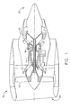
- Figure 1 is a schematic illustration of a gas turbine engine 10 including, in serial flow arrangement, a fan assembly 12, a high-pressure compressor 14, and a combustor 16.
- Engine 10 also includes a high-pressure turbine 18 and a low-pressure turbine 20.
- Engine 10 has an intake side 28 and an exhaust side 30.
- engine 10 is a CF-34 engine commercially available from General Electric Aircraft Engines, Cincinnati, Ohio.
- Airflow from combustor 16 is directed through a turbine nozzle assembly 32 to drive turbines 18 and 20, and turbine 20 drives fan assembly 12.
- Turbine 18 drives high-pressure compressor 14.
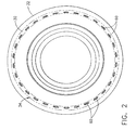
- Figure 2 is a plan view of upstream side 30 of a nozzle support 32 including a gas injector system 34 that may be used with gas turbine engine (shown in Figure 1).
- Figure 3 is a partial plan view of a downstream side 36 of nozzle support 32.
- Figure 4 is a cross-sectional view of nozzle support 32 taken along line 4-4 (shown in Figure 2).
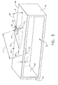
- Figure 5 is a perspective schematic view of a portion of gas injector system 34.
- Nozzle support 32 is annular and is formed unitarily with gas injector system 34.
- Gas injector system 34 includes a plurality of integrally-formed gas injector assemblies 40 that extend around nozzle support 32 for injecting cooling fluid downstream from support 32 at a predetermined injection angle. More specifically, injector assemblies 40 are circumferentially-spaced and each assembly 40 includes a hollow plenum 42 and a unitarily-formed injector 44.
- Plenum 42 is formed by a plenum wall 46 that includes an exterior surface 48 and an interior surface 50. Interior surface 50 defines a cavity 52 within plenum 42.
- Plenum 42 is considered a thin-walled plenum, and plenum wall 46 has a thickness T 1 that is measured between plenum interior and exterior surfaces 50 and 48, respectively. In one embodiment, plenum wall thickness T 1 is less than approximately 0.20 inches.
- Nozzle support upstream side 30 includes a plurality of circumferentially-spaced openings 60 that are in flow communication with plenum cavity 52. Specifically, openings 60 enable cooling fluid supplied from a source (not shown) to enter plenum cavity 52. In the exemplary embodiment, openings 60 are each circular. In an alternative embodiment, openings 60 are non-circular.
- Nozzle support downstream side 36 also includes a plurality of circumferentially-spaced discharge passages 62 that are in flow communication with cavity 52. Discharge passages 62 permit cooling fluid to be discharged from plenum cavity 52. In one exemplary embodiment, each passage 62 has a tear-drop cross-sectional profile. In another embodiment, passage 62 have a non-tear-drop shaped cross-sectional profile.
- Each injector 44 is formed unitarily with plenum 42 and includes a fluid passageway 70 defined therein and extending between an inlet 72 and an outlet 74.
- Passageway 70 extends through plenum wall 46 such that passageway inlet 72 is positioned within plenum cavity 52.
- injector 44 is substantially right cylindrical and passageway 70 is substantially straight therethrough.
- passageway 70 has a circular cross-sectional area, and has a diameter D 1 that is substantially constant between inlet 72 and outlet 74.
- passageway diameter D 1 is variable between inlet 72 and outlet 74.
- passageway 70 has a non-circular cross-sectional area.
- injector passageway 70 extends obliquely through plenum wall 52 and obliquely from plenum exterior surface 48. Accordingly, injector passageway 70 extends obliquely through plenum wall 52, and is obliquely positioned with respect to plenum exterior surface 48. More specifically, injector passageway 70 is positioned at a pre-defined injection angle ⁇ measured between a passageway centerline axis 80 and plenum exterior surface 48. Injection angle ⁇ is greater than about zero degrees. More specifically, in one embodiment, injection angle ⁇ is between approximately fifty and seventy degrees.
- Injection angle ⁇ enables fluid to be discharged from plenum cavity 52 in a direction 82 that is substantially tangential to a direction 84 of ambient fluid flowing past injector 44 and substantially parallel to plenum exterior surface 48. It should be noted that because exterior surface 48 is curved, angle 0 is defined at a specified location with respect to surface 48.
- Injector 44 and passageway 70 have a length L measured between passageway inlet 72 and outlet 74.
- Passageway length L and diameter D 1 are variably selected to facilitate stabilizing fluid flow through passageway 70.
- a ratio of passageway length L to passageway diameter D 1 is at least two to one. More specifically, passageway length L, diameter D 1 , and injection angle ⁇ are variably selected based on cooling fluid requirements in a specific system incorporating gas injector system 34. Passageway length L, and injection angle ⁇ are also dependant on the manufacturing process used to create passageway 70.
- injector length L is selected such that passageway outlet 74 is substantially flush with, or recessed radially inwardly from plenum exterior surface 48. In another embodiment, injector length L is selected such that passageway inlet 74 is substantially flush with, or recessed within plenum interior surface 50.
- cooling fluid supplied to gas injector system 34 is discharged downstream by gas injector assemblies 40.
- gas is discharged from plenums 42 through injectors 44.
- the combination of the injector passageway diameter D 1 , and injector passageway length L facilitate stabilizing fluid flow flowing through injector passageway 70 prior to the cooling fluid being discharged downstream.
- injectors 44 extend obliquely from each plenum 42, cooling fluid discharged from injectors 44 is introduced substantially tangentially to ambient fluid flowing past injectors 44 such that swirling is induced to the cooling fluid as it is discharged from nozzle support 32. Accordingly, gas injector system 34 facilitates providing a substantially circumferential uniform flow downstream from nozzle support 32.
- each unitary gas injector assembly 40 is formed such that plenum 42 and injector 44 are integrally formed. More specifically, in the exemplary embodiment, each assembly 40 is cast, and then each injector passageway 70 is formed therein using a machining process. In an alternative embodiment, a different fabrication process is used to form each unitary gas injector assembly 40. In the exemplary embodiment, each passageway 70 is formed using an electro-discharge machining process. Because gas injector assembly 40 is formed as a unitary body, gas injector system 34 may be installed in engines 10 wherein space and access constraints would prohibit known multi-piece assemblies from being coupled therein.
- the above-described gas injector system provides a cost-effective and highly reliable method for supplying a substantially uniform flow circumferentially downstream in a gas turbine engine.
- the gas injector system includes a plurality of gas injector assemblies that each include a unitarily formed plenum and injector. Accordingly, a gas injector system is provided that facilitates reducing assembly costs while improving reliability in a cost-effective and reliable manner.
- gas injector assemblies Exemplary embodiments of gas injector assemblies are described above in detail.
- the gas injector assemblies are not limited to the specific embodiments described herein, but rather, components of each assembly may be utilized independently and separately from other components described herein.
- Each gas injector assembly component can also be used in combination with other gas injector assembly components.
Landscapes
- Engineering & Computer Science (AREA)
- Mechanical Engineering (AREA)
- General Engineering & Computer Science (AREA)
- Chemical & Material Sciences (AREA)
- Combustion & Propulsion (AREA)
- Turbine Rotor Nozzle Sealing (AREA)
- Nozzles (AREA)
Applications Claiming Priority (2)
| Application Number | Priority Date | Filing Date | Title |
|---|---|---|---|
| US10/424,440 US7052231B2 (en) | 2003-04-28 | 2003-04-28 | Methods and apparatus for injecting fluids in gas turbine engines |
| US424440 | 2003-04-28 |
Publications (2)
| Publication Number | Publication Date |
|---|---|
| EP1473518A2 true EP1473518A2 (de) | 2004-11-03 |
| EP1473518A3 EP1473518A3 (de) | 2012-10-31 |
Family
ID=32990347
Family Applications (1)
| Application Number | Title | Priority Date | Filing Date |
|---|---|---|---|
| EP04252426A Withdrawn EP1473518A3 (de) | 2003-04-28 | 2004-04-27 | Verfahren und Vorrichtung zum Einspritzen von Fluiden für Gasturbinenmotoren |
Country Status (4)
| Country | Link |
|---|---|
| US (1) | US7052231B2 (de) |
| EP (1) | EP1473518A3 (de) |
| JP (1) | JP2004325069A (de) |
| CN (1) | CN100507236C (de) |
Cited By (1)
| Publication number | Priority date | Publication date | Assignee | Title |
|---|---|---|---|---|
| EP3246524A1 (de) * | 2016-05-06 | 2017-11-22 | United Technologies Corporation | Beaufschlagungsverteiler |
Families Citing this family (12)
| Publication number | Priority date | Publication date | Assignee | Title |
|---|---|---|---|---|
| DE102008015207A1 (de) * | 2008-03-20 | 2009-09-24 | Rolls-Royce Deutschland Ltd & Co Kg | Fluid-Injektor-Düse |
| DE102008017844A1 (de) * | 2008-04-08 | 2009-10-15 | Rolls-Royce Deutschland Ltd & Co Kg | Strömungsmaschine mit Fluid-Injektorbaugruppe |
| DE102010027587A1 (de) | 2010-07-19 | 2012-01-19 | Rolls-Royce Deutschland Ltd & Co Kg | Zapfluftauslass im Nebenstromkanal eines Turbofantriebwerks |
| WO2013028163A1 (en) * | 2011-08-22 | 2013-02-28 | Majed Toqan | Tangential and flameless annular combustor for use on gas turbine engines |
| JP6110854B2 (ja) * | 2011-08-22 | 2017-04-05 | トクァン, マジェドTOQAN, Majed | ガス・タービン・エンジンで使用するための予混合燃料空気を用いた接線方向環状燃焼器 |
| WO2013028169A1 (en) * | 2011-08-22 | 2013-02-28 | Majed Toqan | Can-annular combustor with premixed tangential fuel-air nozzles for use on gas turbine engines |
| WO2013028167A2 (en) * | 2011-08-22 | 2013-02-28 | Majed Toqan | Can-annular combustor with staged and tangential fuel-air nozzles for use on gas turbine engines |
| US9377201B2 (en) | 2013-02-08 | 2016-06-28 | Solar Turbines Incorporated | Forged fuel injector stem |
| EP3076084B1 (de) * | 2015-03-30 | 2021-04-28 | Ansaldo Energia Switzerland AG | Kraftstoffinjektorvorrichtung |
| DE102017125051A1 (de) * | 2017-10-26 | 2019-05-02 | Man Diesel & Turbo Se | Strömungsmaschine |
| US11085641B2 (en) * | 2018-11-27 | 2021-08-10 | Honeywell International Inc. | Plug resistant effusion holes for gas turbine engine |
| US11021963B2 (en) * | 2019-05-03 | 2021-06-01 | Raytheon Technologies Corporation | Monolithic body including an internal passage with a generally teardrop shaped cross-sectional geometry |
Family Cites Families (17)
| Publication number | Priority date | Publication date | Assignee | Title |
|---|---|---|---|---|
| GB1350471A (en) * | 1971-05-06 | 1974-04-18 | Secr Defence | Gas turbine engine |
| US4966001A (en) * | 1987-10-23 | 1990-10-30 | General Electric Company | Multiple venturi tube gas fuel injector for catalytic combustor |
| US5001895A (en) * | 1987-12-14 | 1991-03-26 | Sundstrand Corporation | Fuel injector for turbine engines |
| US4891936A (en) * | 1987-12-28 | 1990-01-09 | Sundstrand Corporation | Turbine combustor with tangential fuel injection and bender jets |
| CA2014999C (en) * | 1989-04-24 | 1999-09-07 | Kenneth William Bates | Gas injector |
| DE69305326T2 (de) * | 1992-02-10 | 1997-05-07 | United Technologies Corp | Ejektor für kühlfluid |
| US5402636A (en) * | 1993-12-06 | 1995-04-04 | United Technologies Corporation | Anti-contamination thrust balancing system for gas turbine engines |
| US5727378A (en) * | 1995-08-25 | 1998-03-17 | Great Lakes Helicopters Inc. | Gas turbine engine |
| US5759012A (en) * | 1996-12-13 | 1998-06-02 | Caterpillar Inc. | Turbine disc ingress prevention method and apparatus |
| JPH11132002A (ja) * | 1997-10-28 | 1999-05-18 | Mitsubishi Heavy Ind Ltd | 流量調整プラグ |
| US5988531A (en) * | 1997-11-25 | 1999-11-23 | Solar Turbines | Method of making a fuel injector |
| TW513833B (en) * | 1998-09-09 | 2002-12-11 | Honda Motor Co Ltd | Mounting method of sparking plug cap and sparking plug cap |
| US6224329B1 (en) * | 1999-01-07 | 2001-05-01 | Siemens Westinghouse Power Corporation | Method of cooling a combustion turbine |
| US6234746B1 (en) * | 1999-08-04 | 2001-05-22 | General Electric Co. | Apparatus and methods for cooling rotary components in a turbine |
| US6227798B1 (en) * | 1999-11-30 | 2001-05-08 | General Electric Company | Turbine nozzle segment band cooling |
| US6435816B1 (en) * | 2000-11-03 | 2002-08-20 | General Electric Co. | Gas injector system and its fabrication |
| US6431820B1 (en) * | 2001-02-28 | 2002-08-13 | General Electric Company | Methods and apparatus for cooling gas turbine engine blade tips |
-
2003
- 2003-04-28 US US10/424,440 patent/US7052231B2/en not_active Expired - Fee Related
-
2004
- 2004-04-27 JP JP2004130561A patent/JP2004325069A/ja active Pending
- 2004-04-27 EP EP04252426A patent/EP1473518A3/de not_active Withdrawn
- 2004-04-28 CN CNB2004100367002A patent/CN100507236C/zh not_active Expired - Fee Related
Cited By (2)
| Publication number | Priority date | Publication date | Assignee | Title |
|---|---|---|---|---|
| EP3246524A1 (de) * | 2016-05-06 | 2017-11-22 | United Technologies Corporation | Beaufschlagungsverteiler |
| US10329941B2 (en) | 2016-05-06 | 2019-06-25 | United Technologies Corporation | Impingement manifold |
Also Published As
| Publication number | Publication date |
|---|---|
| JP2004325069A (ja) | 2004-11-18 |
| US20040213664A1 (en) | 2004-10-28 |
| CN100507236C (zh) | 2009-07-01 |
| EP1473518A3 (de) | 2012-10-31 |
| US7052231B2 (en) | 2006-05-30 |
| CN1542267A (zh) | 2004-11-03 |
Similar Documents
| Publication | Publication Date | Title |
|---|---|---|
| EP1489269B1 (de) | Verfahren und Vorrichtung zum Einspritzen von Reinigungsflüssigkeit in Brennkammern | |
| US7052231B2 (en) | Methods and apparatus for injecting fluids in gas turbine engines | |
| US20080276622A1 (en) | Fuel nozzle and method of fabricating the same | |
| CN110006068B (zh) | 用于燃气涡轮发动机燃烧器的燃料喷嘴 | |
| US20180356095A1 (en) | Combustion Section of a Gas Turbine Engine | |
| EP1424525A2 (de) | Verfahren und Vorrichtung zur Reinigung von Brennkammerauskleidungen | |
| EP2489937B1 (de) | Brennkammeranordnung zur Verwendung in einem Gasturbinenmotor und Herstellungsverfahren dafür | |
| EP3039347B1 (de) | Wandanordnung für gasturbinenmotor mit stützschalenkonturregionen | |
| JP2011526976A (ja) | 燃焼器のミキサ及び製造方法 | |
| US20120324898A1 (en) | Combustor assembly for use in a turbine engine and methods of assembling same | |
| EP3077728A2 (de) | Co-swirl-aisrichtung von brennkammerausflussdurchgängen für eine gasturbinenbrennkammer | |
| EP1847779A2 (de) | Optimierte Konfiguration eines Rückstromverbrennungssystems für eine Gasturbine | |
| WO1996019699A1 (en) | LOW NOx FUEL NOZZLE ASSEMBLY | |
| US12504170B2 (en) | Dilution horn pair for a gas turbine engine combustor | |
| US11333360B2 (en) | Fuel injector for a turbomachine | |
| CN110552747A (zh) | 燃烧系统偏转减轻结构 | |
| US20190249875A1 (en) | Liner for a Gas Turbine Engine Combustor | |
| US11262074B2 (en) | HGP component with effusion cooling element having coolant swirling chamber | |
| US20240102653A1 (en) | Dome-deflector joint cooling arrangement | |
| US7360364B2 (en) | Method and apparatus for assembling gas turbine engine combustors | |
| CA2472541C (en) | Methods and apparatus for supplying feed air to turbine combustors | |
| JP2022159047A (ja) | 後流エナジャイザを備えた燃焼器 | |
| CN117146296A (zh) | 具有稀释冷却衬里的燃烧器 |
Legal Events
| Date | Code | Title | Description |
|---|---|---|---|
| PUAI | Public reference made under article 153(3) epc to a published international application that has entered the european phase |
Free format text: ORIGINAL CODE: 0009012 |
|
| AK | Designated contracting states |
Kind code of ref document: A2 Designated state(s): AT BE BG CH CY CZ DE DK EE ES FI FR GB GR HU IE IT LI LU MC NL PL PT RO SE SI SK TR |
|
| AX | Request for extension of the european patent |
Extension state: AL HR LT LV MK |
|
| PUAL | Search report despatched |
Free format text: ORIGINAL CODE: 0009013 |
|
| AK | Designated contracting states |
Kind code of ref document: A3 Designated state(s): AT BE BG CH CY CZ DE DK EE ES FI FR GB GR HU IE IT LI LU MC NL PL PT RO SE SI SK TR |
|
| AX | Request for extension of the european patent |
Extension state: AL HR LT LV MK |
|
| RIC1 | Information provided on ipc code assigned before grant |
Ipc: F23R 3/04 20060101AFI20120926BHEP Ipc: F01D 9/02 20060101ALI20120926BHEP Ipc: F01D 11/24 20060101ALI20120926BHEP |
|
| 17P | Request for examination filed |
Effective date: 20130502 |
|
| AKX | Designation fees paid |
Designated state(s): DE FR GB |
|
| 17Q | First examination report despatched |
Effective date: 20130612 |
|
| GRAP | Despatch of communication of intention to grant a patent |
Free format text: ORIGINAL CODE: EPIDOSNIGR1 |
|
| INTG | Intention to grant announced |
Effective date: 20151208 |
|
| STAA | Information on the status of an ep patent application or granted ep patent |
Free format text: STATUS: THE APPLICATION IS DEEMED TO BE WITHDRAWN |
|
| 18D | Application deemed to be withdrawn |
Effective date: 20160419 |