EP1473516A1 - Vorrichtung und Verfahren zur Fehlerüberwachung einer Auswerteschaltung - Google Patents
Vorrichtung und Verfahren zur Fehlerüberwachung einer Auswerteschaltung Download PDFInfo
- Publication number
- EP1473516A1 EP1473516A1 EP04009373A EP04009373A EP1473516A1 EP 1473516 A1 EP1473516 A1 EP 1473516A1 EP 04009373 A EP04009373 A EP 04009373A EP 04009373 A EP04009373 A EP 04009373A EP 1473516 A1 EP1473516 A1 EP 1473516A1
- Authority
- EP
- European Patent Office
- Prior art keywords
- evaluation circuit
- circuit
- sensor
- evaluation
- monitoring
- Prior art date
- Legal status (The legal status is an assumption and is not a legal conclusion. Google has not performed a legal analysis and makes no representation as to the accuracy of the status listed.)
- Withdrawn
Links
- 238000011156 evaluation Methods 0.000 title claims abstract description 48
- 238000000034 method Methods 0.000 title claims abstract description 13
- 238000012544 monitoring process Methods 0.000 claims abstract description 13
- 238000005259 measurement Methods 0.000 claims description 6
- 239000007789 gas Substances 0.000 description 4
- 230000007547 defect Effects 0.000 description 2
- 230000001276 controlling effect Effects 0.000 description 1
- 239000000446 fuel Substances 0.000 description 1
- 238000004519 manufacturing process Methods 0.000 description 1
- 238000012545 processing Methods 0.000 description 1
- 230000001105 regulatory effect Effects 0.000 description 1
- 238000012552 review Methods 0.000 description 1
Images
Classifications
-
- F—MECHANICAL ENGINEERING; LIGHTING; HEATING; WEAPONS; BLASTING
- F23—COMBUSTION APPARATUS; COMBUSTION PROCESSES
- F23N—REGULATING OR CONTROLLING COMBUSTION
- F23N5/00—Systems for controlling combustion
- F23N5/24—Preventing development of abnormal or undesired conditions, i.e. safety arrangements
- F23N5/242—Preventing development of abnormal or undesired conditions, i.e. safety arrangements using electronic means
-
- F—MECHANICAL ENGINEERING; LIGHTING; HEATING; WEAPONS; BLASTING
- F23—COMBUSTION APPARATUS; COMBUSTION PROCESSES
- F23N—REGULATING OR CONTROLLING COMBUSTION
- F23N5/00—Systems for controlling combustion
- F23N5/003—Systems for controlling combustion using detectors sensitive to combustion gas properties
-
- F—MECHANICAL ENGINEERING; LIGHTING; HEATING; WEAPONS; BLASTING
- F23—COMBUSTION APPARATUS; COMBUSTION PROCESSES
- F23N—REGULATING OR CONTROLLING COMBUSTION
- F23N2223/00—Signal processing; Details thereof
- F23N2223/16—Measuring bridge
-
- F—MECHANICAL ENGINEERING; LIGHTING; HEATING; WEAPONS; BLASTING
- F23—COMBUSTION APPARATUS; COMBUSTION PROCESSES
- F23N—REGULATING OR CONTROLLING COMBUSTION
- F23N2223/00—Signal processing; Details thereof
- F23N2223/30—Switches
-
- F—MECHANICAL ENGINEERING; LIGHTING; HEATING; WEAPONS; BLASTING
- F23—COMBUSTION APPARATUS; COMBUSTION PROCESSES
- F23N—REGULATING OR CONTROLLING COMBUSTION
- F23N2225/00—Measuring
- F23N2225/26—Measuring humidity
- F23N2225/30—Measuring humidity measuring lambda
-
- F—MECHANICAL ENGINEERING; LIGHTING; HEATING; WEAPONS; BLASTING
- F23—COMBUSTION APPARATUS; COMBUSTION PROCESSES
- F23N—REGULATING OR CONTROLLING COMBUSTION
- F23N2227/00—Ignition or checking
- F23N2227/12—Burner simulation or checking
- F23N2227/16—Checking components, e.g. electronic
-
- F—MECHANICAL ENGINEERING; LIGHTING; HEATING; WEAPONS; BLASTING
- F23—COMBUSTION APPARATUS; COMBUSTION PROCESSES
- F23N—REGULATING OR CONTROLLING COMBUSTION
- F23N2231/00—Fail safe
- F23N2231/10—Fail safe for component failures
Definitions
- the invention relates to a device and a method for fault monitoring an evaluation circuit.
- Electronic evaluation circuits are often used to determine the output signal a measuring sensor into a signal for controlling a device or for displaying a Operating state to use. Some errors can occur here.
- DE 101 33 525 describes a method for checking the functionality of a Sensor known. However, not only can the sensor have an error, it can also the evaluation circuit may be faulty. As a result of a defect in the evaluation circuits a device can be incorrectly controlled or regulated. As a result, it can lead to safety-relevant situations.
- the invention is therefore based on the problem of an error in the evaluation circuit to recognize independently and to initiate countermeasures accordingly.
- this is achieved by a method according to the features of claim 1 reached.
- a is used instead of the measuring sensor Reference resistor connected to the evaluation circuit and the generated thereby Signal compared with a predetermined reference value.
- this check can be done before or after actual measurement done with the sensor.
- the features of claim 4 additionally protect that in the presence of a Measurement signal that differs significantly from the specified reference signal, a signal for Existence of an error is issued, so appropriate countermeasures can be initiated.
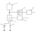
- the figure shows a switching device 1, which on the one hand has a constant current source 7 or alternatively connected to a constant voltage source and on the other hand switchable with a sensor 2 and a measuring resistor 3, each with the mass are connected, connected.
- the sensor 2 and the Measuring resistor 3 can also be connected to another, fixed potential.
- the switching device 1 with an evaluation circuit 4 to which a circuit 6 connects, connected.
- the switching device 1 is a switching device 5 connected.
- the switching device 1 to the sensor 2 connected so that a direct connection of the sensor 2 with the Evaluation device 4 is present.
- Delivers according to the measurand to be measured the sensor 2 receives a signal which is forwarded to the evaluation circuit 4.
- the Evaluation circuit 4 follows a circuit 6, which are used for this purpose, for example can regulate the device in which the evaluation circuit is located, an output signal to generate for the consumer or the like.
- the switching device 5 switches the Switching device 1, whereby the reference resistor 3 with the evaluation circuit 4th is connected. A corresponding output signal is in the evaluation circuit 4 generated, which is initiated in the circuit 6. There the signal with a predetermined reference value compared. If the evaluation circuit 4 is OK, then the measured signal corresponds to the specified reference value. Owing to Manufacturing tolerances can only be expected, however, that the output signal of the Evaluation circuit 4 approximately corresponds to the predetermined reference value. About Or falls below the output signal of the evaluation circuit 4 a certain Bandwidth, this is an indication that there is an error.
- Such a circuit including its monitoring in a heater with a sensor for detecting the gas concentration is used.
- Such devices adjust the fuel gas-air ratio by measuring the in the exhaust gas contained gases. If there is an error, it is for security reasons necessary that a countermeasure be initiated. Is with the signal that is Processing the reference resistance results in an implausible value, so it can on the one hand, there is a defect in the device or the evaluation electronics. To one To avoid endangering the consumer, the device is switched off.
Landscapes
- Engineering & Computer Science (AREA)
- Chemical & Material Sciences (AREA)
- Combustion & Propulsion (AREA)
- Mechanical Engineering (AREA)
- General Engineering & Computer Science (AREA)
- Investigating Or Analyzing Materials By The Use Of Electric Means (AREA)
- Investigating Or Analyzing Materials By The Use Of Fluid Adsorption Or Reactions (AREA)
Abstract
Description
Claims (7)
- Verfahren zur Überwachung einer Auswerteschaltung (4), an welche ein Sensor (2) angeschlossen ist, dadurch gekennzeichnet, dass eine Umschalteinrichtung (1) die Auswerteschaltung (4) entweder mit dem Sensor (2) oder mindestens einem Referenzwiderstand (3) verbindet, zur Überprüfung der Funktionstüchtigkeit der Auswerteschaltung (4) die Auswerteschaltung (4) mit mindestens einem Referenzwiderstand (3) verbunden wird, und eine Schaltung (6) am Ausgang der Auswerteschaltung (4) das Ausgangssignal der Auswerteschaltung (4) mit mindestens einem vorgebenden Referenzwert vergleicht.
- Verfahren zur Überwachung einer Auswerteschaltung (4) gemäß Anspruch 1, dadurch gekennzeichnet, dass die Überprüfung der Funktionstüchtigkeit der Auswerteschaltung (4) vor oder nach der Messung mit dem Sensor (2) geschieht.
- Verfahren zur Überwachung einer Auswerteschaltung (4) gemäß Anspruch 1 oder 2, dadurch gekennzeichnet, dass die Überprüfung der Funktionstüchtigkeit der Auswerteschaltung (4) zyklisch während der Messung mit dem Sensor (2) geschieht.
- Verfahren zur Überwachung einer Auswerteschaltung (4) gemäß einem der Ansprüche 1 bis 3, dadurch gekennzeichnet, dass die Schaltung (6), wenn das Meßsignal vom Referenzwert um einen vorgegebenen Wert abweicht, ein Signal, das auf das Vorliegen eines Fehlers hinweist, ausgibt.
- Verfahren zur Überwachung einer Auswerteschaltung (4) gemäß einem der Ansprüche 1 bis 4, dadurch gekennzeichnet, dass der Sensor (2) eine Gaskonzentration erfasst.
- Verfahren zur Überwachung einer Auswerteschaltung (4) gemäß Anspruch 5, dadurch gekennzeichnet, dass der Sensor (2) in der Abgasleitung eines Heizgerätes angeordnet ist.
- Schaltung zur Überwachung einer Auswerteschaltung (4), an welche ein Sensor (2) angeschlossen ist, dadurch gekennzeichnet, dass eine Umschalteinrichtung (1) zwischen der Auswerteschaltung (4) und dem Sensor (2) vorgesehen ist, dass die Umschalteinrichtung (1) zwischen dem Anschluss zu dem Sensor (2) und mindestens einem Referenzwiderstand (3) umschalten kann, so dass die Auswerteschaltung (4) mit dem mindestens einen Referenzwiderstand (3) verbindbar ist, und eine Schaltung (6) am Ausgang der Auswerteschaltung (4) zur Überprüfung der Funktionstüchtigkeit der Auswerteschaltung (4) das Ausgangssignal der Auswerteschaltung (4) bei Verbindung des mindestens einen Meßwiderstandes (3) mit der Auswerteelektronik (4) mit einem vorgebenden Referenzwert vergleicht.
Applications Claiming Priority (2)
| Application Number | Priority Date | Filing Date | Title |
|---|---|---|---|
| AT6352003 | 2003-04-28 | ||
| AT0063503A AT500257A2 (de) | 2003-04-28 | 2003-04-28 | Verfahren zur fehlerüberwachung einer auswerteschaltung |
Publications (1)
| Publication Number | Publication Date |
|---|---|
| EP1473516A1 true EP1473516A1 (de) | 2004-11-03 |
Family
ID=32968006
Family Applications (1)
| Application Number | Title | Priority Date | Filing Date |
|---|---|---|---|
| EP04009373A Withdrawn EP1473516A1 (de) | 2003-04-28 | 2004-04-21 | Vorrichtung und Verfahren zur Fehlerüberwachung einer Auswerteschaltung |
Country Status (3)
| Country | Link |
|---|---|
| EP (1) | EP1473516A1 (de) |
| AT (1) | AT500257A2 (de) |
| DE (1) | DE102004019265A1 (de) |
Cited By (1)
| Publication number | Priority date | Publication date | Assignee | Title |
|---|---|---|---|---|
| WO2007087940A1 (de) * | 2006-01-31 | 2007-08-09 | BSH Bosch und Siemens Hausgeräte GmbH | Verfahren zum betreiben eines haushaltsgeräts und schaltung für das haushaltsgerät |
Citations (6)
| Publication number | Priority date | Publication date | Assignee | Title |
|---|---|---|---|---|
| US4127887A (en) * | 1976-09-08 | 1978-11-28 | Hitachi, Ltd. | Safety test circuit for combustion control apparatus |
| US4403942A (en) * | 1980-11-18 | 1983-09-13 | Carrier Corporation | Self-checking safety switch control circuit |
| EP0655583A1 (de) * | 1993-11-29 | 1995-05-31 | ABBPATENT GmbH | Verfahren zur Regelung und Überwachung |
| DE19956426C1 (de) * | 1999-11-24 | 2001-05-03 | Honeywell Bv | Vorrichtung zur Überwachung der Wassertemperatur |
| EP1199519A2 (de) * | 2000-10-19 | 2002-04-24 | RB Controls Co., Ltd. | Verbrennungssteuervorrichtung |
| DE10133525A1 (de) * | 2001-07-11 | 2003-01-30 | Bosch Gmbh Robert | Sensor mit Selbst-Test-Funktion |
-
2003
- 2003-04-28 AT AT0063503A patent/AT500257A2/de not_active Application Discontinuation
-
2004
- 2004-04-21 DE DE102004019265A patent/DE102004019265A1/de not_active Withdrawn
- 2004-04-21 EP EP04009373A patent/EP1473516A1/de not_active Withdrawn
Patent Citations (6)
| Publication number | Priority date | Publication date | Assignee | Title |
|---|---|---|---|---|
| US4127887A (en) * | 1976-09-08 | 1978-11-28 | Hitachi, Ltd. | Safety test circuit for combustion control apparatus |
| US4403942A (en) * | 1980-11-18 | 1983-09-13 | Carrier Corporation | Self-checking safety switch control circuit |
| EP0655583A1 (de) * | 1993-11-29 | 1995-05-31 | ABBPATENT GmbH | Verfahren zur Regelung und Überwachung |
| DE19956426C1 (de) * | 1999-11-24 | 2001-05-03 | Honeywell Bv | Vorrichtung zur Überwachung der Wassertemperatur |
| EP1199519A2 (de) * | 2000-10-19 | 2002-04-24 | RB Controls Co., Ltd. | Verbrennungssteuervorrichtung |
| DE10133525A1 (de) * | 2001-07-11 | 2003-01-30 | Bosch Gmbh Robert | Sensor mit Selbst-Test-Funktion |
Cited By (1)
| Publication number | Priority date | Publication date | Assignee | Title |
|---|---|---|---|---|
| WO2007087940A1 (de) * | 2006-01-31 | 2007-08-09 | BSH Bosch und Siemens Hausgeräte GmbH | Verfahren zum betreiben eines haushaltsgeräts und schaltung für das haushaltsgerät |
Also Published As
| Publication number | Publication date |
|---|---|
| AT500257A2 (de) | 2005-11-15 |
| DE102004019265A1 (de) | 2004-11-18 |
Similar Documents
| Publication | Publication Date | Title |
|---|---|---|
| EP0925512B1 (de) | Verfahren und schaltung zur funktionsüberwachung einer sensorbrücke | |
| DE69226277T2 (de) | Fail-safe fuehlerschaltung | |
| EP1058093B1 (de) | Verfahren und Schaltungsanordnung zur Spannungsversorgung und Funktionsüberwachung zumindest eines Messwertumformers | |
| DE102017126754B4 (de) | Eingangsschaltung zum fehlersicheren Einlesen eines analogen Eingangssignals | |
| EP2324291A2 (de) | Sicherungssystem in und verfahren zum betrieb einer verbrennungsanlage | |
| DE102008003799A1 (de) | Überwachungsvorrichtung für ein Meldesystem, Meldesystem und Verfahren zur Überwachung des Meldesystems | |
| EP3688874B1 (de) | Schaltkreis zur überprüfung einer analogen eingangsschaltung eines a/d-wandlers | |
| DE102013111888B4 (de) | Sicherheitsvorrichtung zum mehrkanaligen Verarbeiten eines analogen Eingangssignals | |
| WO2014170051A1 (de) | Messumformer zur prozessinstrumentierung und verfahren zu dessen diagnose | |
| WO2009138398A1 (de) | Sensoreinrichtung und fehlererkennungsverfahren für elektronische schaltungen in kraftfahrzeugen | |
| EP2169645B1 (de) | Prüfung der Meldelinien einer Gefahrenmeldeanlage | |
| WO2001060663A1 (de) | Verfahren und vorrichtung zum überprüfen einer sensoreinrichtung, insbesondere einer in einem fahrzeuginsassen-schutzsystem enthaltenen beschleunigungssensoreinrichtung | |
| DE102018114781A1 (de) | Schaltungsanordnung zum Schalten einer elektrischen Last und Verfahren zur Überprüfung eines Status eines Sicherheitsausgangs einer Schaltungsanordnung | |
| DE102004019265A1 (de) | Vorrichtung und Verfahren zur Fehlerüberwachung einer Auswerteschaltung | |
| DE102008048929B4 (de) | Prüfung der Meldelinien einer Gefahrenmeldeanlage | |
| DE4210848A1 (de) | Sicherheitseinrichtung | |
| EP0417392B1 (de) | Ausgangsschaltung für ein Potentiometer | |
| EP1538453A1 (de) | Vorrichtung und Verfahren zur Fehlerdiagnose an digitalen Ausgängen einer Steuerbaugruppe | |
| DE102020121076B3 (de) | Stromschnittstelle zur Erzeugung eines analogen Ausgangsstroms von 4 bis 20 mA sowie Verfahren zum Betreiben einer solchen Stromschnittstelle | |
| WO2014161676A1 (de) | Messumformer zur prozessinstrumentierung und verfahren zur überwachung des zustands dessen sensors | |
| DE102021113552A1 (de) | Feldgerät mit Schutzschaltung, Verfahren zur Sicherstellung eines eigensicheren Betriebs eines Feldgeräts sowie Computerprogrammcode | |
| DE19722549A1 (de) | Elektrische Meßeinrichtung bzw. elektrisches Meßverfahren zur Erzeugung eines elektrischen Signals | |
| DE102021203550A1 (de) | Beleuchtungsvorrichtung, Notausschalter und Betriebsverfahren | |
| DE3919960A1 (de) | Schaltungsanordnung zum ueberwachen einer binaeren signale uebertragenden leitung auf kurzschluss und unterbrechung | |
| EP1894028B1 (de) | Verfahren zur erkennung von bauteilefehlern einer analogen signalverarbeitungsschaltung für einen messumformer |
Legal Events
| Date | Code | Title | Description |
|---|---|---|---|
| PUAI | Public reference made under article 153(3) epc to a published international application that has entered the european phase |
Free format text: ORIGINAL CODE: 0009012 |
|
| AK | Designated contracting states |
Kind code of ref document: A1 Designated state(s): AT BE BG CH CY CZ DE DK EE ES FI FR GB GR HU IE IT LI LU MC NL PL PT RO SE SI SK TR |
|
| AX | Request for extension of the european patent |
Extension state: AL HR LT LV MK |
|
| 17P | Request for examination filed |
Effective date: 20050412 |
|
| AKX | Designation fees paid |
Designated state(s): AT BE BG CH CY CZ DE DK EE ES FI FR GB GR HU IE IT LI LU MC NL PL PT RO SE SI SK TR |
|
| 17Q | First examination report despatched |
Effective date: 20060725 |
|
| STAA | Information on the status of an ep patent application or granted ep patent |
Free format text: STATUS: THE APPLICATION IS DEEMED TO BE WITHDRAWN |
|
| 18D | Application deemed to be withdrawn |
Effective date: 20061205 |