EP1473200A2 - Airbag module - Google Patents
Airbag module Download PDFInfo
- Publication number
- EP1473200A2 EP1473200A2 EP04009611A EP04009611A EP1473200A2 EP 1473200 A2 EP1473200 A2 EP 1473200A2 EP 04009611 A EP04009611 A EP 04009611A EP 04009611 A EP04009611 A EP 04009611A EP 1473200 A2 EP1473200 A2 EP 1473200A2
- Authority
- EP
- European Patent Office
- Prior art keywords
- housing
- gas generator
- airbag module
- module according
- igniter
- Prior art date
- Legal status (The legal status is an assumption and is not a legal conclusion. Google has not performed a legal analysis and makes no representation as to the accuracy of the status listed.)
- Granted
Links
Images


Classifications
-
- B—PERFORMING OPERATIONS; TRANSPORTING
- B60—VEHICLES IN GENERAL
- B60R—VEHICLES, VEHICLE FITTINGS, OR VEHICLE PARTS, NOT OTHERWISE PROVIDED FOR
- B60R21/00—Arrangements or fittings on vehicles for protecting or preventing injuries to occupants or pedestrians in case of accidents or other traffic risks
- B60R21/02—Occupant safety arrangements or fittings, e.g. crash pads
- B60R21/16—Inflatable occupant restraints or confinements designed to inflate upon impact or impending impact, e.g. air bags
- B60R21/20—Arrangements for storing inflatable members in their non-use or deflated condition; Arrangement or mounting of air bag modules or components
- B60R21/217—Inflation fluid source retainers, e.g. reaction canisters; Connection of bags, covers, diffusers or inflation fluid sources therewith or together
- B60R21/2171—Inflation fluid source retainers, e.g. reaction canisters; Connection of bags, covers, diffusers or inflation fluid sources therewith or together specially adapted for elongated cylindrical or bottle-like inflators with a symmetry axis perpendicular to the main direction of bag deployment, e.g. extruded reaction canisters
-
- B—PERFORMING OPERATIONS; TRANSPORTING
- B60—VEHICLES IN GENERAL
- B60R—VEHICLES, VEHICLE FITTINGS, OR VEHICLE PARTS, NOT OTHERWISE PROVIDED FOR
- B60R21/00—Arrangements or fittings on vehicles for protecting or preventing injuries to occupants or pedestrians in case of accidents or other traffic risks
- B60R21/02—Occupant safety arrangements or fittings, e.g. crash pads
- B60R21/16—Inflatable occupant restraints or confinements designed to inflate upon impact or impending impact, e.g. air bags
- B60R21/26—Inflatable occupant restraints or confinements designed to inflate upon impact or impending impact, e.g. air bags characterised by the inflation fluid source or means to control inflation fluid flow
- B60R21/264—Inflatable occupant restraints or confinements designed to inflate upon impact or impending impact, e.g. air bags characterised by the inflation fluid source or means to control inflation fluid flow using instantaneous generation of gas, e.g. pyrotechnic
- B60R21/2644—Inflatable occupant restraints or confinements designed to inflate upon impact or impending impact, e.g. air bags characterised by the inflation fluid source or means to control inflation fluid flow using instantaneous generation of gas, e.g. pyrotechnic using only solid reacting substances, e.g. pellets, powder
-
- B—PERFORMING OPERATIONS; TRANSPORTING
- B60—VEHICLES IN GENERAL
- B60R—VEHICLES, VEHICLE FITTINGS, OR VEHICLE PARTS, NOT OTHERWISE PROVIDED FOR
- B60R21/00—Arrangements or fittings on vehicles for protecting or preventing injuries to occupants or pedestrians in case of accidents or other traffic risks
- B60R21/02—Occupant safety arrangements or fittings, e.g. crash pads
- B60R21/16—Inflatable occupant restraints or confinements designed to inflate upon impact or impending impact, e.g. air bags
- B60R21/26—Inflatable occupant restraints or confinements designed to inflate upon impact or impending impact, e.g. air bags characterised by the inflation fluid source or means to control inflation fluid flow
- B60R21/263—Inflatable occupant restraints or confinements designed to inflate upon impact or impending impact, e.g. air bags characterised by the inflation fluid source or means to control inflation fluid flow using a variable source, e.g. plural stage or controlled output
- B60R2021/2633—Inflatable occupant restraints or confinements designed to inflate upon impact or impending impact, e.g. air bags characterised by the inflation fluid source or means to control inflation fluid flow using a variable source, e.g. plural stage or controlled output with a plurality of inflation levels
-
- B—PERFORMING OPERATIONS; TRANSPORTING
- B60—VEHICLES IN GENERAL
- B60R—VEHICLES, VEHICLE FITTINGS, OR VEHICLE PARTS, NOT OTHERWISE PROVIDED FOR
- B60R21/00—Arrangements or fittings on vehicles for protecting or preventing injuries to occupants or pedestrians in case of accidents or other traffic risks
- B60R21/02—Occupant safety arrangements or fittings, e.g. crash pads
- B60R21/16—Inflatable occupant restraints or confinements designed to inflate upon impact or impending impact, e.g. air bags
- B60R21/26—Inflatable occupant restraints or confinements designed to inflate upon impact or impending impact, e.g. air bags characterised by the inflation fluid source or means to control inflation fluid flow
- B60R21/264—Inflatable occupant restraints or confinements designed to inflate upon impact or impending impact, e.g. air bags characterised by the inflation fluid source or means to control inflation fluid flow using instantaneous generation of gas, e.g. pyrotechnic
- B60R21/2644—Inflatable occupant restraints or confinements designed to inflate upon impact or impending impact, e.g. air bags characterised by the inflation fluid source or means to control inflation fluid flow using instantaneous generation of gas, e.g. pyrotechnic using only solid reacting substances, e.g. pellets, powder
- B60R2021/2648—Inflatable occupant restraints or confinements designed to inflate upon impact or impending impact, e.g. air bags characterised by the inflation fluid source or means to control inflation fluid flow using instantaneous generation of gas, e.g. pyrotechnic using only solid reacting substances, e.g. pellets, powder comprising a plurality of combustion chambers or sub-chambers
Definitions
- the invention relates to an airbag module with a generally cylindrical Gas generator, at least one igniter and a housing on which the gas generator is attached.
- the invention relates in particular to an airbag module for a passenger of a vehicle.
- Such an airbag module should require minimal installation space and one light weight. It should also have a simple structure to to be able to be produced at low cost. After all, minor Leakage losses occur when inflating the gas bag to one if possible to achieve high efficiency.
- the object of the invention is an inexpensive gas bag module to create the type mentioned above, which meets the requirements Fulfills.
- the beginning of a gas bag module mentioned type provided that the igniter radially from the gas generator extends and is attached to the housing and that an airbag is provided, which is clamped between the gas generator and the housing.
- the Invention is based on the basic idea of fastening the gas generator on Housing to use the igniter. This results in a simple construction, as on the otherwise usual mounting plates etc. can be dispensed with; to attach the gas generator in the housing existing component used anyway. This needs little Effort to be designed so that it is suitable for attachment. To the others have very low leakage losses since the igniter is immediate can be connected from outside the housing; there are not any Passages for cables, etc.
- the gas generator is integrated into the module can be that the structural strength of the gas generator is a relevant Part of the mechanical component strength of the entire gas bag module becomes.
- the otherwise usual inserts are dispensed with be used to attach the gas bag to the housing. So it turns out a particularly simple structure with a small number of components.
- the detonator can have a holding geometry be provided by means of which it is locked on the housing, so that the Gas generator is firmly connected to the housing.
- a holding geometry can in particular an external thread can be used, onto which a nut is screwed which is outside the housing and in this way the Gas generator firmly connected to the housing. It is also possible that as a holding geometry a groove is used in which a retaining ring is inserted.
- FIGS. 1 to 3 show an airbag module that has a housing 10 having.
- the housing 10 serves to accommodate a folded gas bag 12 and a gas generator 14.
- the gas generator which here is a cylindrical tubular gas generator After activation, a compressed gas can be provided by means of which the gas bag 12 can be deployed in a manner known per se.
- the Housing 10 can consist of sheet metal and serves on the one hand as a receptacle for the other components of the gas bag module and on the other hand enables attachment of the gas bag module in a vehicle.
- the gas generator 14 is provided with two igniters 16, which are related to the The central axis of the gas generator 14 are arranged radially.
- everyone is the detonator assigned to its own gas-generating charge; it is the gas generator is a 2-stage gas generator. But it can also be a gas generator more than 2 levels can be used.
- the housing 10 is provided with two openings 18 through which the outside of the gas generator 14 sections of the igniter 16 from the Extend the housing. These sections outside the housing the igniter 16 are each provided with a holding geometry 18, which in the the embodiment shown in Figures 1 to 3 is an external thread. On the External threads can each be screwed on a nut 22.
- the gas generator 14 is inside the gas bag 12 arranged.
- the gas bag 12 is when the gas generator in the housing 10 is arranged and the nuts 22 are tightened between the gas generator 14 and the housing 10 is clamped so that it is firmly fixed there.
- the igniters 16 are on their from the gas generator 14 facing away, free end, each with a plug connection 24, about the two gas generators are connected to an ignition device can. It can be seen that there is no separate passage for a line or Similar is required in the interior of the gas bag module. In this way the gas tightness is particularly high.
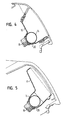
- FIG. 4 schematically shows an airbag module according to a first variant shown.
- the housing 10 is here with a trough-shaped receiving section 26 executed for the gas generator 14. Since the gas generator 14 covers a large area can support the inside of the housing 10, the gas generator carries crucial to the structural strength of the entire housing 10.
- a second variant is shown in FIG.
- the difference to the first Variant is that the trough-shaped receiving section 26 is made deeper is.
Abstract
Description
Die Erfindung betrifft ein Gassack-Modul mit einem allgemein zylindrischen Gasgenerator, mindestens einem Zünder und einem Gehäuse, an dem der Gasgenerator befestigt ist. Die Erfindung betrifft insbesondere ein Gassack-Modul für einen Beifahrer eines Fahrzeugs.The invention relates to an airbag module with a generally cylindrical Gas generator, at least one igniter and a housing on which the gas generator is attached. The invention relates in particular to an airbag module for a passenger of a vehicle.
Ein solches Gassack-Modul soll einen minimalen Bauraum erfordern und ein geringes Gewicht aufweisen. Außerdem soll es einen einfachen Aufbau haben, um mit geringen Kosten hergestellt werden zu können. Schließlich sollen geringe Leckage-Verluste beim Aufblasen des Gassacks auftreten, um einen möglichst hohen Wirkungsgrad zu erzielen.Such an airbag module should require minimal installation space and one light weight. It should also have a simple structure to to be able to be produced at low cost. After all, minor Leakage losses occur when inflating the gas bag to one if possible to achieve high efficiency.
Die Aufgabe der Erfindung besteht darin, ein kostengünstiges Gassack-Modul der eingangs genannten Art zu schaffen, welches die genannten Anforderungen erfüllt.The object of the invention is an inexpensive gas bag module to create the type mentioned above, which meets the requirements Fulfills.
Zu diesem Zweck ist erfindungsgemäß bei einem Gassack-Modul der eingangs genannten Art vorgesehen, daß der Zünder sich radial aus dem Gasgenerator herauserstreckt und am Gehäuse befestigt ist und daß ein Gassack vorgesehen ist, der zwischen dem Gasgenerator und dem Gehäuse eingeklemmt ist. Die Erfindung beruht auf dem Grundgedanken, zur Befestigung des Gasgenerators am Gehäuse den Zünder zu verwenden. Auf diese Weise ergibt sich zum einen ein einfacher Aufbau, da auf die ansonsten üblichen Befestigungsbleche etc. verzichtet werden kann; zur Befestigung des Gasgenerators im Gehäuse wird ein ohnehin vorhandenes Bauteil verwendet. Dieses braucht nur mit geringem Aufwand so ausgestaltet zu werden, daß es zur Befestigung geeignet ist. Zum anderen ergeben sich sehr geringe Leckage-Verluste, da der Zünder unmittelbar von außerhalb des Gehäuses angeschlossen werden kann; es sind keine Durchlässe für Kabel etc. erforderlich, die im Stand der Technik für einen vollständig innerhalb des Gehäuses angeordneten Zünder notwendig waren. Ein weiterer Vorteil besteht darin, daß der Gasgenerator so in das Modul integriert werden kann, daß die Strukturfestigkeit des Gasgenerators ein relevanter Bestandteil der mechanischen Bauteilfestigkeit des gesamten Gassack-Moduls wird. Schließlich kann, da der Gassack direkt vom Gasgenerator am Gehäuse festgespannt wird, auf die ansonsten üblichen Einlegeteile verzichtet werden, die zur Befestigung des Gassacks am Gehäuse verwendet werden. Es ergibt sich also ein besonders einfacher Aufbau mit einer geringen Anzahl von Bauteilen.For this purpose, according to the invention, the beginning of a gas bag module mentioned type provided that the igniter radially from the gas generator extends and is attached to the housing and that an airbag is provided, which is clamped between the gas generator and the housing. The Invention is based on the basic idea of fastening the gas generator on Housing to use the igniter. This results in a simple construction, as on the otherwise usual mounting plates etc. can be dispensed with; to attach the gas generator in the housing existing component used anyway. This needs little Effort to be designed so that it is suitable for attachment. To the others have very low leakage losses since the igniter is immediate can be connected from outside the housing; there are not any Passages for cables, etc. required in the prior art for a Igniters placed entirely within the housing were necessary. On Another advantage is that the gas generator is integrated into the module can be that the structural strength of the gas generator is a relevant Part of the mechanical component strength of the entire gas bag module becomes. Finally, since the gas bag can be directly from the gas generator on the housing is clamped, the otherwise usual inserts are dispensed with be used to attach the gas bag to the housing. So it turns out a particularly simple structure with a small number of components.
Zur Befestigung des Zünders am Gehäuse kann der Zünder mit einer Halte-Geometrie versehen sein, mittels der er am Gehäuse arretiert ist, so daß der Gasgenerator fest mit dem Gehäuse verbunden ist. Als Halte-Geometrie kann insbesondere ein Außengewinde verwendet werden, auf das eine Mutter aufgeschraubt wird, die außerhalb des Gehäuses liegt und auf diese Weise den Gasgenerator fest mit dem Gehäuse verbindet. Es ist auch möglich, daß als Halte-Geometrie eine Nut verwendet wird, in die ein Haltering eingesetzt wird.To attach the detonator to the housing, the detonator can have a holding geometry be provided by means of which it is locked on the housing, so that the Gas generator is firmly connected to the housing. As a holding geometry can in particular an external thread can be used, onto which a nut is screwed which is outside the housing and in this way the Gas generator firmly connected to the housing. It is also possible that as a holding geometry a groove is used in which a retaining ring is inserted.
Vorteilhafte Ausgestaltungen der Erfindung ergeben sich aus den Unteransprüchen.Advantageous embodiments of the invention result from the subclaims.
Die Erfindung wird nachfolgend anhand einer bevorzugten Ausführungsform beschrieben, die in den beigefügten Zeichnungen dargestellt ist. In diesen zeigen:
- Figur 1 eine perspektivische Explosionsansicht eines erfindungsgemäßen Gassack-Moduls;
- Figur 2 eine perspektivische Unteransicht des montierten Gassack-Moduls;
- Figur 3 eine Schnittansicht durch das erfindungsgemäße Gassack-Modul;
- Figur 4 in einem schematischen Schnitt ein Gassack-Modul gemäß einer ersten Variante; und
- Figur 5 in einem schematischen Schnitt ein Gassack-Modul gemäß einer zweiten Variante.
- Figure 1 is an exploded perspective view of an airbag module according to the invention;
- Figure 2 is a bottom perspective view of the assembled gas bag module;
- FIG. 3 shows a sectional view through the gas bag module according to the invention;
- Figure 4 is a schematic section of an airbag module according to a first variant; and
- Figure 5 in a schematic section an airbag module according to a second variant.
In den Figuren 1 bis 3 ist ein Gassack-Modul gezeigt, das ein Gehäuse 10
aufweist. Das Gehäuse 10 dient zur Aufnahme eines gefalteten Gassacks 12 sowie
eines Gasgenerators 14. Der Gasgenerator, der hier als zylindrischer Rohrgasgenerator
ausgeführt ist, kann nach Aktivierung ein Druckgas bereitstellen, mittels
dem der Gassack 12 in an sich bekannter Weise entfaltet werden kann. Das
Gehäuse 10 kann aus Blech bestehen und dient zum einen als Aufnahme für die
übrigen Bauteile des Gassack-Moduls und ermöglicht zum anderen die Befestigung
des Gassack-Moduls in einem Fahrzeug.FIGS. 1 to 3 show an airbag module that has a
Der Gasgenerator 14 ist mit zwei Zündern 16 versehen, die bezüglich der
Mittelachse des Gasgenerators 14 radial angeordnet sind. Jeder der Zünder ist
einer eigenen gaserzeugenden Ladung zugeordnet; beim Gasgenerator handelt es
sich um einen 2-stufigen Gasgenerator. Es kann aber auch ein Gasgenerator mit
mehr als 2 Stufen verwendet werden.The
Das Gehäuse 10 ist mit zwei Öffnungen 18 versehen, durch die sich die
außerhalb des Gasgenerators 14 befindenden Abschnitte der Zünder 16 aus dem
Gehäuse herauserstrecken. Diese außerhalb des Gehäuses liegenden Abschnitte
der Zünder 16 sind jeweils mit einer Halte-Geometrie 18 versehen, die bei der in
den Figuren 1 bis 3 gezeigten Ausführungsform ein Außengewinde ist. Auf das
Außengewinde kann jeweils eine Mutter 22 aufgeschraubt werden.The
Wie in Figur 3 zu sehen ist, ist der Gasgenerator 14 im Inneren des Gassacks
12 angeordnet. Der Gassack 12 wird, wenn der Gasgenerator im Gehäuse 10
angeordnet ist und die Muttern 22 festgezogen werden, zwischen dem Gasgenerator
14 und dem Gehäuse 10 eingeklemmt, so daß er dort fest fixiert ist.As can be seen in FIG. 3, the
Wie in Figur 2 zu sehen ist, sind die Zünder 16 auf ihrem vom Gasgenerator
14 abgewandten, freien Ende mit jeweils einem Steckanschluß 24 versehen, über
die die beiden Gasgeneratoren an eine Zündeinrichtung angeschlossen werden
können. Es ist zu erkennen, daß kein separater Durchgang für eine Leitung oder
ähnliches in das Innere des Gassack-Moduls erforderlich ist. Auf diese Weise
ergibt sich eine besonders hohe Gasdichtigkeit.As can be seen in Figure 2, the
In Figur 4 ist schematisch ein Gassack-Modul gemäß einer ersten Variante
gezeigt. Das Gehäuse 10 ist hier mit einem trogförmigen Aufnahmeabschnitt 26
für den Gasgenerator 14 ausgeführt. Da sich der Gasgenerator 14 großflächig an
der Innenseite des Gehäuses 10 abstützen kann, trägt der Gasgenerator entscheidend
zur Strukturfestigkeit des gesamten Gehäuses 10 bei.FIG. 4 schematically shows an airbag module according to a first variant
shown. The
In Figur 5 ist eine zweite Variante gezeigt. Der Unterschied zur ersten
Variante besteht darin, daß der trogförmige Aufnahmeabschnitt 26 tiefer ausgeführt
ist.A second variant is shown in FIG. The difference to the first
Variant is that the trough-
Claims (7)
Applications Claiming Priority (2)
| Application Number | Priority Date | Filing Date | Title |
|---|---|---|---|
| DE20306818U | 2003-05-02 | ||
| DE20306818U DE20306818U1 (en) | 2003-05-02 | 2003-05-02 | The gas bag module |
Publications (3)
| Publication Number | Publication Date |
|---|---|
| EP1473200A2 true EP1473200A2 (en) | 2004-11-03 |
| EP1473200A3 EP1473200A3 (en) | 2004-12-22 |
| EP1473200B1 EP1473200B1 (en) | 2006-09-06 |
Family
ID=28051456
Family Applications (1)
| Application Number | Title | Priority Date | Filing Date |
|---|---|---|---|
| EP04009611A Expired - Lifetime EP1473200B1 (en) | 2003-05-02 | 2004-04-22 | Airbag module |
Country Status (5)
| Country | Link |
|---|---|
| US (1) | US7325823B2 (en) |
| EP (1) | EP1473200B1 (en) |
| JP (1) | JP5100957B2 (en) |
| DE (2) | DE20306818U1 (en) |
| ES (1) | ES2271731T3 (en) |
Cited By (1)
| Publication number | Priority date | Publication date | Assignee | Title |
|---|---|---|---|---|
| US7631888B2 (en) | 2004-11-10 | 2009-12-15 | Trw Airbag Systems Gmbh | Gas generator and a gas bag module |
Families Citing this family (8)
| Publication number | Priority date | Publication date | Assignee | Title |
|---|---|---|---|---|
| DE10347697A1 (en) * | 2003-10-14 | 2005-05-19 | Trw Occupant Restraint Systems Gmbh & Co. Kg | Gas generator for airbag module has tubular housing with first end section and second end section with radially arranged outlet openings via which pressurized gas from gas generator can escape from housing into airbag |
| DE202004013302U1 (en) * | 2004-08-25 | 2005-01-20 | Trw Automotive Gmbh | Gas generator for airbag, forming right angle with dashboard in order to reduce size of unit |
| DE102006041628A1 (en) * | 2005-09-13 | 2007-04-19 | Neumayer Tekfor Holding Gmbh | Combustion chamber, especially for airbags, has barrel-shaped body with thicker walls in outlet and ignition chamber fixing zones |
| DE102009039146A1 (en) * | 2009-08-27 | 2011-03-03 | GM Global Technology Operations, Inc., Detroit | Airbag device for motor vehicle, has motor vehicle-lateral supporting part and airbag module made of foldable gas bag, where airbag module is fixed to supporting part |
| US8454050B2 (en) * | 2010-03-19 | 2013-06-04 | Toyoda Gosei Co. Ltd. | Airbag housing |
| DE102012019872A1 (en) * | 2012-10-10 | 2014-04-10 | Trw Airbag Systems Gmbh | GAS GENERATOR MOUNTING |
| JP6350343B2 (en) * | 2015-03-06 | 2018-07-04 | 豊田合成株式会社 | Airbag device |
| DE102016108516B4 (en) * | 2016-05-09 | 2018-02-08 | Autoliv Development Ab | Airbag housing for an airbag module |
Citations (5)
| Publication number | Priority date | Publication date | Assignee | Title |
|---|---|---|---|---|
| DE9013131U1 (en) * | 1990-09-15 | 1990-11-22 | Bayern-Chemie Gesellschaft Fuer Flugchemische Antriebe Mbh, 8261 Aschau, De | |
| DE4102615A1 (en) * | 1991-01-30 | 1992-08-06 | Bayern Chemie Gmbh Flugchemie | Cartridge for generation of gas by a combustion reaction - has an axially extending pressure chamber housing with axial rotational symmetry |
| US5294414A (en) * | 1990-11-28 | 1994-03-15 | Dynamit Nobel Aktiengesellschaft | Gas generator, in particular, a tubular gas generator for an air bag |
| US5762368A (en) * | 1996-06-20 | 1998-06-09 | Trw Vehicle Safety Systems Inc. | Initiator for air bag inflator |
| DE10240640B3 (en) * | 2002-09-03 | 2004-02-12 | Trw Airbag Systems Gmbh & Co. Kg | Gas generator casing manufacturing process involves friction welding to depth less than tube wall thickness |
Family Cites Families (28)
| Publication number | Priority date | Publication date | Assignee | Title |
|---|---|---|---|---|
| US3787074A (en) * | 1971-05-28 | 1974-01-22 | Allied Chem | Multiple pyro system |
| US3891233A (en) * | 1974-06-20 | 1975-06-24 | Allied Chem | Inflator seal |
| JPS581333B2 (en) * | 1978-03-02 | 1983-01-11 | 日産自動車株式会社 | combustor |
| US4153273A (en) | 1978-04-14 | 1979-05-08 | General Motors Corporation | Occupant restraint cushion system |
| JPS54155536A (en) * | 1978-05-29 | 1979-12-07 | Nippon Oil & Fats Co Ltd | Gas generator |
| US4711466A (en) * | 1986-06-27 | 1987-12-08 | Breed Corporation | Method and apparatus for gas generator initiation from external sensor |
| DE3742656A1 (en) | 1987-05-22 | 1988-12-08 | Dynamit Nobel Ag | GAS GENERATOR FOR AN AIRBAG |
| US4796912A (en) * | 1987-11-12 | 1989-01-10 | Morton Thiokol, Inc. | Elongate gas generator for inflating vehicle inflatable restraint cushions |
| DE3832120C3 (en) * | 1988-09-21 | 1997-03-13 | Temic Bayern Chem Airbag Gmbh | Gas generator |
| DE3909841A1 (en) * | 1989-03-25 | 1990-09-27 | Dynamit Nobel Ag | GAS GENERATOR FOR AN AIRBAG WITH A PROTECTIVE COVER |
| DE4019677A1 (en) * | 1990-06-20 | 1992-01-09 | Bayern Chemie Gmbh Flugchemie | Gas generator for airbag system - operates in two stages to minimise bag kinetic energy |
| JP3115381B2 (en) * | 1990-11-28 | 2000-12-04 | デイナミート ノーベル アクチエンゲゼルシヤフト | Gas generators for airbags, especially tubular gas generators |
| US5100174A (en) * | 1990-12-18 | 1992-03-31 | Trw, Inc. | Auto ignition package for an air bag inflator |
| US5611566A (en) * | 1992-08-20 | 1997-03-18 | Temic Bayern-Chemie Airbag Gmbh | Gas generator for a safety system for protecting occupants in motor vehicles |
| US5542701A (en) * | 1992-10-26 | 1996-08-06 | Alliedsignal Inc. | Wire track with integral sealing mechanism and inflator |
| US5458364A (en) * | 1994-08-22 | 1995-10-17 | Morton International, Inc. | Inflator secured in diffuser housing of airbag module assembly by locking end cap |
| JPH08230597A (en) * | 1994-12-26 | 1996-09-10 | Toyoda Gosei Co Ltd | Air bag device |
| JPH08207692A (en) * | 1995-01-31 | 1996-08-13 | Nippon Plast Co Ltd | Air bag device |
| JPH08301042A (en) * | 1995-05-08 | 1996-11-19 | Tokai Rika Co Ltd | Air bag device |
| US5590900A (en) * | 1995-07-21 | 1997-01-07 | Avibank Mfg., Inc. | Air bag mounting system |
| JPH0958397A (en) | 1995-08-21 | 1997-03-04 | Daicel Chem Ind Ltd | Gas generator |
| US5667241A (en) * | 1995-10-17 | 1997-09-16 | Morton International, Inc. | Seat mounted side impact airbags |
| US5687988A (en) * | 1996-07-17 | 1997-11-18 | Morton International, Inc. | Airbag cushion and airbag inflator retention device |
| US5823566A (en) * | 1996-10-16 | 1998-10-20 | Alliedsignal Inc. | Air bag module with deployment flap |
| US5803488A (en) * | 1997-06-13 | 1998-09-08 | Alliedsignal Inc. | Inflator retainer and air bag module |
| DE19739375B4 (en) * | 1997-09-09 | 2005-07-28 | Welz Industrieprodukte Gmbh | Opening device for a gas pressure tank of an airbag |
| JP3577208B2 (en) * | 1997-12-09 | 2004-10-13 | トヨタ自動車株式会社 | Passenger airbag device |
| US6176511B1 (en) * | 1998-10-07 | 2001-01-23 | Trw Inc. | Air bag module |
-
2003
- 2003-05-02 DE DE20306818U patent/DE20306818U1/en not_active Expired - Lifetime
-
2004
- 2004-04-22 ES ES04009611T patent/ES2271731T3/en not_active Expired - Lifetime
- 2004-04-22 EP EP04009611A patent/EP1473200B1/en not_active Expired - Lifetime
- 2004-04-22 DE DE502004001381T patent/DE502004001381D1/en not_active Expired - Lifetime
- 2004-04-29 US US10/834,471 patent/US7325823B2/en active Active
- 2004-05-06 JP JP2004137307A patent/JP5100957B2/en active Active
Patent Citations (6)
| Publication number | Priority date | Publication date | Assignee | Title |
|---|---|---|---|---|
| DE9013131U1 (en) * | 1990-09-15 | 1990-11-22 | Bayern-Chemie Gesellschaft Fuer Flugchemische Antriebe Mbh, 8261 Aschau, De | |
| US5294414A (en) * | 1990-11-28 | 1994-03-15 | Dynamit Nobel Aktiengesellschaft | Gas generator, in particular, a tubular gas generator for an air bag |
| DE4102615A1 (en) * | 1991-01-30 | 1992-08-06 | Bayern Chemie Gmbh Flugchemie | Cartridge for generation of gas by a combustion reaction - has an axially extending pressure chamber housing with axial rotational symmetry |
| US5762368A (en) * | 1996-06-20 | 1998-06-09 | Trw Vehicle Safety Systems Inc. | Initiator for air bag inflator |
| DE10240640B3 (en) * | 2002-09-03 | 2004-02-12 | Trw Airbag Systems Gmbh & Co. Kg | Gas generator casing manufacturing process involves friction welding to depth less than tube wall thickness |
| EP1396396A1 (en) * | 2002-09-03 | 2004-03-10 | TRW Airbag Systems GmbH | Method of building a housing for a gas generator, gas generator with said housing and airbag module |
Cited By (1)
| Publication number | Priority date | Publication date | Assignee | Title |
|---|---|---|---|---|
| US7631888B2 (en) | 2004-11-10 | 2009-12-15 | Trw Airbag Systems Gmbh | Gas generator and a gas bag module |
Also Published As
| Publication number | Publication date |
|---|---|
| EP1473200A3 (en) | 2004-12-22 |
| ES2271731T3 (en) | 2007-04-16 |
| JP5100957B2 (en) | 2012-12-19 |
| JP2004331059A (en) | 2004-11-25 |
| US7325823B2 (en) | 2008-02-05 |
| DE20306818U1 (en) | 2003-09-11 |
| US20040217579A1 (en) | 2004-11-04 |
| DE502004001381D1 (en) | 2006-10-19 |
| EP1473200B1 (en) | 2006-09-06 |
Similar Documents
| Publication | Publication Date | Title |
|---|---|---|
| EP2324522B1 (en) | Arrangement and method for holding a plurality of electric capacitor assemblies | |
| EP1851830B1 (en) | Connection system, in particular electrical connection system | |
| DE102010039902A1 (en) | Devices for personal protection systems of a vehicle | |
| DE102011107210A1 (en) | Holder for supporting components of motor vehicle e.g. passenger car, has grip with which components are movably held relative to each other by overcoming collision occurred between components, by application of force | |
| EP1473200B1 (en) | Airbag module | |
| EP0802089A1 (en) | Assembly comprising a steering-wheel,a steering-column and an airbag module | |
| WO2007131830A1 (en) | Device and method for fastening a wiper motor to a wiper linkage | |
| DE102004056249A1 (en) | Safety device for motor vehicle, has fastening device with two fastening units that are assigned for supporting body and crossbeam, respectively, where crossbeam has assembly opening for retaining units and attaching crossbeam in body | |
| EP0787628A2 (en) | Airbag-module profile | |
| DE10150275A1 (en) | Housing for inflatable airbag has gas generator fixed inside diffuser by form-locking and/or mechanically locking connection with inner wall of diffuser chamber | |
| EP1532024B1 (en) | Airbag module having a gas generator | |
| DE202005010864U1 (en) | Airbag module for installation in motor vehicle has holding element and gas generator that are held on module housing by bayonet connection | |
| EP2176094B1 (en) | Airbag module | |
| DE102007053101A1 (en) | Gas generator and assembly with a gas generator | |
| EP2190699B1 (en) | Combustion chamber unit for an airbag module | |
| DE10044146A1 (en) | Light for vehicles | |
| DE202004013302U1 (en) | Gas generator for airbag, forming right angle with dashboard in order to reduce size of unit | |
| DE102010054232A1 (en) | Pressure tank arrangement structure for vehicle, has predetermined container-side locking element that is connected with predetermined vehicle-side locking element positively and non-positively | |
| DE102021201504A1 (en) | Planet carrier for a planetary gear set, planetary gear set and gearbox | |
| EP0822124A1 (en) | Airbag module for a vehicle passenger restraining system | |
| EP1715195A1 (en) | Initiator unit for a safety system, particularly for a vehicle airbag or belt tensioner | |
| EP1088711A2 (en) | Passenger side air bag module for a motor vehicle | |
| DE10033173C1 (en) | Airbag module with holding plate for the airbag | |
| DE102008021307B3 (en) | Tolerance compensating element for attaching component to base part for use in mounting system, has unit impinged during axial impingement for arranging bushes radially and outwardly against wall and for moving bushes against each other | |
| DE2303231C3 (en) | Device for single-hole assembly of cylindrical components |
Legal Events
| Date | Code | Title | Description |
|---|---|---|---|
| PUAI | Public reference made under article 153(3) epc to a published international application that has entered the european phase |
Free format text: ORIGINAL CODE: 0009012 |
|
| AK | Designated contracting states |
Kind code of ref document: A2 Designated state(s): AT BE BG CH CY CZ DE DK EE ES FI FR GB GR HU IE IT LI LU MC NL PL PT RO SE SI SK TR |
|
| AX | Request for extension of the european patent |
Extension state: AL HR LT LV MK |
|
| PUAL | Search report despatched |
Free format text: ORIGINAL CODE: 0009013 |
|
| AK | Designated contracting states |
Kind code of ref document: A3 Designated state(s): AT BE BG CH CY CZ DE DK EE ES FI FR GB GR HU IE IT LI LU MC NL PL PT RO SE SI SK TR |
|
| AX | Request for extension of the european patent |
Extension state: AL HR LT LV MK |
|
| 17P | Request for examination filed |
Effective date: 20050427 |
|
| AKX | Designation fees paid |
Designated state(s): DE ES FR IT |
|
| GRAP | Despatch of communication of intention to grant a patent |
Free format text: ORIGINAL CODE: EPIDOSNIGR1 |
|
| GRAS | Grant fee paid |
Free format text: ORIGINAL CODE: EPIDOSNIGR3 |
|
| GRAA | (expected) grant |
Free format text: ORIGINAL CODE: 0009210 |
|
| AK | Designated contracting states |
Kind code of ref document: B1 Designated state(s): DE ES FR IT |
|
| PG25 | Lapsed in a contracting state [announced via postgrant information from national office to epo] |
Ref country code: IT Free format text: LAPSE BECAUSE OF FAILURE TO SUBMIT A TRANSLATION OF THE DESCRIPTION OR TO PAY THE FEE WITHIN THE PRESCRIBED TIME-LIMIT;WARNING: LAPSES OF ITALIAN PATENTS WITH EFFECTIVE DATE BEFORE 2007 MAY HAVE OCCURRED AT ANY TIME BEFORE 2007. THE CORRECT EFFECTIVE DATE MAY BE DIFFERENT FROM THE ONE RECORDED. Effective date: 20060906 |
|
| REF | Corresponds to: |
Ref document number: 502004001381 Country of ref document: DE Date of ref document: 20061019 Kind code of ref document: P |
|
| ET | Fr: translation filed | ||
| REG | Reference to a national code |
Ref country code: ES Ref legal event code: FG2A Ref document number: 2271731 Country of ref document: ES Kind code of ref document: T3 |
|
| PLBE | No opposition filed within time limit |
Free format text: ORIGINAL CODE: 0009261 |
|
| STAA | Information on the status of an ep patent application or granted ep patent |
Free format text: STATUS: NO OPPOSITION FILED WITHIN TIME LIMIT |
|
| 26N | No opposition filed |
Effective date: 20070607 |
|
| REG | Reference to a national code |
Ref country code: ES Ref legal event code: FD2A Effective date: 20070423 |
|
| PGRI | Patent reinstated in contracting state [announced from national office to epo] |
Ref country code: IT Effective date: 20080601 |
|
| PG25 | Lapsed in a contracting state [announced via postgrant information from national office to epo] |
Ref country code: ES Free format text: LAPSE BECAUSE OF NON-PAYMENT OF DUE FEES Effective date: 20070423 |
|
| REG | Reference to a national code |
Ref country code: FR Ref legal event code: PLFP Year of fee payment: 13 |
|
| REG | Reference to a national code |
Ref country code: FR Ref legal event code: PLFP Year of fee payment: 14 |
|
| REG | Reference to a national code |
Ref country code: FR Ref legal event code: PLFP Year of fee payment: 15 |
|
| PGFP | Annual fee paid to national office [announced via postgrant information from national office to epo] |
Ref country code: DE Payment date: 20190430 Year of fee payment: 16 |
|
| REG | Reference to a national code |
Ref country code: DE Ref legal event code: R119 Ref document number: 502004001381 Country of ref document: DE |
|
| PG25 | Lapsed in a contracting state [announced via postgrant information from national office to epo] |
Ref country code: DE Free format text: LAPSE BECAUSE OF NON-PAYMENT OF DUE FEES Effective date: 20201103 |
|
| PGFP | Annual fee paid to national office [announced via postgrant information from national office to epo] |
Ref country code: FR Payment date: 20230309 Year of fee payment: 20 |
|
| PGFP | Annual fee paid to national office [announced via postgrant information from national office to epo] |
Ref country code: IT Payment date: 20230310 Year of fee payment: 20 |
|
| P01 | Opt-out of the competence of the unified patent court (upc) registered |
Effective date: 20230628 |