EP1473184A2 - Control device for front-and-rear wheel drive vehicle - Google Patents
Control device for front-and-rear wheel drive vehicle Download PDFInfo
- Publication number
- EP1473184A2 EP1473184A2 EP04009969A EP04009969A EP1473184A2 EP 1473184 A2 EP1473184 A2 EP 1473184A2 EP 04009969 A EP04009969 A EP 04009969A EP 04009969 A EP04009969 A EP 04009969A EP 1473184 A2 EP1473184 A2 EP 1473184A2
- Authority
- EP
- European Patent Office
- Prior art keywords
- vehicle
- drive mode
- switching
- power transmission
- drive
- Prior art date
- Legal status (The legal status is an assumption and is not a legal conclusion. Google has not performed a legal analysis and makes no representation as to the accuracy of the status listed.)
- Granted
Links
- 230000005540 biological transmission Effects 0.000 claims abstract description 80
- 230000007423 decrease Effects 0.000 claims abstract description 10
- 230000002401 inhibitory effect Effects 0.000 claims description 10
- 230000033001 locomotion Effects 0.000 abstract description 10
- 230000007246 mechanism Effects 0.000 description 29
- 230000006870 function Effects 0.000 description 13
- 230000008859 change Effects 0.000 description 6
- 238000010276 construction Methods 0.000 description 5
- 230000007704 transition Effects 0.000 description 5
- 230000002159 abnormal effect Effects 0.000 description 4
- 239000000696 magnetic material Substances 0.000 description 3
- 230000004044 response Effects 0.000 description 3
- XEEYBQQBJWHFJM-UHFFFAOYSA-N Iron Chemical compound [Fe] XEEYBQQBJWHFJM-UHFFFAOYSA-N 0.000 description 2
- 230000004397 blinking Effects 0.000 description 2
- 230000003111 delayed effect Effects 0.000 description 2
- 238000001514 detection method Methods 0.000 description 2
- 229910001220 stainless steel Inorganic materials 0.000 description 2
- 239000010935 stainless steel Substances 0.000 description 2
- 230000009471 action Effects 0.000 description 1
- 230000008878 coupling Effects 0.000 description 1
- 238000010168 coupling process Methods 0.000 description 1
- 238000005859 coupling reaction Methods 0.000 description 1
- 238000010586 diagram Methods 0.000 description 1
- 238000010348 incorporation Methods 0.000 description 1
- 229910052742 iron Inorganic materials 0.000 description 1
- 230000013011 mating Effects 0.000 description 1
- 230000004048 modification Effects 0.000 description 1
- 238000012986 modification Methods 0.000 description 1
- 230000001052 transient effect Effects 0.000 description 1
- 238000003466 welding Methods 0.000 description 1
Images


Classifications
-
- B—PERFORMING OPERATIONS; TRANSPORTING
- B60—VEHICLES IN GENERAL
- B60K—ARRANGEMENT OR MOUNTING OF PROPULSION UNITS OR OF TRANSMISSIONS IN VEHICLES; ARRANGEMENT OR MOUNTING OF PLURAL DIVERSE PRIME-MOVERS IN VEHICLES; AUXILIARY DRIVES FOR VEHICLES; INSTRUMENTATION OR DASHBOARDS FOR VEHICLES; ARRANGEMENTS IN CONNECTION WITH COOLING, AIR INTAKE, GAS EXHAUST OR FUEL SUPPLY OF PROPULSION UNITS IN VEHICLES
- B60K17/00—Arrangement or mounting of transmissions in vehicles
- B60K17/34—Arrangement or mounting of transmissions in vehicles for driving both front and rear wheels, e.g. four wheel drive vehicles
- B60K17/344—Arrangement or mounting of transmissions in vehicles for driving both front and rear wheels, e.g. four wheel drive vehicles having a transfer gear
-
- B—PERFORMING OPERATIONS; TRANSPORTING
- B60—VEHICLES IN GENERAL
- B60K—ARRANGEMENT OR MOUNTING OF PROPULSION UNITS OR OF TRANSMISSIONS IN VEHICLES; ARRANGEMENT OR MOUNTING OF PLURAL DIVERSE PRIME-MOVERS IN VEHICLES; AUXILIARY DRIVES FOR VEHICLES; INSTRUMENTATION OR DASHBOARDS FOR VEHICLES; ARRANGEMENTS IN CONNECTION WITH COOLING, AIR INTAKE, GAS EXHAUST OR FUEL SUPPLY OF PROPULSION UNITS IN VEHICLES
- B60K23/00—Arrangement or mounting of control devices for vehicle transmissions, or parts thereof, not otherwise provided for
- B60K23/08—Arrangement or mounting of control devices for vehicle transmissions, or parts thereof, not otherwise provided for for changing number of driven wheels, for switching from driving one axle to driving two or more axles
- B60K23/0808—Arrangement or mounting of control devices for vehicle transmissions, or parts thereof, not otherwise provided for for changing number of driven wheels, for switching from driving one axle to driving two or more axles for varying torque distribution between driven axles, e.g. by transfer clutch
Abstract
Description
- This application is based on and claims priority under 35 U.S.C. sctn. 119 with respect to Japanese Application No. 2003-123080, the entire content of which is incorporated herein by reference.
- The present invention relates to a control device for controllably switching the drive mode of a front-and-rear wheel drive vehicle to a drive mode commanded to be switched to by electrically controlling a drive power transmission device installed on the front-and-rear wheel drive vehicle.
- Heretofore, as described in Japanese unexamined, published patent application No. 2001-82571, there have been known a front-and-rear wheel drive vehicle of the type having a driving power transmission device on a driving power transmission path for transmitting the driving power from a driving power source to driven wheels such as, for example, rear wheels. The driving power transmission device installed on the front-and-rear wheel drive vehicle is provided in the driving power transmission path extending from the primary driven wheels to the secondary driven wheels and operates to transmit the driving power to the secondary driven wheels. The driving power transmission device may otherwise be installed inside of a center differential which distributes the driving power to both pairs of driven wheels and operates as a iimited slip differential.
- The aforementioned front-and-rear wheel drive vehicle is provided with a control device for electrically controlling the driving power transmission device. The control device is capable of selectively switching the drive mode of the vehicle to either of various driving modes by electrically controlling the driving power transmission device. With such a control device, the drive mode of the vehicle can be controllably switched to, for example, two-wheel drive mode, automatic four-wheel drive mode, four-wheel drive lock mode, or the like.
- However, the aforementioned control device in the prior art takes the construction that when a driver or the like applies a switching command signal to the control device to switch the drive mode from the present one to a desired one, the switching to the commanded drive mode is effected instantaneously regardless of the state of the vehicle at that moment. Thus, it may be the case that in dependence on the state of the vehicle at the time of such a switching command given, an excessive driving force (i.e., torque) may be transmitted instantaneously to the driven wheels. This undesirably results in the occurrence of a torque exceeding an allowable level, the generation of an abnormal sound or noise, the abrupt change in the vehicle motion or the like.
- For example, while the vehicle traveling at a low speed in the two-wheel drive mode is suffering a large slip, the switching to the four-wheel drive mode may cause the torque to be transmitted to the secondary driven wheels abruptly. This may make a cause to the generation of a torque exceeding the allowable level or an abnormal sound. Furthermore, when the torque is changed abruptly by the instantaneous switching of the drive mode during the vehicle traveling, the motion of the vehicle suddenly changes, especially where the vehicle is making a turn.
- Accordingly, it is a primary object of the present invention is to provide an improved control device which is capable of properly performing the switching control of the drive mode in dependence on the state of a front-and-rear wheel drive vehicle at the time of the switching of the drive mode and thereby, of solving the foregoing problems arising when the switching to a commanded drive mode is made instantaneously.
- Briefly, according to a first aspect of the present invention, there is provided a control device for a front-and-rear drive vehicle for electrically controlling a driving power transmission device which is arranged on a driving power transmission path of the vehicle for transmitting the driving power from a power source to driven wheels as either of front wheels and rear wheels of the vehicle. The control device includes switching control means for electrically controlling the driving power transmission device to switch the drive mode of the vehicle selectively to a two-wheel drive mode or a four-wheel drive mode. The control device further includes switching inhibiting means for inhibiting the drive mode of the vehicle from being switched to a commanded one of the drive modes when the vehicle is traveling at a lower speed than a predetermined value and when the rotational speed difference between the front and rear wheels is larger than a predetermined difference.
- With this construction, the drive mode of the vehicle is inhibited from being switched from the present mode to the commanded mode when the vehicle is traveling at a lower speed than the predetermined value and when the rotational speed difference between the front and rear wheels is larger than the predetermined difference. Thus, for example, where the vehicle is traveling in the two-wheel drive mode while suffering a large slip, the instantaneous switching to the four-wheel drive mode which is being commanded to be switched to is inhibited, and the switching to the commanded four-wheel drive mode is delayed until the vehicle is relieved of suffering the large slip in the two-wheel drive mode. Accordingly, the driving power transmission path of the vehicle can be prevented from generating the torque beyond a tolerable valve and from making a noise.
- in another or second aspect of the present invention, there is provided a control device for a front-and-rear drive vehicle for electrically controlling a driving power transmission device which is arranged on a driving power transmission path of the vehicle for transmitting the driving power from a power source to driven wheels as either of front wheels and rear wheels of the vehicle. The control device includes switching control means for electrically controlling the driving power transmission device to switch the drive mode of the vehicle selectively to a two-wheel drive mode or a four-wheel drive mode. The control device further includes gradual switching control means for electrically controlling the driving power transmission device to gradually decrease a present torque which the driving power transmission device is transmitting before the switching of the drive mode, to a target torque which the drive power transmission device is to transmit after the switching of the drive mode, when the difference between the present and target torques is more than a predetermined valve at the time of the switching of the drive mode.
- According to the control device in the second aspect of the present invention, the driving torque of the vehicle at the time of the drive mode switching is not transmitted instantaneously to the driven wheels, whereby the driving power to the driven wheels is prevented from being abruptly changed due to the instantaneous switching of the drive mode during the traveling of the vehicle. Thus, the sudden change in the vehicle motion can be avoided while the vehicle is making a turn, for example.
- In a further or third aspect of the present invention, a control device for a front-and-rear drive vehicle is provided for electrically controlling a driving power transmission device which is arranged on a driving power transmission path of the vehicle for transmitting the drive power from a power source to driven wheels as either of front wheels and rear wheels of the vehicle. The control device includes switching control means for electrically controlling the driving power transmission device to switch the drive mode of the vehicle selectively to a two-wheel drive mode or a four-wheel drive mode; and switching inhibiting means for inhibiting the drive mode of the vehicle from being switched to a commanded one of the drive modes when the vehicle is traveling at a lower speed than a predetermined value and when the rotational speed difference between the front and rear wheels is larger than a predetermined difference. The control device further includes gradual switching control means for electrically controlling the driving power transmission device to gradually decrease a present torque which the driving power transmission device is transmitting before the switching of the drive mode, to a target torque which the drive power transmission device is to transmit after the switching of the drive mode, when the difference between the present and target torques is more than a predetermined valve at the time of the switching of the drive mode.
- According to the control device in the third aspect of the present invention, the switching inhibiting means and the gradual switching control means respectively perform the same functions as those in the aforementioned first and second aspects of present invention. Therefore, the control device in the third aspect of the present invention can attain those advantages accomplished not only in the first aspect but also in the second aspect of the present invention.
- The forgoing and other objects and many of the attendant advantages of the present invention may readily be appreciated as the same becomes better understood by reference to a preferred embodiment of the present invention when considered in connection with the accompanying drawings, wherein like reference numerals designate the same or corresponding parts throughout several views, and in which:
- Figure 1 is a schematic view of a front-and-rear wheel drive vehicle incorporating a control device in one embodiment according to the present invention and a driving power transmission device controllable by the control device;
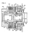
- Figure 2 is a sectional view of the driving power transmission device;
- Figure 3 is a block diagram showing the schematic construction of the control device;
- Figure 4 is a flowchart showing a switching control program executed by the control device;
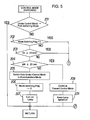
- Figure 5 is a flowchart showing another control program executed by the control device;
- Figure 6 is a partial flowchart constituting a part of the control program shown in Figure 5; and
- Figures 7(a), 7(b) and 7(c) are graphs respectively showing an example of the relation between the vehicle speed and the transmitted torque value, an example of the relation between the transmitted torque value and the lapsed time before and after the switching of the drive mode and an example of the transient state of mode indication lamps in connection with lapsed time before and after the switching of the drive mode.
-
- The present invention relates to a control device for electrically controlling a driving
power transmission device 20 installed on a front-and-rearwheel drive vehicle 10. Figure 1 schematically shows the front-and-rearwheel drive vehicle 10. Figure 2 shows the drivingpower transmission device 20. Figure 3 shows acontrol device 30 for controlling the drivingpower transmission device 20. - The front-and-rear
wheel drive vehicle 10 is of the type having front wheels 15 as primary driven wheels and rear wheels 19 as secondary driven wheels. The vehicle has a driving power transmission path for transmitting the driving power from an engine 11 to rear wheels 19. The drivingpower transmission device 20 is arranged on the driving power transmission path. - In the front-and-rear
wheel drive vehicle 10, the driving power generated in the engine 11 is transmitted to axle shafts 14 at the front wheel side through atransmission 12 and a center differential 13 for driving the front wheels 15 and is also transmitted to afirst propeller shaft 16a which constitutes the driving power transmission path. - In this configuration, when the driving
power transmission device 20 is being driven by thecontrol device 30 to keep thefirst propeller shaft 16a in driving connection to a second propeller shaft 16b, the driving power of thefirst propeller shaft 16a is transmitted to the second propeller shaft 16b. The driving force transmitted to the second propeller shaft 16b is transmitted to rear wheel axle shafts 18 through a rear differential 17 to drive the rear wheels 19. - The driving
power transmission device 20 is a known driving power transmission device incorporating an electromagnetic pilot drive mechanism therein. As shown in Figure 2, the drivingpower transmission device 20 is composed of anouter case 20a as outer rotational member, aninner shaft 20b as inner rotational member, amain clutch mechanism 20c, acam mechanism 20d and apilot clutch mechanism 20e. - The
outer case 20a constituting the drivingpower transmission device 20 comprises afront housing 21a with a bottom wall portion at one end and an opening portion at the other end and arear housing 21b fluid-tightly closing the other end opening portion of thefront housing 21a. Therear housing 21b is securely screwed into the other end opening portion of thefront housing 21a to cover the other end opening portion. - The
front housing 21a is made of a non-magnetic material (e.g., stainless steel), and thefirst propeller shaft 16a is connected to the front face of the bottom wall of thefront housing 21a for torque transmission. Therear housing 21b is composed of inner and outer cylindrical portions 21b1 and 21b2 made of a magnetic material (e.g., iron) and an intermediate cylindrical portion 21b3 made of a non-magnetic material (e.g., stainless steel) fixed by welding, for example, between the both cylindrical portions 21b1 and 21b2. - The
inner shaft 20b is coaxially inserted into thefront housing 21a and fluid-tightly pierces through the central portion of therear housing 21b. Theinner shaft 20b is rotatably supported by thefront housing 21a and therear housing 21b with the axial movement thereof inhibited. Themain clutch mechanism 20c, thecam mechanism 20d and thepilot clutch mechanism 20e are arranged between the outer surface of theinner shaft 20b and the internal surface of theouter case 20a. One end portion of the second propeller shaft 16b is inserted into the rear end portion of theinner shaft 20b to be drivingly connected to theinner shaft 20b. - The main
clutch mechanism 20c is a wet-type, multiple-plate friction clutch having a plurality of clutch plates (innerclutch plates 22a and outer clutch plates 22b) and is arranged close to the bottom wall portion between the internal surface of thefront housing 21a and the outer surface of theinner shaft 20b in thefront housing 21a. Each innerclutch plate 22a constituting the friction clutch is spline-engaged with an outer spline on the outer surface of theinner shaft 20b to be axially slidable relative to the same. In addition, each outer clutch plate 22b is spline-engaged with an inner spline on the internal surface of thefront housing 21a to be axially slidable relative to the same. Each of the innerclutch plates 22a and each of the outer clutch plates 22b are arranged in an alternate fashion and are brought into friction engagement when coming into contact with each other or out of friction engagement when going away from each other. - The
cam mechanism 20d is arranged close to the other end of the mainclutch mechanism 20c between the internal surface of thefront housing 21a and the outer surface of theinner shaft 20b. Thecam mechanism 20d is composed of afirst cam member 23, asecond cam member 24 and a plurality ofcam followers 25. Thefirst cam member 23 is spline-engaged with the outer spline on the outer surface of theinner shaft 20b to be axially movable relative to the same and is held to closely face one at the other end of the innerclutch plates 22a constituting the mainclutch mechanism 20c. Thesecond cam member 24 is smaller in diameter than thefirst cam member 23 and has an outer spline on the outer surface thereof. Thesecond cam member 24 is supported on the outer surface of theinner shaft 20b rotatably relative to the same. Each of thecam followers 25 takes a ball-like shape and is held engaged with mating ball grooves formed on the confrontation surfaces of thecam members - The pilot
clutch mechanism 20e is an electromagnetic friction clutch composed of anelectromagnet 26a, ayoke 26b, anarmature 26c and afriction clutch 27. Theelectromagnet 26a takes a ring shape and is received in an annularhollow portion 21 c of the rear housing 21 with itself being secured to theyoke 26b. Theyoke 26b is supported on therear housing 21b with a small clearance relative thereto to be rotatable relative to therear housing 21b. In the pilotclutch mechanism 20e of the construction mentioned above, therear housing 21b functions as a supporting member for supporting theyoke 26b with theelectromagnet 26a fixed thereon and also functions as a magnetic path forming member. - The
friction clutch 27 is a wet-type, multiple-plate friction clutch composed of several innerclutch plates 27a and several outer clutch plates 27b. The innerclutch plates 27a are spline-engaged with an outer spline on the outer surface of thesecond cam member 24 constituting thecam mechanism 20d and are axially movable relative to thesecond cam member 24. Each of the outer clutch plates 27b is spline-engaged with the inner spline on the internal surface of thefront housing 21a and is axially movable relative to thefront housing 21a. Thearmature 26c takes a ring shape and is spline-engaged with the inner spline on the internal surface of thefront housing 21a to be axially movable relative to thefront housing 21 a. Thearmature 26c is positioned at the front side of the friction clutch 27 closely thereto. - In the driving
power transmission device 20 as constructed above, the magnetic path is not formed and thefriction clutch 27 is not engaged while an electric current is not applied to an electromagnetic coil of theelectromagnet 26a constituting the pilotclutch mechanism 20e. In this state, the pilotclutch mechanism 20e is not active, and in thecam mechanism 20d. thesecond cam member 24 is rotatable bodily with thefirst cam member 23 through thecam follower 25 to keep the mainclutch mechanism 20c out of engagement. Thus, thevehicle 10 is put in the two-wheel drive mode. - On the other hand, when an electric current is supplied to the electromagnetic coil of the
electromagnet 26a, a magnetic path having a starting point at theelectromagnet 26a and circulating through theyoke 26b, therear cover 21b, thefriction clutch 27 and thearmature 26c is formed in the pilotclutch mechanism 20e, and theelectromagnet 26a attracts thearmature 26c. Thus, thearmature 26c is pressured on the friction clutch 27 to bring the same into friction engagement. As a result, pilot torque is generated in the pilotclutch mechanism 20e, and relative rotation takes place between thefirst cam member 23 and thesecond cam member 24 thereby to pressure thefirst cam member 23 on the mainclutch mechanism 20c by the action of thecam followers 25 against the ball grooves. - Consequently, the main
clutch mechanism 20c is frictionally engaged in proportion to the friction force exerted on thefriction clutch 27, and the torque depending on such friction is transmitted between theouter case 20a and theinner shaft 20b. Thus, thevehicle 10 is placed in the four-wheel drive mode wherein thefirst propeller shaft 16a and the second propeller shaft 16b are in an intermediate state between an uncoupled state and a directly coupled state. - In the four-wheel-drive mode, the
control device 30 automatically controls the driving power distribution ratio within the range of 100 : 0 (two-wheel drive state) to 50 : 50 (direct coupling state). In the four-wheel-drive vehicle 10, the four-wheel drive mode is referred to as automatic mode in the four-wheel drive (i.e., automatic four-wheel drive mode). - Further, when the electric current to the
electromagnet 26a is increased to a predetermined level, the attraction force of theelectromagnet 26a to thearmature 26c is increased, and thearmature 26c is strongly attracted to gain the friction-engagement force of thefriction clutch 27. This results in greater relative movement between thefirst cam member 23 and thesecond cam member 24. - Therefore, the pressuring force of the
first cam member 23 on the mainclutch mechanism 20c is further strengthened to bring the mainclutch mechanism 20c into the directly coupled state. Thus, the vehicle is placed in the four-wheel drive mode wherein thefirst propeller shaft 16a and the second propeller shaft 16b are directly coupled. In the front-and-rearwheel drive vehicle 10, the four-wheel drive mode in this state is referred to as lock mode in the four-wheel drive (i.e., four-wheel drive lock mode) and also referred to otherwise as sports four-wheel drive mode. - The front-and-rear
wheel drive vehicle 10 is constructed so that the driver can arbitrarily select either of the two-wheel drive mode, the automatic four-wheel drive mode and the four-wheel drive lock mode. In the front-and-rearwheel drive vehicle 10, aselection switch 34 is arranged beside the driver's seat, and the switching by the driver of theselection switch 34 enables a switching command signal to be output to thecontrol device 30. In dependence on the switching command signal, thecontrol device 30 controls the electric current to the electromagnetic coil of the pilotclutch mechanism 20e constituting the drivingpower transmission device 20, whereby the drive mode of thevehicle 10 is switched to a selected one of the drive modes. - It is to be noted that when the drive mode of the
vehicle 10 is switched to the automatic four-wheel-drive mode, thecontrol device 30 automatically controls thevehicle 10 to place the same in a four-wheel drive state suitable to the present driving status based on the detected signals from a throttle sensor 31, front-wheel speed sensors 32, rear-wheel speed sensors 33 and so on which are arranged on thevehicle 10, as shown in Figure 1. - Referring now to Figure 3, the
control device 30 is provided including an MPU (microprocessor) and a drive circuit. The MPU incorporates a CPU and a memory (both not shown) therein, and the memory has stored therein control programs and various data for controlling the operation of the drivingpower transmission device 20. Thecontrol device 30 takes thereinto the detection signals from the throttle sensor 31, the front-wheel speed sensors 32, the rear-wheel speed sensors 33 and the like as well as the switching command signal from theselection switch 34 operated by the driver, through an interface (not shown). - Based on the switching command signal taken thereinto, the MPU outputs a command signal for instructing the
vehicle 10 to be placed in a drive mode as commanded, to a drive circuit (not numbered) through the interface. In response to the output command signal, the drive circuit controls the electric current to the electromagnetic coil of the pilotclutch mechanism 20e thereby to switch the drive mode of thevehicle 10 to the selected drive mode. Furthermore, based on the various detection signals take thereinto, the MPU outputs a command signal for automatically controlling the four-wheel drive status of thevehicle 10, to the drive circuit through the interface. In response to the output command signal, the drive circuit also controls the electric current to the electromagnetic coil of the pilotclutch mechanism 20e thereby to place thevehicle 10 in the four-wheel drive state suitable to the present driving status. - The
control device 30 has stored therein a switching control program for selectively switching the drive mode of thevehicle 10 to the two-wheel drive mode, the automatic four-wheel drive mode or the four-wheel drive lock mode. This switching control constitutes the important part of the present invention, wherein the first switching control is a control function for inhibiting the switching operation to any commanded drive mode, the second switching control is a control function for gradually switching the switching operation to any such commanded drive mode, and the third switching control is a control function for performing both of these control functions. - In the first switching control, the
control device 30 inhibits the switching to any commanded four-wheel drive mode while thevehicle 10 traveling at a low speed in the two-wheel drive mode is suffering a large slip. In this case, thecontrol device 30 executes the switching to any such commanded four-wheel drive mode after thevehicle 10 traveling at the low speed in the two-wheel drive mode comes out of the state under such a large slip. This prevents the torque exceeding a predetermined value and abnormal sounds or noises from being generated in the drive system - Furthermore, the
control device 30 in the second switching control restrains the torque of thevehicle 10 at the time of such switching from being suddenly transmitted to the secondary driven wheels 19 so that the driving power during the traveling of thevehicle 10 can be prevented from being abruptly changed due to the instantaneous switching of the drive mode. Thus, it becomes possible to prevent the motion of thevehicle 10 during a turn from being changed abruptly. In addition, thecontrol device 30 in the third switching control performs a control combining the first switching control and the second switching control. - The
control device 30 in this particular embodiment serves as afirst control device 30a storing a control program for the aforementioned first switching control, asecond control device 30b storing another control program for the aforementioned second switching control and athird control device 30c storing another control program for the aforementioned third switching program which incorporates the first and second switching controls. - The four-
wheel drive vehicle 10 is further provided with several indication lamps which serve as drive mode lamps for indicating respective present drive modes assigned thereto, wherein the aforementioned first tothird control devices 30a through 30c have the functions for turning on the indication lamps which correspond to selected drive modes, respectively. In addition, each of thecontrol devices 30a through 30c also has a function for winking or blinking one of the indication lamps corresponding to a commanded drive mode. Each indication lamp when blinking indicates that the drive mode which is commanded to be switched to is in curse of being switched to. - Figure 4 shows a flowchart for enabling the aforementioned
second control device 30b to execute the control program stored therein, while Figures 5 and 6 show another flow chart for enabling the aforementionedthird control device 30c to execute the control program stored therein. When the driver issues a switching command to one of the drive modes by switching theselection switch 34, thecontrol device - The switching control is performed by controlling the electric current to the electromagnetic coil of the drive
power transmission device 20 so that the friction engagement force (i.e., transmission torque value) of the mainclutch mechanism 20c of the drivingpower transmission device 20 is controlled to the transmission torque value corresponding to a selected drive mode. Figure 7 (a) is a graph showing an example of the relation between the vehicle speed and the torque value in each of the drive modes. Figure 7 (b) is a graph showing the relation between the transmission torque value and the lapsed time in transition of the switching between the drive modes. Figure 7 (c) is a graph showing an example of the state that the indication lamps are switched in transition of the switching between the drive modes. - In the front-and rear
wheel drive vehicle 10 incorporating thecontrol device 30b therein, when the drive mode is switched from one to another by the driver's switching manipulation of theselection switch 34, thecontrol device 30b executes the drive mode switching control program in accordance with the flowchart illustrated in Figure 4 to control the drive mode switching. - The microcomputer constituting the
control device 30b judges atstep 101 whether or not the drive mode presently under control (under-control mode) is the same as the drive mode selected to be switched to by the selection switch 34 (post-switching mode or switch-selected mode). When the microcomputer judges that the under-control mode and the switch-selected mode are identical, the microcomputer goes back to the starting point of the switching control program without executing the subsequent steps of the switching control program. On the contrary, when the microcomputer judges that the under-control mode and the switch-selected mode are not identical, the microcomputer advances its routine to step 102. The microcomputer sets a mode switching flag to "1" atstep 102 and further advances the program routine to step 103. - At step103, the microcomputer judges the difference between the present transmission torque value (present torque) of the driving
power transmission device 20 and a transmission torque value (target or post-switching torque) to be set based on, e.g., the graph shown in Figure 7 (a) in another drive mode which is now selected to be switched to. When the difference between the present torque and the target or post-switching torque is judged to be larger than a predetermined value (e.g., 20Nm), the microcomputer advances the program routine in turn to step 104 andstep 105. - At
step 104, the microcomputer gradually changes the transmission torque value of the drivingpower transmission device 20 from the present torque to the post-switching torque along an inclination determined by a predetermined time constant (τ) (e.g., 0.7s (= 0.7 seconds): the valve determining the inclination along which the torque is varied from a present value to a target value). Under this control (gradual switching control), the transmission torque value is not varied quickly or instantaneously as is done in the prior art as indicated by the dotted line in Figure 7 (b) but is varied gradually as indicated by the inclined solid line in Figure 7 (b). - At
step 105, the microcomputer winks or blinks the indication lamp identifying the selected drive mode during the gradual switching control (during the course of switching) as shown, for example, in Figure 7 (c). Then, the microcomputer returns the processing routine to the starting point. - Further, when judging at
step 103 that the difference between the present torque and the target or post-switching torque is equal to or smaller than the predetermined value (e.g., 20 Nm), the microcomputer moves the processing routine to step 106, so that the gradual switching control atstep 104 is skipped to complete the switching to the post-switching mode instantaneously. Thereafter, the microcomputer clears the mode switching flag (i.e., sets the flag to "0") atstep 107 and turns on the indication lamp for the selected drive mode atstep 108. - As described above, according to the switching control of the drive mode by the
control device 30b, the control function for gradually executing the switching to the selected drive mode restrains the torque generated in thevehicle 10 at the time of the switching commanded, from being transmitted instantaneously to the driven wheels 19, whereby the driving power of the vehicle traveling is prevented from being abruptly changed due to the instantaneous change of the drive mode. Accordingly, it can be realized to obviate the sudden change in the motion of the vehicle in the course of the vehicle making a turn. - In the front-and-
rear drive vehicle 10 with thecontrol device 30c, when the driver's switching manipulation of theselection switch 34 causes the drive mode to be switched, thecontrol device 30c executes the drive mode switching control program in accordance with the flowcharts shown in Figures 5 and 6 and controls the switching to the selected drive mode. - At
step 201, the microcomputer constituting thecontrol device 30c judges whether or not the drive mode presently under control (under-control mode) is the same as the selected mode (post-switching mode) which is commanded to be switched to by theselection switch 34. When judging that the under-control mode is the same as the post-switching mode, the microcomputer returns the program routine to the starting point without executing those steps followed. - Further, when judging at
step 201 that the under-control mode is not the same as the post-switching mode, the microcomputer further proceeds to step 202 in the switching control program and judges the status of the mode switching flag. When judging atstep 202 that the mode switching flag has not been set to "1", the microcomputer moves the processing routine to step 203 throughstep 209. If the flag is found to have been set to "1" atstep 202, on the other hand, the microcomputer proceeds to step 210 throughstep 216 shown in Figure 6.Steps 210 through 216 correspond to the gradual switching control and the instantaneous mode switching control executed in accordance with the switch control program (i.e., steps 103 through 108) shown in Figure 4. Therefore, a gradual mode switching control atstep 212 or an instantaneous mode switching control atstep 214 is performed in dependence on the result of judgment atstep 211 in the same way as that executed atstep 104 or step 106 in Figure 4. - At
step 203, the microcomputer compares the vehicle speed with the predetermined value (e.g., 20 km/h). When the vehicle speed is found to be equal to or higher than the predetermined value, the microcomputer advances the program routing to step 210 to execute the aforementioned switching control program. On the other hand, when the vehicle speed is found to be slower than the predetermined value, the microcomputer advances the program routine to step 204. - At
step 204, the microcomputer compares the rotational difference (ΔN) between the front and rear wheels 15, 19 with a predetermined value (e.g., 20 rpm). When the rotational difference (ΔN) is found to be equal to or larger than the predetermined value, the microcomputer proceeds to step 208 andstep 209. The microcomputer continues the under-control mode atstep 208 and keeps the lamp, identifying the under-control drive mode, turned on atstep 209. When thevehicle 10 is in this drive state with the large rotational speed difference (ΔN), the microcomputer returns the program routine to the starting point, so that the execution of the switching control can be delayed until thevehicle 10 comes out from the state of the large rotational speed difference (ΔN), as referred to the next. Thus, thestep 208 serves to inhibit the drive mode of thevehicle 10 from being switched to the commanded drive mode instantaneously. - That is, when judging at
step 204 that the rotational difference (ΔN) is less than the predetermined value (e.g., 20 rpm), the microcomputer proceeds to step 205 throughstep 207. The microcomputer completes the switching from the under-control mode to the post-switching mode quickly or instantaneously atstep 205, clears the mode switching flag atstep 206 and turns on the indication lamp corresponding to the selected drive mode atstep 207. - As described above, according to the switching control of the drive mode by the
control device 30c, the control function for disabling the transition to a commanded drive mode disables the instantaneous transition to the commanded four-wheel drive mode when the vehicle traveling at a low speed in the two-wheel drive mode is making a large slip, for example. Then, thecontrol device 30c puts thevehicle 10 in the four-wheel drive mode after the vehicle traveling at the low speed in the two-wheel drive mode comes out from the above large slip status. This construction prevents the torque from being generated beyond a tolerable or allowable maximum value and abnormal sounds or noises from be made from the driving power transmission path. - As described above, according to the switching control of the drive mode by the
control device 30b, the control function for gradually making the transition to the commanded drive mode prevents the torque generated in thevehicle 10 from being transmitted instantaneously thereby to avoid the sudden change in the driving power caused by the instantaneous change of the drive mode during the traveling of the vehicle. Thus, in addition to the foregoing functions and advantages, it can also be realized to prevent the vehicle from suddenly changing the motion thereof while making a turn, for example. - Obviously, numerous modifications and variations of the present invention are possible in light of the above teachings. It is therefore to be understood that within the scope of the appended claims, the present invention may be practiced otherwise than as specifically described herein.
- A control device is provided for electrically controlling a drive power transmission device arranged on a driving power transmission path of a front-and rear wheel drive vehicle thereby to switch the drive mode of the vehicle selectively to either of a two-wheel drive mode and a four-wheel drive mode. The control device inhibits the drive mode from being switched to that commanded to be switched to when the vehicle is traveling at a slower speed than a predetermined speed and when the rotational speed difference between front and rear wheels is larger than a predetermined value. Further, the control device gradually decreases a present torque which the driving power transmission device is transmitting before the switching of the drive mode, to a target torque which the drive power transmission device is to transmit after the switching of the drive mode, when the difference between the present and target torques is more than another predetermined valve at the time of the switching of the drive mode. Thus, the driving power transmission path can be prevented from generating the drive torque beyond a tolerable valve as well as making a noise due to the instantaneous switching of the drive mode during the traveling of the vehicle, and the vehicle can be prevented from abruptly changing its motion by the cause of the instantaneous drive mode switching.
Claims (8)
- A control device for a front-and-rear wheel drive vehicle for electrically controlling a driving power transmission device which is arranged on a driving power transmission path of said vehicle for transmitting the drive power from a power source to driven wheels as either of front wheels and rear wheels of said vehicle, said control device including:switching control means for electrically controlling said driving power transmission device to switch the drive mode of said vehicle selectively to a two-wheel drive mode or a four-wheel drive mode; andswitching inhibiting means for inhibiting the drive mode of said vehicle from being switched to a commanded one of said drive modes when said vehicle is traveling at a lower speed than a predetermined value and when the rotational speed difference between front and rear wheels is larger than a predetermined difference.
- A control device for a front-and-rear wheel drive vehicle for electrically controlling a driving power transmission device which is arranged on a driving power transmission path of said vehicle for transmitting the drive power from a power source to driven wheels as either of front wheels and rear wheels of said vehicle, said control device including:switching control means for electrically controlling said driving power transmission device to switch the drive mode of said vehicle selectively to a two-wheel drive mode or a four-wheel drive mode: andgradual switching control means for electrically controlling said driving power transmission device to gradually decrease a present torque which said driving power transmission device is transmitting before the switching of said drive mode, to a target torque which said drive power transmission device is to transmit after the switching of said drive mode, when the difference between said present and target torques is more than a predetermined valve at the time of the switching of said drive mode.
- The control device for a front-and-rear wheel drive vehicle as set forth in Claim 2, wherein said gradual switching control means gradually decreases said present torque to said target torque when the difference between said present and target torques is more than said predetermined valve at the time of the switching of said drive mode and when the traveling speed of said vehicle is equal to or more than a predetermined medium speed.
- A control device for a front-and-rear drive wheel vehicle for electrically controlling a driving power transmission device which is arranged on a driving power transmission path of said vehicle for transmitting the drive power from a power source to driven wheels as either of front wheels and rear wheels of said vehicle, said control device including:switching control means for electrically controlling said driving power transmission device to switch the drive mode of said vehicle selectively to a two-wheel drive mode or a four-wheel drive mode;switching inhibiting means for inhibiting the drive mode of said vehicle from being switched to a commanded one of said drive modes when said vehicle is traveling at a lower speed than a predetermined value and when the rotational speed difference between front and rear wheels is larger than a predetermined difference; andgradual switching control means for electrically controlling said driving power transmission device to gradually decrease a present torque which said driving power transmission device is transmitting before the switching of said drive mode, to a target torque which said drive power transmission device is to transmit after the switching of said drive mode, when the difference between said present and target torques is more than a predetermined valve at the time of the switching of said drive mode.
- The control device for a front-and-rear wheel drive vehicle as set forth in Claim 4, wherein said gradual switching control means gradually decreases said present torque to said target torque when the difference between said present and target torques is more than said predetermined valve at the time of the switching of said drive mode and when the traveling speed of said vehicle is equal to or more than a predetermined medium speed.
- The control device for a front-and-rear wheel drive vehicle as set forth in Claim 1, further including:lamp control means for selectively turning on or off a drive mode lamp which is provided on the vehicle to indicate the drive mode of said vehicle being presently selected.
- The control device for a front-and-rear wheel drive vehicle as set forth in Claim 2, further including:lamp control means for selectively turning on or off a drive mode lamp which is provided on the vehicle to indicate the drive move of said vehicle being presently selected, said lamp control means being operable to blink said drive mode lamp while said gradual switching control means gradually decreases said present torque to said target torque.
- The control device for a front-and-rear wheel drive vehicle as set forth in Claim 4, further including:lamp control means for selectively turning on or off a drive mode lamp which is provided on the vehicle to indicate the drive move of said vehicle being presently selected, said lamp control means being operable to blink said drive mode lamp while said gradual switching control means gradually decreases said present torque to said target torque.
Applications Claiming Priority (2)
| Application Number | Priority Date | Filing Date | Title |
|---|---|---|---|
| JP2003123080A JP4449330B2 (en) | 2003-04-28 | 2003-04-28 | Control device for front and rear wheel drive vehicles |
| JP2003123080 | 2003-04-28 |
Publications (3)
| Publication Number | Publication Date |
|---|---|
| EP1473184A2 true EP1473184A2 (en) | 2004-11-03 |
| EP1473184A3 EP1473184A3 (en) | 2005-11-09 |
| EP1473184B1 EP1473184B1 (en) | 2008-11-26 |
Family
ID=32985545
Family Applications (1)
| Application Number | Title | Priority Date | Filing Date |
|---|---|---|---|
| EP04009969A Expired - Fee Related EP1473184B1 (en) | 2003-04-28 | 2004-04-27 | Control device for front-and-rear wheel drive vehicle |
Country Status (4)
| Country | Link |
|---|---|
| US (1) | US7490690B2 (en) |
| EP (1) | EP1473184B1 (en) |
| JP (1) | JP4449330B2 (en) |
| DE (1) | DE602004017929D1 (en) |
Families Citing this family (12)
| Publication number | Priority date | Publication date | Assignee | Title |
|---|---|---|---|---|
| US7357749B2 (en) * | 2005-12-15 | 2008-04-15 | Eaton Corporation | Limited slip differential and engagement sensing mechanism therefor |
| JP5246676B2 (en) * | 2006-12-27 | 2013-07-24 | 本田技研工業株式会社 | Shift map switching control device |
| EP2353918A1 (en) * | 2010-01-13 | 2011-08-10 | Jtekt Corporation | Driving force transmission apparatus and control method therefor |
| JP5523869B2 (en) * | 2010-02-26 | 2014-06-18 | アイシン・エーアイ株式会社 | Vehicle driving state control device |
| US10166865B2 (en) * | 2010-10-18 | 2019-01-01 | Ford Global Technologies, Llc | Automatic control of driveline states |
| GB2488529A (en) * | 2011-02-18 | 2012-09-05 | Land Rover Uk Ltd | Vehicle with power transfer clutch actuator which reduces mode chattering |
| JP5849770B2 (en) * | 2012-02-29 | 2016-02-03 | 株式会社ジェイテクト | Four-wheel drive vehicle and control device for four-wheel drive vehicle |
| US9566861B2 (en) * | 2012-06-22 | 2017-02-14 | Toyota Jidosha Kabushiki Kaisha | Vehicle control device |
| WO2015129694A1 (en) | 2014-02-27 | 2015-09-03 | 日産自動車株式会社 | Clutch control device for 4-wheel drive vehicle |
| JP6476982B2 (en) | 2015-02-20 | 2019-03-06 | 三菱自動車工業株式会社 | Four-wheel drive vehicle control system |
| US9950618B2 (en) * | 2015-02-20 | 2018-04-24 | Mitsubishi Jidosha Kogyo Kabushiki Kaisha | Controller of four-wheel drive vehicle |
| JP2020048296A (en) * | 2018-09-18 | 2020-03-26 | 本田技研工業株式会社 | Control system of four-wheel drive vehicle and control method of four-wheel drive vehicle |
Citations (1)
| Publication number | Priority date | Publication date | Assignee | Title |
|---|---|---|---|---|
| JP2001082571A (en) | 1999-09-16 | 2001-03-27 | Toyoda Mach Works Ltd | Action force conversion mechanism and driving force transmission device using the same |
Family Cites Families (8)
| Publication number | Priority date | Publication date | Assignee | Title |
|---|---|---|---|---|
| DE3543894A1 (en) * | 1985-12-12 | 1987-06-19 | Wabco Westinghouse Fahrzeug | OPERATING DEVICE FOR A DIFFERENTIAL LOCK |
| CA1322239C (en) | 1987-01-23 | 1993-09-14 | James J. Coogan | System for controlling torque transmission in a four wheel drive vehicle |
| KR0134200B1 (en) * | 1994-09-21 | 1998-04-18 | 쭈지 요시후미 | Four wheel driving e system |
| US5819194A (en) * | 1994-09-21 | 1998-10-06 | Nissan Motor Co., Ltd. | System for controlling four-wheel drive for motor vehicle |
| US6481304B1 (en) * | 1999-02-05 | 2002-11-19 | Mitsubishi Jidosha Kogyo Kabushiki Kaisha | Driving-state switching device equipped with synchronizing mechanism |
| JP3520915B2 (en) | 2000-09-19 | 2004-04-19 | 日産自動車株式会社 | Front and rear wheel torque distribution control device for four-wheel drive vehicle |
| US6450921B1 (en) * | 2000-10-11 | 2002-09-17 | Ford Global Technologies, Inc. | System and method for controlling a transfer case clutch assembly |
| US6645108B1 (en) * | 2002-05-16 | 2003-11-11 | The Timken Company | Active torque bias system and controls |
-
2003
- 2003-04-28 JP JP2003123080A patent/JP4449330B2/en not_active Expired - Lifetime
-
2004
- 2004-04-21 US US10/828,277 patent/US7490690B2/en active Active
- 2004-04-27 EP EP04009969A patent/EP1473184B1/en not_active Expired - Fee Related
- 2004-04-27 DE DE602004017929T patent/DE602004017929D1/en not_active Expired - Lifetime
Patent Citations (1)
| Publication number | Priority date | Publication date | Assignee | Title |
|---|---|---|---|---|
| JP2001082571A (en) | 1999-09-16 | 2001-03-27 | Toyoda Mach Works Ltd | Action force conversion mechanism and driving force transmission device using the same |
Also Published As
| Publication number | Publication date |
|---|---|
| EP1473184A3 (en) | 2005-11-09 |
| JP4449330B2 (en) | 2010-04-14 |
| DE602004017929D1 (en) | 2009-01-08 |
| JP2004322940A (en) | 2004-11-18 |
| US7490690B2 (en) | 2009-02-17 |
| EP1473184B1 (en) | 2008-11-26 |
| US20040211611A1 (en) | 2004-10-28 |
Similar Documents
| Publication | Publication Date | Title |
|---|---|---|
| US7490690B2 (en) | Control device for front-and-rear wheel drive vehicle | |
| EP1223361B1 (en) | Power transfer device | |
| US7270205B2 (en) | Vehicle drive device, and front-and-rear wheel-driven vehicle formed of the device | |
| JP3157244B2 (en) | Vehicle differential limiter | |
| JPH054531A (en) | Control device for vehicle | |
| EP1375231B1 (en) | Drive power distribution control method and device for four-wheel drive vehicle | |
| US6907953B2 (en) | Driving force distribution control device and driving force distribution method for four-wheel drive vehicle | |
| JP2012061923A (en) | Four-wheel-drive vehicle and control device for the same | |
| EP1308336B1 (en) | Power distribution control apparatus for four-wheel drive vehicle and a method for contolling the apparatus | |
| EP1495903B1 (en) | Power distribution control apparatus of four-wheel drive vehicle | |
| US20070295548A1 (en) | Prevention of inadvertent inertial engagement of a transfer case clutch | |
| JP2004092570A (en) | Driving force transmission/control device | |
| US6842682B2 (en) | Driving force distribution method and apparatus | |
| JPH0899642A (en) | Steering assisting device for vehicle | |
| US5056634A (en) | Control apparatus of a remote type free wheel | |
| JP3823072B2 (en) | Front and rear wheel drive vehicles | |
| US20040003953A1 (en) | Two-wheel/four-wheel drive switching device for vehicle | |
| JP2005083464A (en) | Four-wheel drive device | |
| JP4078004B2 (en) | Electromagnetic clutch and driving force transmission device using the same | |
| JP3327610B2 (en) | Vehicle differential limiter | |
| JP2004009814A (en) | Wheel driving force distribution control system | |
| JP4192955B2 (en) | Driving force transmission device | |
| JP2852516B2 (en) | Control device for continuously variable transmission | |
| EP1031749A1 (en) | An electromagnetic clutch and a driving force transmission device using the same | |
| JP2000234633A (en) | Mounting structure of electromagnet to yoke in electromagnetic clutch |
Legal Events
| Date | Code | Title | Description |
|---|---|---|---|
| PUAI | Public reference made under article 153(3) epc to a published international application that has entered the european phase |
Free format text: ORIGINAL CODE: 0009012 |
|
| AK | Designated contracting states |
Kind code of ref document: A2 Designated state(s): AT BE BG CH CY CZ DE DK EE ES FI FR GB GR HU IE IT LI LU MC NL PL PT RO SE SI SK TR |
|
| AX | Request for extension of the european patent |
Extension state: AL HR LT LV MK |
|
| PUAL | Search report despatched |
Free format text: ORIGINAL CODE: 0009013 |
|
| AK | Designated contracting states |
Kind code of ref document: A3 Designated state(s): AT BE BG CH CY CZ DE DK EE ES FI FR GB GR HU IE IT LI LU MC NL PL PT RO SE SI SK TR |
|
| AX | Request for extension of the european patent |
Extension state: AL HR LT LV MK |
|
| 17P | Request for examination filed |
Effective date: 20060130 |
|
| AKX | Designation fees paid |
Designated state(s): DE FR GB |
|
| RAP1 | Party data changed (applicant data changed or rights of an application transferred) |
Owner name: JTEKT CORPORATION |
|
| RIN1 | Information on inventor provided before grant (corrected) |
Inventor name: OHNO, AKIHIRO Inventor name: YAMADA, YASUSHI |
|
| 17Q | First examination report despatched |
Effective date: 20060403 |
|
| GRAP | Despatch of communication of intention to grant a patent |
Free format text: ORIGINAL CODE: EPIDOSNIGR1 |
|
| GRAS | Grant fee paid |
Free format text: ORIGINAL CODE: EPIDOSNIGR3 |
|
| GRAA | (expected) grant |
Free format text: ORIGINAL CODE: 0009210 |
|
| AK | Designated contracting states |
Kind code of ref document: B1 Designated state(s): DE FR GB |
|
| REG | Reference to a national code |
Ref country code: GB Ref legal event code: FG4D |
|
| REF | Corresponds to: |
Ref document number: 602004017929 Country of ref document: DE Date of ref document: 20090108 Kind code of ref document: P |
|
| PLBE | No opposition filed within time limit |
Free format text: ORIGINAL CODE: 0009261 |
|
| STAA | Information on the status of an ep patent application or granted ep patent |
Free format text: STATUS: NO OPPOSITION FILED WITHIN TIME LIMIT |
|
| 26N | No opposition filed |
Effective date: 20090827 |
|
| GBPC | Gb: european patent ceased through non-payment of renewal fee |
Effective date: 20090427 |
|
| PG25 | Lapsed in a contracting state [announced via postgrant information from national office to epo] |
Ref country code: GB Free format text: LAPSE BECAUSE OF NON-PAYMENT OF DUE FEES Effective date: 20090427 |
|
| PGFP | Annual fee paid to national office [announced via postgrant information from national office to epo] |
Ref country code: FR Payment date: 20120504 Year of fee payment: 9 |
|
| REG | Reference to a national code |
Ref country code: FR Ref legal event code: ST Effective date: 20131231 |
|
| PG25 | Lapsed in a contracting state [announced via postgrant information from national office to epo] |
Ref country code: FR Free format text: LAPSE BECAUSE OF NON-PAYMENT OF DUE FEES Effective date: 20130430 |
|
| PGFP | Annual fee paid to national office [announced via postgrant information from national office to epo] |
Ref country code: DE Payment date: 20210330 Year of fee payment: 18 |
|
| REG | Reference to a national code |
Ref country code: DE Ref legal event code: R119 Ref document number: 602004017929 Country of ref document: DE |
|
| PG25 | Lapsed in a contracting state [announced via postgrant information from national office to epo] |
Ref country code: DE Free format text: LAPSE BECAUSE OF NON-PAYMENT OF DUE FEES Effective date: 20221103 |